Herma LP Morgan Dipper User manual
LP Morgan
user manual
dipper
www.lpmorgan.com.au | www.herma.com.au


www.lpmorgan.com.au | www.herma.com.au
LP Morgan Dipper User’s Manual

Notes, Notices and Cautions
NOTE: A note indicates important information that helps you make better use of your Dipper.
NOTICE: A notice indicates either potential damage to ceiling or projector and tells you how to
avoid the problem.
CAUTION: A caution indicates a potential for property damage, personal injury or death.
Information in this document is subject to change without notice.
© 2002-2006 Herma Technologies. All rights reserved.
Reproduction in any manner whatsoever without permission of Herma Technologies is strictly forbidden.
Trademarks used in this text: Herma, the Herma Logo, Dipper, LP Morgan and LP Morgan logo are
registered trademarks of Herma Technologies.
Other trademarks and trade names may be used in this document to refer to either the entities claiming the
marks and names or their product. Herma Technologies disclaims interest in trademarks and trade names
other than its own.
January 2007 Version 2.3

Maintenance &
Troubleshooting
Troubleshooting/FAQ 25
Appendix
Accessories 26
Warranty Information 27
Important information
Precaution 6
To the owner 7
Unpacking 8
Part Names and Dimensions 10
Installation
Mechanical Installation 14
Ceiling opening 15
Ceiling Space 16
Ceiling type - Suspended ceiling 18
Ceiling type - Trussed ceiling 19
Electrical Installation 20
Wiring Diagram 21
Projector Installation 22
Cable Management 25
Table of contents

6 | installation instructions
Important
information
Precautions
ATTENTION: Please read all of these instructions before you operate your
Dipper for the first time. Save these instructions for further reference.
For your own protection and prolonged operation of your Dipper, be sure to read
the following precautions carefully before use.
On Safety
Check that the operating voltage of
your unit is identical with the voltage
of your local power supply. If voltage
adaptation is required, consult with
qualified an electrician.
Should liquid or solid objects fall into
the unit, unplug and have it checked by
qualified personnel before operating it
further.
To disconnect the cord, pull it out by the
plug. Never pull the cord itself.
The power supply should be near the
unit and easily accessible.
The unit is not disconnected from
the AC power source as long as it is
connected to the wall outlet, even if the
unit has been turned off.
Do not place your hand or other objects
near the trapdoor during operation.
The Skyhook Projector Mount must be
used for installation with the Dipper.
On Cleaning
To keep the unit looking new and clean
a dust cover is supplied. If cleaning is
necessary use a soft cloth and mild
detergent solution. Never use strong
solvents, such as thinners, benzene, or
abrasive cleaners.
Never operate the Dipper while the projector is still powered!

installation instructions | 7
Important
information
To the owner
Congratulations on purchasing an LP Morgan Dipper. This innovative
projector mounting system is a novel and secure way to mount your projector
out of sight when not in use, giving you maximum enjoyment and a truly
cinematic experience.
Please take a moment to review this manual, as it will ensure you many years
of trouble-free service from your new Dipper.

8 | installation instructions
Important
information
Unpacking the Dipper
When unpacking the Dipper, please handle all parts with care.
Do not destroy the inner box when unpacking, as it is the dustcover for
this unit!
T
h
e
F
a
c
e
P
l
a
t
e
o
n
t
h
i
s
p
r
o
j
e
c
t
o
r
m
o
u
n
t
h
a
s
b
e
e
n
t
r
e
a
t
e
d
o
n
l
y
w
i
t
h
a
w
a
t
e
r
-
b
a
s
e
d
u
n
d
e
r
c
o
a
t
f
o
r
y
o
u
r
c
o
n
v
e
n
i
e
n
c
e
.
T
h
i
s
w
i
l
l
e
n
a
b
l
e
y
o
u
t
o
p
a
i
n
t
i
t
t
o
m
a
t
c
h
y
o
u
r
c
e
i
l
i
n
g
.
installation instructions | 9
Important
information
12
7
34
56
1. Dipper Unit
2. Control Unit, Protective Enclosure
3. LP Morgan Skyhook Projector Mount System
(including mounting bolts and springs)
4. 24V Power Supply
5. Ceiling Face Plate
6. Ceiling Trim
7. Wall Switch and Architrave Mount
8. Cardboard Dustcover
9.Spring, Bolts Washers
8
9

10 | installation instructions
Important
information
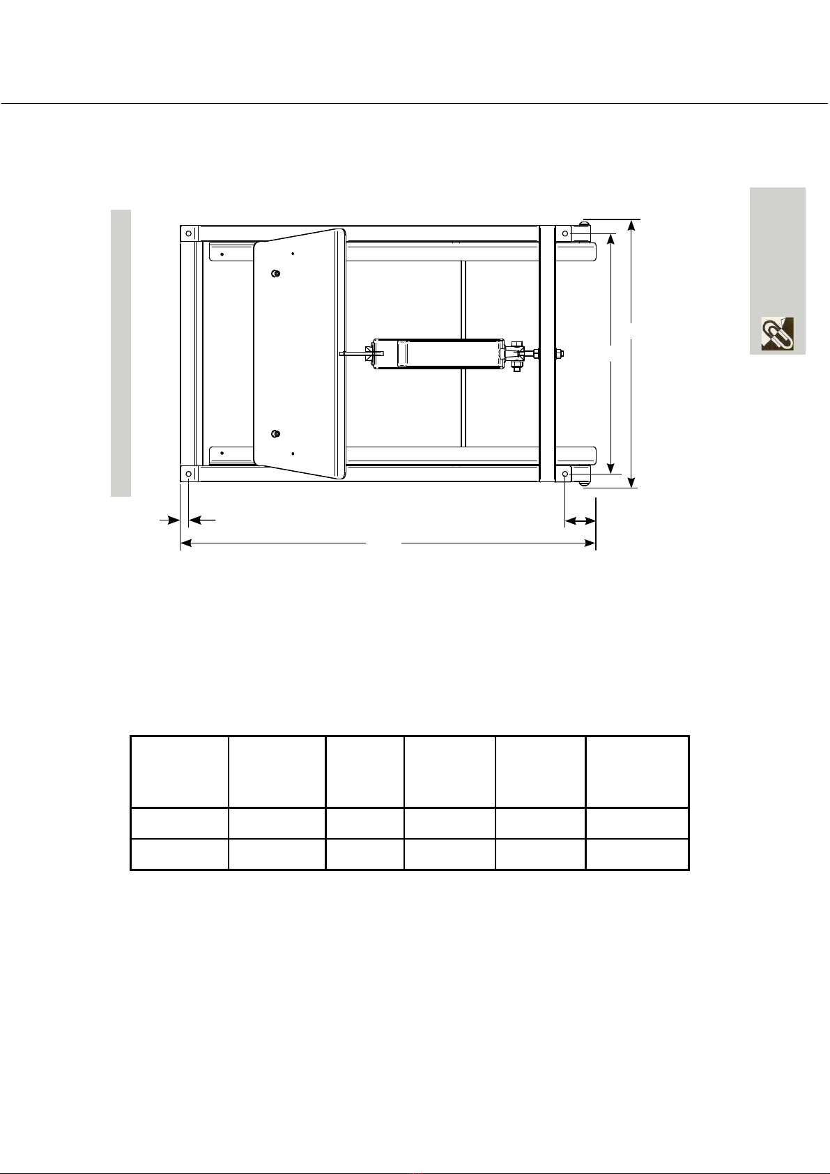
Part Names and Dimensions
Make consideration of the maintenance of the Dipper when installing it. Wherever
possible, allow access to the ceiling cavity other than through the Dipper’s hole
- so that you can access the projector if the power supply fails!
Side View
A3
B2
B1
B2
Dipper
Size
Front
Mount Tabs
(A1)
Rear
Mount Tabs
(A2)
Overall
Height
(A3)
Face Plate
to Front
(B1)
Face Plate
Length
(B2)
Face Plate
to back
(B3)
Medium 125 205 355 35 400 215
Large 125 175 430 30 500 300
A2
A1
installation instructions | 11
Important
information
Top View, Closed Position
Screen
C2
D1
D2
C1 C3
Dipper
Size
Front
mounting
hole (C1)
Overall
Length
(C2)
Rear
mounting
hole (C3)
Overall
Width
(D1)
Mounting
hole Width
(D2)
Medium 15 6500 50 405 380
Large 15 830 40 505 480

12 | installation instructions
Important
information
Front View, closed position
D3
D1
Dipper
Size
Overall
Width (D1)
Face Panel
Width (D3)
Medium 405 400
Large 505 500

installation instructions | 13
Important
information
FRONT
Front 3D View
1. Motor
2. Pivot Frame
3. Main Frame
4. Skyhook Plate
5. Mounting Tabs
6. Face Panel
1
23
4
5
6

14 | installation instructions
Mechanical
Installation
Mechanical Installation
The first crucial step, like any projector installation, is to determine where to put
the Dipper in the ceiling. The Dipper should be installed so that the projector
lens is centered horizontally to the screen, and the distance from the screen
depends on the projector’s throw distance.
Work out the maximum and minimum throw distances for the projector and
place the Dipper somewhere in between. It is better for the projector to be
closer to the screen, but don’t place it at an extreme—leave yourself some
room to adjust the zoom in either direction.
Screen
Screen center
Lens center
Projector center
Note: when aligning the Dipper
make sure that the projector
lens is centered on the screen,
which is not necessarily the
projector center.
Throw Distance
installation instructions | 15
Mechanical
Installation
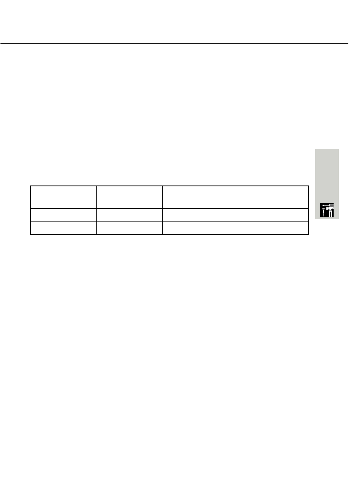
The Dipper comes with a 12mm undercoated MDF face panel and an aluminium
ceiling trim.
We recommend that you paint this panel before fixing the Dipper in the ceiling.
In the case of a non-plasterboard ceiling, you may choose to fabricate your own
ceiling panel (eg from the same timber/material as the ceiling itself) to match.
We recommend you leave a 2mm gap around all edges of the Dipper’s face
panel.
Supplied is a plastic trim that you may use to finish off the edge of the hole. The
cutout dimensions given below assume that you will use this ceiling trim.
Face Panel
L x W mm
Cutout required with ceiling trim
L X W mm
Medium Dipper 400 x 400 410 x 410
Large Dipper 500 x 500 510 x 510
Ceiling Opening
16 | installation instructions
Mechanical
Installation
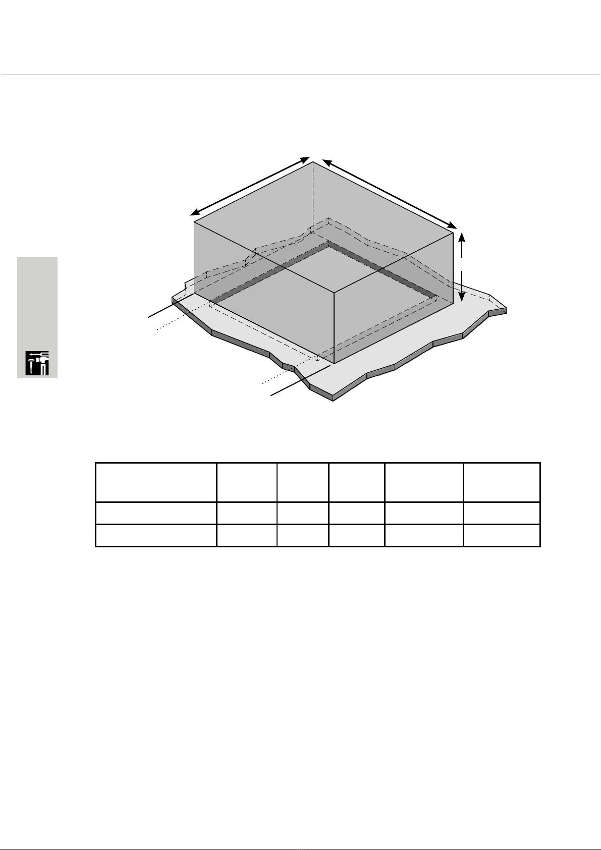
The following diagrams show the position of the ceiling cutout in relation to the
Dipper frame, and the space required above the ceiling.
Ceiling Space - Standard Dipper
Size Length
(L)
Width
(W)
Height
(H)
Front Gap
L1
Rear Gap
L2
Medium Dipper 650 405 355 32 212
Large Dipper 830 505 430 27 297
L
W
L1
L2
FRONT
H
installation instructions | 17
Mechanical
Installation
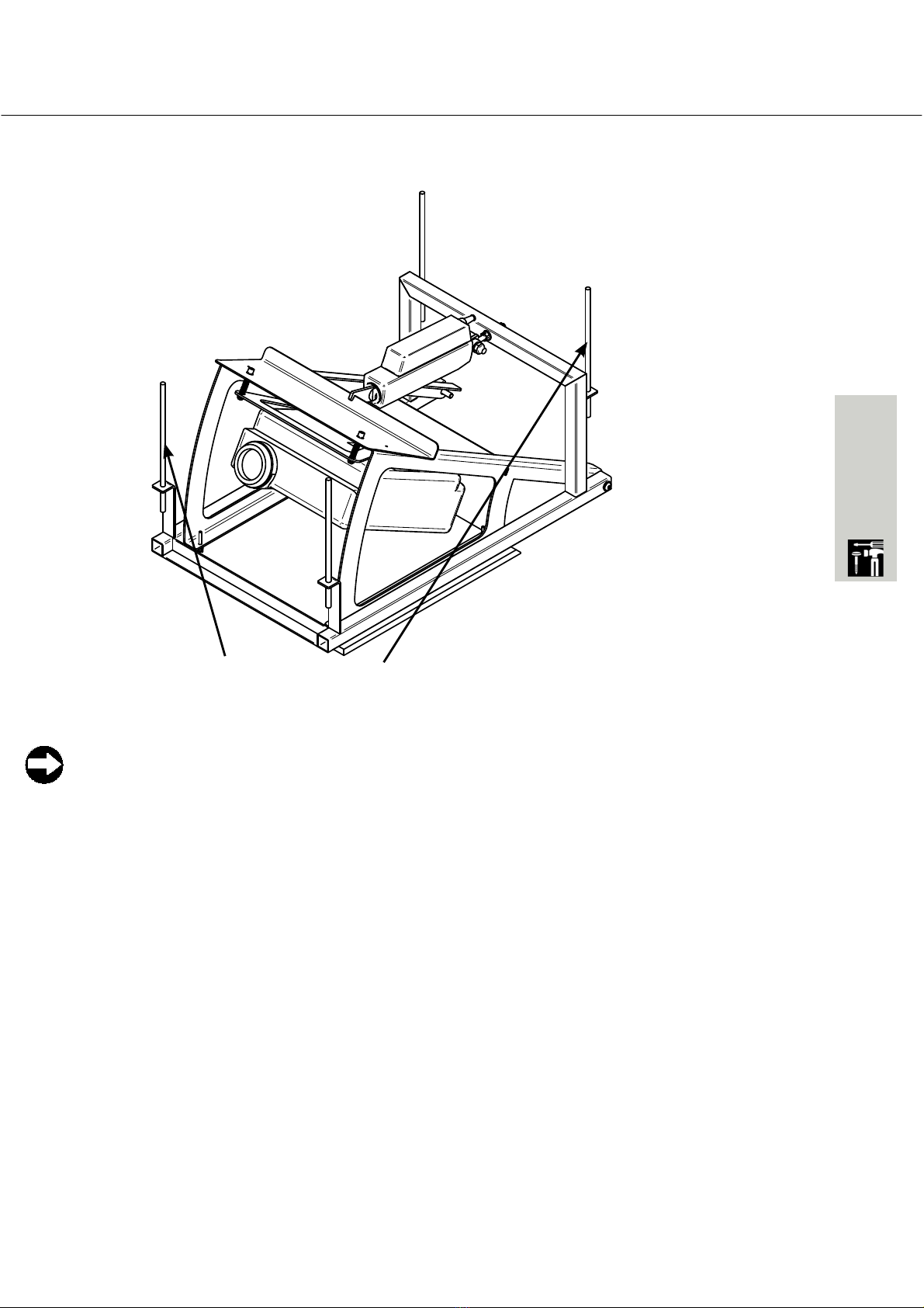
Ceiling Fastening - Suspended Ceiling
For suspended ceilings you can suspend the Dipper itself through the four
mounting holes using threaded rod.
You can use the nuts to adjust the height of the Dipper once
installed, so you can get it exactly flush with the ceiling.
Threaded Rod and Nuts
18 | installation instructions
Mechanical
Installation
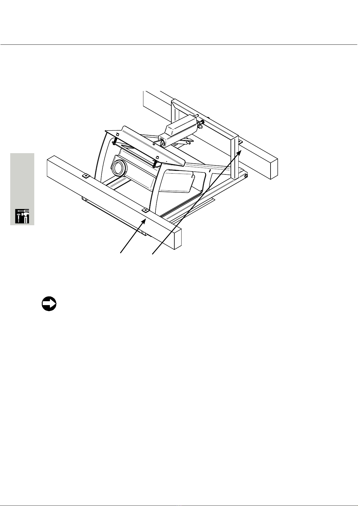
Ceiling Fastening - Trussed Ceiling
For some ceilings, you will need to construct a support structure for the Dipper
to rest in - this can be as simple as two appropriately spaced bearers at the
right height. See the previous pages for the relevant dimensions.
Allow yourself some way to easily adjust the height of the Dipper once
installed, so you can get it exactly flush with the ceiling.
Screwed Straight into Bearers

installation instructions | 19
Mechanical
Installation
Once the Dipper frame is install you should attached the face panel.
We recomend you paint the face panel to match the room before installing it.
1. Insert 4 x countersunk bolts, washers and springs as shown through face panel
from the underside.
2. Adjust the level so that it is exactly flush with the underside of the ceiling.
3. Once full adjusted, cover holes with stick pads. (for more information, refer to
Page 15)
Front
M4 Washer
M4 CS Bolt
Spring
Face Plate Installation
Stick Pad

20 | installation instructions
Electrical
Installation
Electrical Installation
The Dipper is supplied with a unique control unit that can be adapted to just about
any installation requirement.
It operates via dry contacts, but can be easily upgraded to a 12V trigger, Infra Red,
Radio Frequency remote control, or even RS232.
A Maintained, Single Pull, Single Throw Switch (a normal light switch) comes
supplied as standard. or alternatively you can use a single relay. Open circuit is
up, close circuit is down.
You do not need to be a qualified electrician to wire the Dipper, as all circuiting is
24V, however Herma will not accept responsibility for damage incurred by faulty
or incorrect wiring.
The power supply and motor are pre-wired, so all you need to do is attach relay
or motor cable and switch as shown in the following diagram. The switch needs
to be wired into the “Switch Up” and “Common” terminals.
PROTECTIVE ENCLOSURE CONTROL UNIT
POWER SUPPLY + IEC LEAD
WALL SWITCH
Table of contents


