Herutu 21UD User manual

Wired Production Control Indicator
21UD
Instruction Manual V1.70
Please use this Instruction manual correctly on reading well.
Please keep it carefully to be able to read immediately, when required.


[21UD] Notational Conventions for Series Model
Set (Controller+Display)
1
Machine
types
2
Items
3
Communica
tion
4
Display type
5
LED color
21
***
-
***
-
***
-
***
-
***
UD
2
nothing
123
G
UD5
3
485
523
R
UDW
4
429
124
UD5W
524
UDE
152
UDEW
15
12
52
23
24
1523
1524
1. Machine types: UD→Large-sized 4-digit Single side,UD5→Large-sized 5-digit Single side,
UDW→Large-sized 4-digit Double side, UD5W→Large-sized 5-digit Double
side,UDE→Middle-sized 5-digit Single side,
UDEW→Middle-sized 5-digit Double side
2. Item : 2 - 4 items
3. Communication:nothing
429→Specific small-current radio wave
485→Wire-type
4. Display type :1→Target 2→Actual 3→Advancement 4→Accomplishment rate 5→Plan
5. LED color : G→Green, R→Red
*For the Middle-sized type, only red color is available.

To use this product in safety and comfort, (Be sure toread)
Thank you very much for purchasing our product.
This operation manual contains the precautions necessary for preventing an accident caused by the use
in an improper ways.
Read it carefully while thoroughly understanding the meanings of pictorial symbols.
Using in an improper way while ignoring this pictorial symbol might
cause a serious human injury.
Using in an improper way while ignoring this pictorial symbol might cause
a human injury or physical damage.
■The type of precautions that should be observed, are classified using the following pictorial symbols.
This pictorial symbol indicates a “Reminder”to attract an attention.
This pictorial symbol indicates a “Prohibition”to prohibit a certain action.
■For the usage to be commonly applied in all the models:
●Avoid using in a place with a plenty of humidity or dust. Otherwise, absorbing a dust
or water contents may cause machine trouble, fire or electrical shock.
■For handling this machine:
●This is the electronic devise or wireless radios composed of the precision parts.
Do not overhaul/remodel. It may cause accident or machine trouble.
!Warning
!Caution
!
tyuui
!Caution
■For handling this machine:
●Do not use this product for the application needing the high reliability
related to human lives.
●Do not use this product in a place where it is uncertain about whether or
not radio waves reach.
■For handling the power source:
Be sure to observe the following precautions to prevent the AC adapter and Power cord from being
heated, damaged or ignited.
●Do not approximate theAC adapter and Power cord to a fire, or do not put
them into a fire. The AC adapter and Power cord can be broken or ignited,
resulting in an accident.
●You can use theAC adapter and main body only with the specified power
voltage to protect them from the damage and fire accident.
●Do not use theAC adapter and main body in a wettable atmosphere.
It may cause accidents or troubles such as heating, igniting or electrical shock.
●Do not touch theAC adapter, main body, Power cord and Plug outlet with
wet hands. It may cause an electrical shock.
●Do not damage the Power cord.
A short-circuit or heating may cause a fire or electrical shock.
●Do not use the Power plug with dust being adhered.
A short-circuit or heating may cause a fire or electrical shock.
●Do not give a strong impact onto the AC adapter.
It may cause an accident or machine failure.
●If you find out deformedAC adapter, do not use it.
It may cause an accident or machine failure.
●do not use this product in a place where flammable gas can be generated.
It may cause a fire accident.
●Never overhaul theAC adapter.
It may cause an accident or machine failure.
■When trouble happens during use:
Since it may cause a fire or electrical accident, disconnect a power plug, and immediately ask outlet
store or our company torepair.
●When smoke or abnormal odors are generated, stop using, immediately
disconnect a power plug, and ask outlet store or our company torepair.
●Once the Power cord is damaged, do not use it.
Using it as is may cause a fire or electrical accident.
!
!Warning

※This operation manual is translated a product for Japan into English/
This product is based on Japanese Wireless law.

Contents
1. General Description..........................................................................................................1
1-1. Scope...........................................................................................................................1
1-2. Outline .........................................................................................................................1
1-3. Machine types.............................................................................................................1
1-4. Type selection.............................................................................................................2
2. Specifications....................................................................................................................4
2-1. 3-command type.........................................................................................................4
2-2. 2-command type.........................................................................................................6
2-3. 4-command type.........................................................................................................8
2-4. Keyboard...................................................................................................................10
3. Names and Functions of each section .........................................................................12
3-2.Key board...................................................................................................................13
3-2. Terminal block ..........................................................................................................14
4. Setting and Installation methods...................................................................................16
4-1. Installing the Display ...............................................................................................16
4-2. Connecting the Signal cord and Power cord........................................................16
4-2. Installing the Keyboard [KE-2]................................................................................19
5. Function settings ............................................................................................................20
5-1. Setting the operation type Command [1] ........................................................21
5-2. Setting the tact precision Command [2]..........................................................23
5-3. Setting with or without Tact reserve function Command [3] ........................24
5-4. Setting Display way to use Tact reserve function Command [4]..................25
5-5. Setting with or without working hours Command [5]....................................27
5-6. Setting the pre-scale Command [6] .................................................................28
5-7. Setting with/without Advancement judging Command [7]..........................29
5-8. Setting the equipment No. Command[8].........................................................30
5-9. Setting the wireless channel Command[9] .....................................................31
5-10.Setting the stop at the PLAN=ACTUAL Command【F1】 ....................................33
6. Basic operation ...............................................................................................................34
6-1. Setting the Internal clock Key [4].....................................................................38
6-2. Setting the Working hour pattern Key [6]......................................................39
6-3. Setting the Working hour Key [5].....................................................................40
6-4. Setting the Tact Key [0]....................................................................................43

6-5. Setting the contents displaying Key [1]~[3]......................................................44
6-6. Setting the Clear time Key [7].........................................................................47
6-7. Setting the Pre-scale Key [8] ............................................................................49
6-8. Setting the Advancement judging function Key [9] .......................................51
7. Applied operation............................................................................................................53
7-1. Explanation of Working setting ..............................................................................53
7-2. Working setting A - Operation when “No” for working hour setting is
set(Without Tact reserve function) ................................................................................55
7-3. Working setting 2,3,5,6-Setting the Tact reservation (With working hour)........58
8. Handling precautions......................................................................................................65
9. Maintenance.....................................................................................................................66
10. Warranty.........................................................................................................................66
Dimensional drawing..........................................................................................................69

21UD
1
General Description
1. General Description
1-1. Scope
This operation manual describes about Wired Production Control Indicator [21UD]
For the Wired Production Control Indicator with Communication [21UD-429,485], see another
operation manual.
1-2. Outline
The Production Control Indicator unit [21UD] series consists of the Keyboard section
[KE-2]and Indicator section. This machine is Production Control Indicator , which displays the
contents of ever-processing process and the quantity of production at your factory. It helps
you grasp the present status of production at a glance and also provides you with a great
effect on the rationalization of production such as production process analysis, worker’s
self-administration and etc.
1-3. Machine types
Types
Large-sized 21UD
(4-digit and 5-digit display)
Middle-sized 21UDE
(5-digit display)
2-command type
21UD-2
21UDE-2
3-command type
21UD-3
21UDE-3
4-command type
21UD-4
21UDE-4
2-command double side type
21UDW-2
21UDEW-2
3-command double side type
21UDW-3
21UDEW-3
4-command double side type
21UDW-4
21UDEW-4
2-command 5-digit type
21UD5-2
――――
3-command 5-digit type
21UD5-3
――――
4-command 5-digit type
21UD5-4
――――
2-command 5-digit double side
type
21UD5W-2
――――
3-command 5-digit double side
type
21UD5W-3
――――
4-command 5-digit double side
type
21UD5W-4
――――
21UD
2
General Description
1-4. Type selection
The combination of “Target”, “Actual”, “Advancement”, Accomplishment rate”and “Plan”
allows you to select several kinds of types. Normally, the type is already set before shipment.
However, it can be changed after purchasing. You may select the item suitable for your
application after understanding the contents of each item. In this manual, the type is replaced
with the numeric value and alphabet.
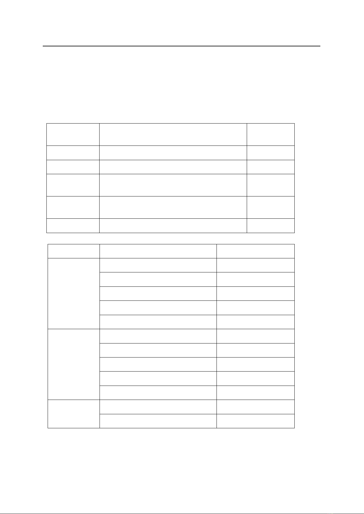
Items
Contents
Numeric
notation
Target
The target quantity of production today
1
Actual
The quantity of production up to the present
2
Advancement
The degree of advancement in either “+”or “-“sign
to the planned quantity of production at the present
3
Accomplishment
rate
The Accomplishment rate (%) of actual to the
planned quantity of production at the present
4
Plan
The planned quantity of production at the present
5
Commands
Types
Numeric representation
3-command
Target/Actual/Advancement
123
Plan/Actual/Advancement
523
Target/Actual/Accomplishment rate
124
Plan/Actual/Accomplishment rate
524
Target/Plan/Actual
152
2-command
Target/Plan
15
Target/Actual
12
Plan/Actual
52
Actual/Advancement
23
Actual/Accomplishment rate
24
4-command
Target/Plan/Actual/Advancement
1523
Target/Plan/Actual/Accomplishment rate
1524

21UD
3
General Description
●How to calculate each item
“Plan”=Elapsed time within working hours ÷Tact
“Accomplishment rate”(%) =(Actual÷Plan) x100
“Advancement”=Actual-Plan
* Decimal places of theAccomplishment rate are all cut off.
* If the Accomplishment rate is over 9999% or it cannot be calculated, “9999”appears for the
calculation results.
21UD
4
Specifications
2. Specifications
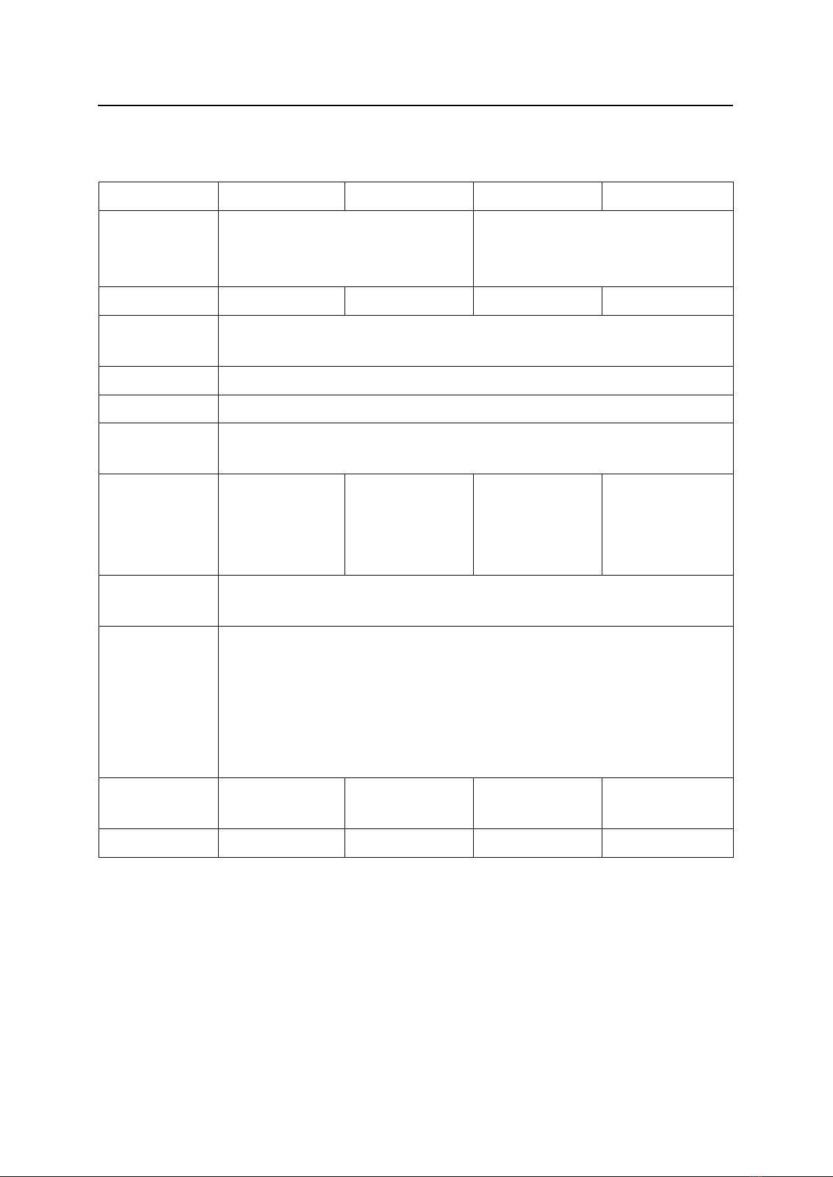
2-1. 3-command type
<3-command large-sized type>
21UD-3
21UDW-3
21UD5-3
21UD5W-3
Indicator
character
(4-digit x 2-line)+(Symbol+ 3-digit x
1-line)
Or 4-digit x 3-line
(5-digit x 2-line) +(Symbol +4-digit x
1-line)
Or 5-digit x 3-line
Display surface
Single side
Double side
Single side
Double side
Indicator
element
High-luminance 7-segment LED display
Character
110H x 60wmm
Size of case
600W x 600H x 80Dmm
Power source
AC100V (Max input range: AC85 –125V)
Power code (2P) VCTF 1.25mm2
Length:approx. 1.5m
Working
environment
Temperature:
0- 50℃
Humidity:85% or
less(no dew drop)
Temperature:
0- 40℃
Humidity:85% or
less(no dew drop)
Temperature:
0- 50℃
Humidity:85% or
less(no dew drop)
Temperature
:0-40℃
Humidity:85% or
less(no dew drop)
Input
Non-voltage contact input x 5-point
For Keyboard unit(KE-2) x 4-point
Output
Open collector output x2-point
Max output voltage DC35V
Max output current 50mA
Relay contact output x 2-point
Max rated relay contact load (resistance load)
AC125V0. 5A or DC24V1A
Power
consumption
MAX47W
MAX88W
MAX58W
MAX111W
Weight
About 9.0kg
About 9.8kg
About 9.2kg
About 10.1kg
21UD
5
Specifications
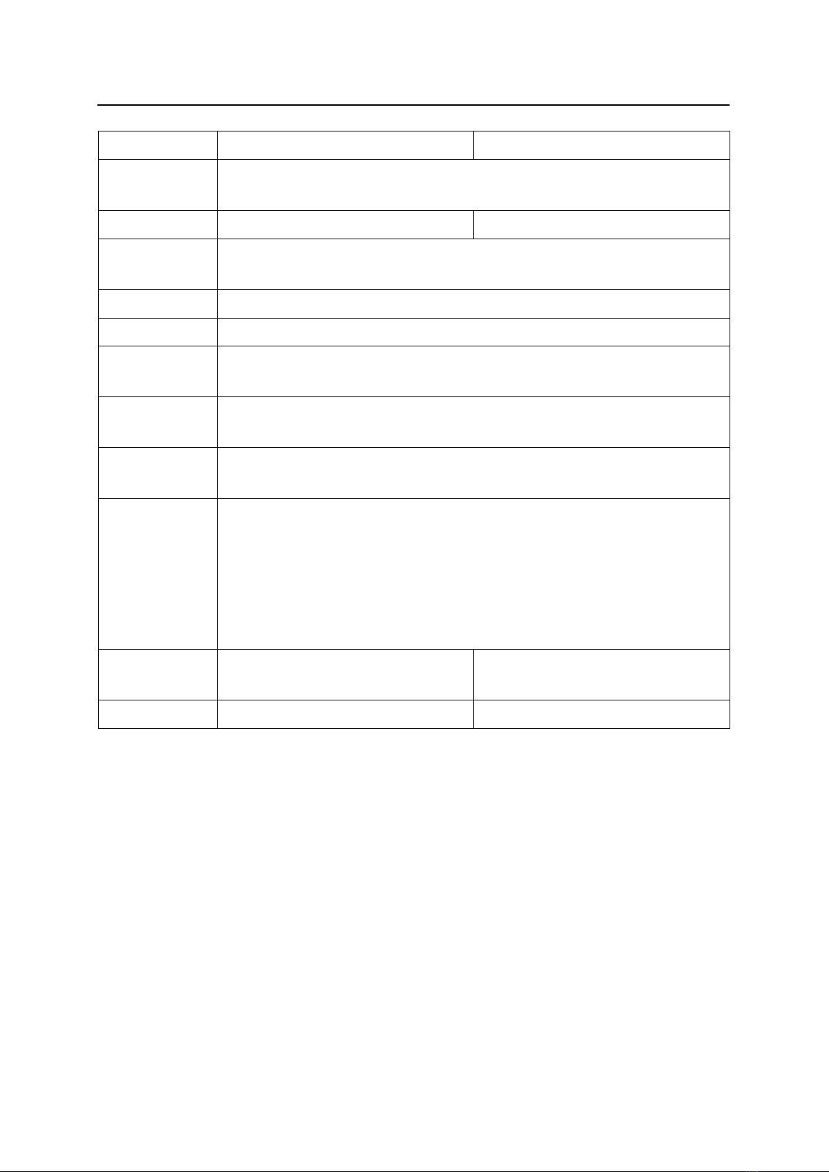
<3-command middle-sized type>
21UDE-3
21UDEW-3
Indicator
character
(5-digit x 2-line)+(Symbol+4-digit x 1-line)
Or 5-digit x 3-line
Display surface
Single side
Double side
Indicator
element
High-luminance dispersion type red-color 7-segment LED
Character
55H x 30Wmm
Size of case
400W x 360H x 65Dmm
Power source
AC100V (Max input range: Ac85 - 125V)
Power code (2P) VCTF 1.25mm2
Length:approx. 1.5m
Working
environment
Temperature: 0-50℃Humidity: 85% or less(no dew drop)
Input
Non-voltage contact input x 5-point
For Keyboard unit(KE-2) x 4-point
Output
Open collector output x2-point
Max output voltage DC35V
Max output current 50mA
Relay contact output x 2-point
Max rated relay contact load (resistance load)
AC125V0.5A or DC24V1A
Power
consumption
MAX19W
MAX34W
Weight
About 4.2kg
About 4.5kg
21UD
6
Specifications
2-2. 2-command type
<2-command large-sized type>
21UD-2
21UDW-2
21UD5-2
21UD5W-2
Indicator
character
(4-digit x 1-line)+(Symbol+3-digit x
1-line)
Or 4-digit x 2-line
(5-digit x 1-line)+(Symbol+4-digit x
1-line)
Or 5-digit x 2-line
Display surface
Single side
Double side
Single side
Double side
Indicator
element
High-luminance 7-segment LED
Character
110H x 60Wmm
Size of case
600W x 445 H x 80Dmm
Power source
Ac100V(Max input range:Ac85 –125V)
Power code (2P) VCTF 1.25mm2
Length:approx. 1.5m
Working
environment
Temperature:0-50℃
Humidity:85% or less (No dew drop)
Temperature:
0-40℃
Humidity:
85% or less (No
dew drop)
Input
Non-voltage contact input x 5-point
For Keyboard unit(KE-2) x 4-point
Output
Open collector output x2-point
Max output voltage DC35V
Max output current 50mA
Relay contact output x 2-point
Max rated relay contact load (resistance load)
AC125V0.5A or DC24V1A
Power
consumption
MAX38W
MAX63W
MAX44W
MAX84W
Weight
About 7.2kg
About 7.6kg
About 7.4kg
About 8.1kg

21UD
7
Specifications
<2-command middle-sized type>
21UDE-2
21UDEW-2
Indicator
character
(5-digit x 1-line)+(Symbol+4-digit x 1-line)
Or 5-digit x 2-line
Display surface
Single side
Double side
Indicator
element
High-luminance dispersion type red-color 7-segment LED
Character
55H x 30Wmm
Size of case
400W x 285H x 65Dmm
Power source
AC100V (Max input range: AC85 - 125V)
Power code (2P) VCTF 1.25mm2
Length:approx. 1.5m
Working
environment
Temperature:0-50℃Humidity:85% or less(No dew drop)
Input
Non-voltage contact input x 5-point
For Keyboard unit(KE-2) x 4-point
Output
Open collector output x2-point
Max output voltage DC35V
Max output current 50mA
Relay contact output x 2-point
Max rated relay contact load (resistance load)
AC125V0.5A or DC24V1A
Power
consumption
MAX15W
MAX25W
Weight
About 3.7kg
About 3.9kg

21UD
8
Specifications
2-3. 4-command type
<4-command large-sized type>
21UD-4
21UDW-4
21UD5-4
21UD5W-4
Indicator
character
(4-digit x 3-line)+(Symbol+3-digit x
1-line)
Or 4-digit x 4-line
(5-digit x 3-line)+(Symbol+4-digit x
1-line)
Or 5-digit x 4-line
Display surface
Single side
Double side
Single side
Double side
Indicator
element
High-luminance 7-segment LED
Character
110H x 60Wmm
Size of case
600W x 755H x 80Dmm
Power source
AC100V (Max input range: AC85 - 125V)
Power code (2P) VCTF 1.25mm2
Length:approx. 1.5m
Working
environment
Temperature:
0-50℃
Humidity:
85% or less(No
dew drop)
Temperature:0-40℃
Humidity: 85% or less(No dew drop)
Input
Non-voltage contact input x 5-point
For Keyboard unit(KE-2) x 4-point
Output
Open collector output x2-point
Max output voltage DC35V
Max output current 50mA
Relay contact output x 2-point
Max rated relay contact load (resistance load)
AC125V0.5A or DC24V1A
Power
consumption
MAX59W
MAX111W
MAX82W
MAX141W
Weight
About 11.0kg
About 12.0kg
About 11.4kg
About 12.4kg

21UD
9
Specifications
<4-command middle-sized type>
21UDE-4
21UDEW-4
Indicator
character
(5-digit x 3-line)+(Symbol+4-digit x 1-line)
Or 5-digit x 4-line
Display surface
Single side
Double side
Indicator
element
High-luminance dispersion type red-color 7-segment LED
Character
55H x 30Wmm
Size of case
400W x 435H x 65Dmm
Power source
AC100V (Max input range:AC85 - 125V)
Power code (2P) VCTF 1.25mm2
Length:approx. 1.5m
Working
environment
Temperature: 0-50℃Humidity:85% or less (No dew drop)
Input
Non-voltage contact input x 5-point
For Keyboard unit(KE-2) x 4-point
Output
Open collector output x2-point
Max output voltage DC35V
Max output current 50mA
Relay contact output x 2-point
Max rated relay contact load (resistance load)
AC125V0.5A or DC24V1A
Power
consumption
MAX24W
MAX44W
Weight
About 5.0kg
About 5.4kg

21UD
10
Specifications
2-4. Keyboard
KE-2
Keyboard
Membrane switch with 20 keys
[F1]-[F4]
[0]-[9]
[▲](UP),[▼](DOWN)
[+],[-]
[CLR],[ENT]
Input/Output
Input power +5v
Output Signal key1
Signal key2
Common GND
Size of case
120W x 100H x 35Dmm
Weight
About 550g
Communication
cable
4 cores cable(with shield,0.2 mm2
) Length:approx. 5m

21UD
11
Specifications
Operating specifications
Items
With working hour
Without working hour
Labor hour
Max 23 hours 59 minutes
Max 1 month
Working hour
For 20 working hours
Number of sets: 40
Impossible to set
Working hour
pattern
6 patterns
Impossible to set
Tact
0.1-9999.9 second or 0.01-999.99 second
Target
4-digit type:0-9999 5-digit type:0-99999
Plan
4-digit type:0-9999 5-digit type:0-99999
Actual
4-digit type:0-9999 5-digit type:0-99999
Advancement
4-digit type:0-±999 5-digit type:0-±9999
Accomplishment
rate
4-digit type:0-999(%) 5-digit type:0-9999(%)
Tact reservation
For twenty types at max
<Reserved contents>
Set-up time 0-998-min *1
Tact 1-9999.9 second or 0.01-999.99 second
Production target quantity 4-digit-type:0-9999 5-digit-type:0-99999
Clear time
For 3-time max
Pre-scale value
1-99999(Multiple number) 1-99999(Batch number)
Advancement
judging set value
0-9999(+side) 0-9999(-side)
*1:It can be set only when Working hour setting “Yes”is set.
*Internal clock may possible cause approximately 1-min/month in error depending on the working
environment(0 to 50℃).

21UD
12
Names and Functions of each section
3. Names and Functions of each section
①Fitting
To hang display 2-point
②Signal code eject hole
To draw signal cord
③Power cord eject hole
To draw power cored.
(The product is shipped with Power cord being mounted.)
④Power lump
Illuminated at power on
⑤Power switch
Switch to supply power
⑥Fuse
Fuse
⑦Acrylic plate
Differrent from Type (Shipment time fixation)
⑧Screws for removing
acrylic plate
Screws for removing acrylic plate
⑨Side panel
Fixed main body with4 pieces.
①Fitting
④Power switch
③Power cord eject hole
⑥Fuse
⑦Acrylic plate
⑧Screws for removing
acrylic plate(4 pieces on
both sides)
⑨Side panel(L)
⑨Side panel (R)
②Signal code eject hole
⑤Power lump
This manual suits for next models
8
Table of contents
Other Herutu Measuring Instrument manuals


