Herutu SD-4 User manual

Compact Production Control Indicator
【SD-4】
Operation Manual
V1.50


FCC for United States ofAmerica
NOTE:
This equipment has been tested and found to comply with the limits for a Class A digital device,
pursuant to Part 15 of the FCC Rules. These limits are designed to provide reasonable protection
against harmful interference when the equipment is operated in a commercial environment.
This equipment generates, uses, and can radiate radio frequency energy and, if not installed and
used in accordance with the instruction manual, may cause harmful interference to radio
communications. Operation of this equipment in a residential area is likely to cause harmful
interference in which case the user will be required to correct the interference at his own expense.
IC for CANADA
This classA digital apparatus compliance with Canadian ICES-003.
Cet appareil numérique de la classeA est conforme à la norme NMB-003 du Canada.

CONTENTS
Chapter 1 Before Use.................................................................................................................. 1
1-1 Introduction........................................................................................................................ 1
1-2 Accessories........................................................................................................................ 1
1-3 Safety precautions (Be sure to read)............................................................................... 1
1-4 General description........................................................................................................... 3
1-5 Specifications..................................................................................................................... 4
1-6 Exterior features ................................................................................................................ 5
1-6-1 Main body .................................................................................................................... 5
1-6-2 Terminal block............................................................................................................. 6
1-7 Dimensional drawing......................................................................................................... 7
1-8 Installation.......................................................................................................................... 8
1-8-1 Installation procedure ................................................................................................ 8
1-8-2 Input terminal block.................................................................................................... 8
Chapter 2 How to Use.................................................................................................................. 9
2-1 Function settings............................................................................................................... 9
2-1-1 Setting an operation type..........................................................................................11
2-1-2 Setting use or no use of the Working hour............................................................ 13
2-1-3 Setting the stop input logic ..................................................................................... 14
2-1-4.Setting use or no use of the function which plan stop at Target....................... 15
2-2 Basic operations.............................................................................................................. 16
2-2-1 Initial screens............................................................................................................ 17
2-2-2 Setting the Internal clock......................................................................................... 18
2-2-3 Setting the Working hour pattern............................................................................ 20
2-2-4 Setting the Working hour......................................................................................... 21
2-2-5 Setting the Tact ......................................................................................................... 26
2-2-6 Setting the Target...................................................................................................... 27
2-2-7 Setting the Plan......................................................................................................... 28
2-2-8 Setting the Actual...................................................................................................... 29
2-2-9 Setting the Advancement......................................................................................... 30
2-2-10 Setting the Accomplishment rate.......................................................................... 32
2-2-11 Setting the Clear time............................................................................................. 33
2-2-12 Post-setting tests.................................................................................................... 34
2-3 Description of the function keys.................................................................................... 35
2-4 Stop function.................................................................................................................... 36
2-5 MONITOR LED (operating status LED).......................................................................... 37
2-6 Error messages................................................................................................................ 38

Chapter 3 Handling Information............................................................................................... 39
3-1 Handling precautions...................................................................................................... 39
3-2 If something is wrong...................................................................................................... 40
3-3 Warranty............................................................................................................................ 40
1
1-1 Introduction
This operation manual contains necessary information for using the product, such as general
description, installation, and operation of the product.
Read the manual carefully before using the product. Also, keep it at a safe place for ready
reference at anytime.
1-2 Accessories
Mounting fittings: 1 set
Nameplate stickers (Japanese): 1 set
Fixture for wire fixing:1 piece
1-3 Safety precautions (Be sure to read)
The description here highlights the precautionary matters which must be strictly observed in
order to prevent physical harm to the user or other persons and damage to the property.
The following pictorial symbols are used to classify and explain the criticality levels of harms or
damages that may result from using the product in an improper way while ignoring the
instructions.
The Caution indication means that “failure to observe the instructions
may result in human injury, or physical damage alone.”
For handling this machine:
This machine is a wireless communication device composed of precision parts.
Do not overhaul/remodel. It may cause an accident or a machine trouble.
For working/storage environment:
To minimize the possibility of trouble, characteristic degradation, fire, or electrical
shock, avoid using or storing the product in the following locations:
•Locations subject to direct sunlight.
•Locations where liquids, foreign objects, corrosive gas, or flammable gas may
enter the product.
•Locations exposed to high humidity, oily smoke, dust, sand, or the like.
•Locations with less stability such as the top surface of an unsteady table or an
inclined surface.
The Warning indication means that “failure to observe the instructions
may result in death or serious injury.”
For handling this machine:
Do not use this product for such applications as require an extremely high level
of reliability relating to human life.
Do not use this product in locations where there is uncertainty about the
coverage of radio waves.
Chapter 1 Before Use
!
Caution
Prohibited
Prohibited
Prohibited
!
Warning
Prohibited

2
For handling the power supply:
Always observe the following precautions to prevent the power cord from being heated,
damaged, or ignited.
Do not bring the power cord close to fire nor put it into fire. The power cord
may be broken or ignited, resulting in an accident.
Use the AC adapter and the main body only with the specified power voltage to
protect them against damage or fire accidents.
Do not use the main body in a wettable atmosphere. It may cause accidents or
troubles such as heating, igniting, and electrical shock.
Do not touch the main body, the power cord, or the plug outlet with wet hands.
It may lead to accidents such as electrical shock.
Do not damage the power cord. A short circuit or heating may result, causing
fire or electrical shock.
Do not use the power plug with dust adhered on it. A short circuit or heating
may result, causing fire or electrical shock.
Do not give a strong impact onto the power cord.
It may cause an accident or a machine trouble.
Do not use the power cord if you find out deformation etc. in it.
It may cause an accident or a machine trouble.
Do not charge the main body in locations where flammable gas could be
generated.
It may result in igniting or a fire accident.
Never overhaul the main body.
It may cause an accident or a machine trouble.
When something erroneous has occurred during use:
Since it may cause fire, electrical shock, or the like, remove the power plug from the plug
outlet and ask the outlet store or us for repair.
When smoke or abnormal odors come out, immediately remove the power plug
from the plug outlet and ask the outlet store or us for repair.
Do not use the power cord if it is damaged.
Using the damaged power cord may result in fire or electric shock.
Prohibited
Prohibited
Prohibited
Prohibited
Prohibited
Prohibited
Prohibited
Prohibited
Prohibited
Prohibited
Attention
Prohibited

3
1-4 General description
This machine is a compact type indicator unit that displays the constantly changing production
quantity on the shop floor. It helps you grasp the ongoing status of production at a glance and
also contributes greatly to the rationalization of production such as analysis of manufacturing
processes and improvement of workers’self-control.
With a built-in microprocessor, the machine allows you to set or change the six types of basic
data: Tact, Target,Actual, Advancement, Clock, and Working hour.
As for a production quantity, the machine counts up the signals from limit switches etc.,
calculates the advancement based on the tact and working hours, and displays each of the
data. The machine also features a number of functions, which include the “Clear time
function”for automatically clearing the Plan, Actual, and Advancement when a preset time is
reached, and the “Stop function” for temporarily suspending the Plan calculation even during
working hours.
Low in price.
Compact, lightweight, and space-saving.
Bright & easy-to-see 1-inch red color 7-segment LED display.
Equipped with a built-in microprocessor and a timer.
Offers a range of display variations and allows you to change display types by keyboard
operation.
Includes the stop function.
Includes the data backup function, which allows data to be maintained even at a power
failure.
Can select between use and no use of the Working hour.
When the Working hour is not used, a switchover is made between the operating and
stopped status in response to ON/OFF of external contact inputs.

4
1-5 Specifications
Items
Specifications
Input
Non-voltage contact input x 2:
• Actual count x 1
• Stop input x 1
Display
4-digit x 3-line Single-sided
High-luminance 7-segment LED Character height: 25.4mm
Operating status monitor LED x 1:
・LED colors: 2 (red/green) *1
Power LED x 1
Switch
Power switch x 1
Operating power
voltage
DC12V (input voltage range: DC11 - 15V) / 0.8A or more
Operating power
supply
DC jack
Applicable plug: φ2.1(I.D.) x φ5.5(O.D.) mm Center negative
Power consumption
200mA (at DC12V)
Working
environment
Temperature: 0-50˚C Humidity: 80% or less (no condensation)
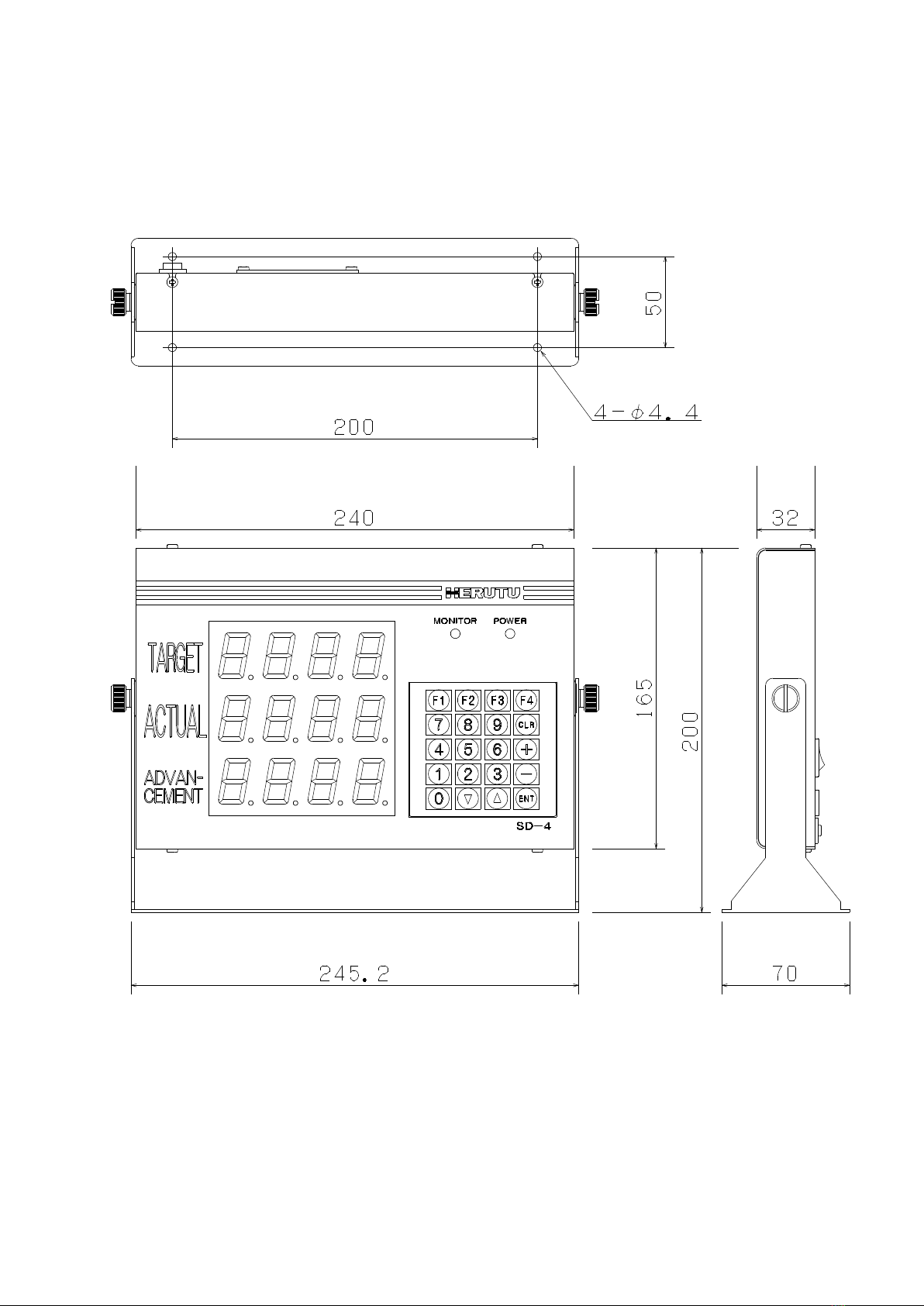
Dimensions
240(W) x 165(H) x 32(D) mm (projections excluded)
Weight
1.5kg
Clock backup
Approx. 5 years Coin type lithium battery (CR2032)
<Operating specifications>
Items
Specifications
Labor hour
Max 23 hours 59 minutes/day *2
Working hour
For 20 working hours (periods)/day *2
Working hour
pattern
6 patterns *2
Tact
0.1-9999.9 seconds
Target
0-9999
Plan
0-9999
Actual
0-9999
Advancement
-999 - +999
Accomplishment
rate
0-999
Clear time
3 times/day
cumulative operat-
ing time limitation
Cumulative operating time for no use of Working hour: Max 1 month
*1: The term “orange”used in the following refers to the color produced by simultaneous
emission of red and green LED’s.
*2: Specifications for use of the Working hour.

5
1-6 Exterior features
1-6-1 Main body
Items
Descriptions
POWER LED
Illuminates at power on.
MONITOR LED
(LED for operating)
LED for checking the operating status.
Illuminates in “red”/“green”/“orange” depending on the operating status.
Keyboard
Keyboard for operations.
Data display
4-digit x 3-line 7-segment LED display.
Power switch
Power-on/off switch.
Terminal block
Input terminal block for the Actual count/stop.
DC jack
DC12V input
Applicable plug: φ2.1(I.D.) x φ5.5(O.D.) mm, center negative
Mounting stay
Dedicated stay for installation.
FCC label
FCC Note for a Class A digital device or peripheral
POWER LED
MONITOR LED (for operating)
Keyboard
Data display
Power switch
Terminal
block
DC jack
Mounting stay
Mounting
stay
FCC label

6
1-6-2 Terminal block
The terminal block is located on the back of the main body. The functions of individual
terminals are shown below.
Terminal
Input
Function
GND
―――
Common GND
COUNT
UP
Input
Actual count input. (Actual + 1 per signal input)
GND
―――
Common GND
STOP
Input
Input terminal for stop/operating. (Stop input terminal)
* For each input terminal, connect a non-voltage contact.
7
1-7 Dimensional drawing
8
1-8 Installation
1-8-1 Installation procedure
(1) Mount the mounting stay to the installation area with wood screws or small screws.
Mount the main body onto the mounting stay with ornamental screws loosely tightened.
* In the case the mounting stay is attached to the main body, remove the two ornamental
screws from both sides and detach the mounting fittings.
(2) To the Actual count (UP terminal) on the input terminal block, connect the non-voltage
contact for counting up the input signals from relays, micro switches, limit switches, etc.
Also, establish a connection to each of the other input terminals as needed.
(3) Determine the angle at which the display panel (data display and LED’s) is easy to see
and operate, and then fix the main body by fully tightening the ornamental screws on
both sides.
(4) Insert an applicable plug firmly into the DC jack and supply the power of DC12V/0.8A or
more. (Applicable plug: φ2.1(I.D.) x φ5.5(O.D.) mm with center negative)
The main body has a build-in microprocessor, which means there is a possibility that the data
may collapse due to power fluctuation or flicker. Take power supply from a location free from
power fluctuation or flicker.
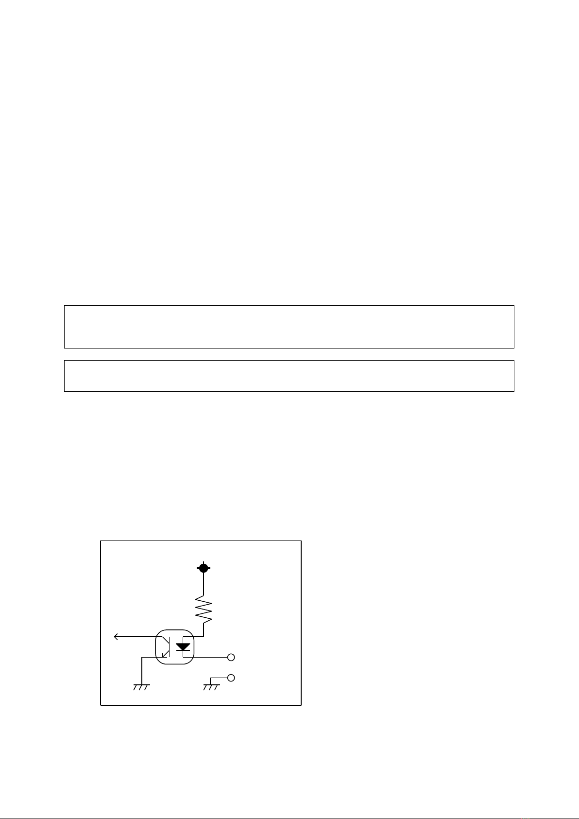
For the non-voltage contacts to be connected to the input terminal block, use the ones with less
chattering that can steadily turn on/off the voltage/current of 12V/10mA.
1-8-2 Input terminal block
For the input signals to be connected to the terminal block, use the ones with less chattering
that can steadily turn on/off the voltage/current of 12V/10mA. Keep a time interval of at
least 50msec between input signals. Also, keep 50msec or more from when one input
signal is turned off till another input signal is turned on.
<Input circuit>
Non-voltage contact input circuit (rating: DC12V/10mA)
R
フォトカプラ COM
INPUT
+12V
Photocoupler

9
Chapter 2 How to Use
2-1 Function settings
Before using the machine, you need to make settings for the following items. Read the
description carefully and make suitable settings for your intended application.
Setting an operation type
Select an item shown on the display of the machine to set a desired operation type.
For an operation type, you may make a choice from among the seven patterns in all by a
combination of “Target,”“Actual,”“Advancement,” “Accomplishment rate,”“Plan,”and “Tact.”
Setting use or no use of the Working hour
When the Working hour is used, the machine calculates the planned quantity based on the
registered data of working hours.
When the Working hour is not used, the machine calculates the planned quantity based on
ON/OFF of external input signals.
Setting the stop input logic
Set “Positive” or “Negative” for the logic of a stop input signal.
The resulting operation (operating/stop) differs depending on whether the Working hour is set
to be used or not used.
Setting
Terminal input
Working
hours
Stop input logic
ON
OFF
Used
Negative
Stop
Operating
Positive
Operating
Stop
Not used
Negative
Operating
Stop
Positive
Stop
Operating
■Setting use or no use of the function which the planned quantity stop at Target.
Setting use or no use of the function which the planned quantity calculation stop, when the
planned quantity reached target.
When choosing the operation type which includes target of display “Plan“,
“Advancement“and “Accomplishment rate“can’t be set any more.
(The case of setting “1”)

10
How to call up the function settings screen
Turn on the power switch while pressing the [F1] key. The [Function settings screen]
appears after the [Initial screen 1] is displayed for about 1.5 seconds.
On the [function settings screen] shown above, select the following sub commands to make
your settings.
* Default values
The factory settings are as follows:
Operation type: → 123 (Target/Actual/Advancement)
Use/no use of Working hour: → Used
Stop input logic: → Negative logic
Use or no use of the function
which the planned quantity stop at Target →Not used
*
*.
*
Program version
[Initial screen 1]
F
1
[Function settings screen]
Sub
command
Description
Setting
1
Sets an operation type.
Select from seven patterns.
2
Sets use/no use of the Working hour.
0: Not used
1: Used
3
Sets the stop input logic.
0: Negative logic
1: Positive logic
4
Setting use or no use of the function
which the planned quantity stop at Target.
0: Not used
1: Used
About 1.5 sec. later

11
2-1-1 Setting an operation type
The machine is so designed that a setting can be made from among seven operation types.
When using the machine with any operation type other than the type 123
(Target/Actual/Advancement), affix the attached command sticker onto the case.
Display items [1] Target: The target production quantity of the day (fixed
value).
[2]Actual: The production quantity up to the present time.
[3]Advancement: The degree of advancement relative to the
planned production quantity at the present
time.
[4]Accomplishment rate: The rate of accomplishment to the planned
production quantity at the present time.
[5] Plan: The planned production quantity at the present
time (changes over time).
[6] Tact: The time required for production per product
(shown in seconds).
Operation type
Description
*123
Target/Actual/Advancement
523
Plan/Actual/Advancement
124
Target/Actual/Accomplishment rate
524
Plan/Actual/Accomplishment rate
152
Target/Plan/Actual
126
Target/Actual/Tact
526
Plan/Actual/Tact
* Default values
<How to set>
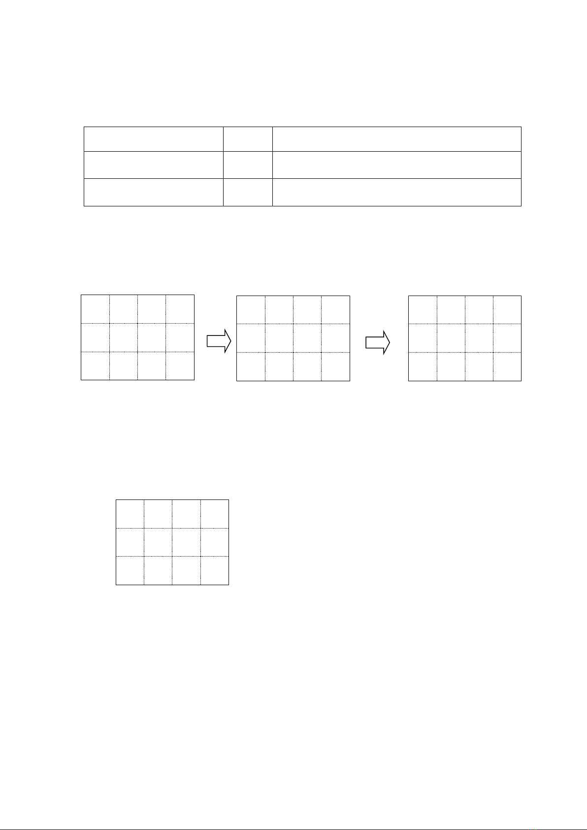
(1) On the function settings screen, press the [1] key on the keyboard.
The currently set operation type appears after the sub command “C1” is displayed for
0.75 seconds.
F
1
[Function settings screen]
C
1
The sub command is
displayed.
*
*
*
The set operation type
appears.

12
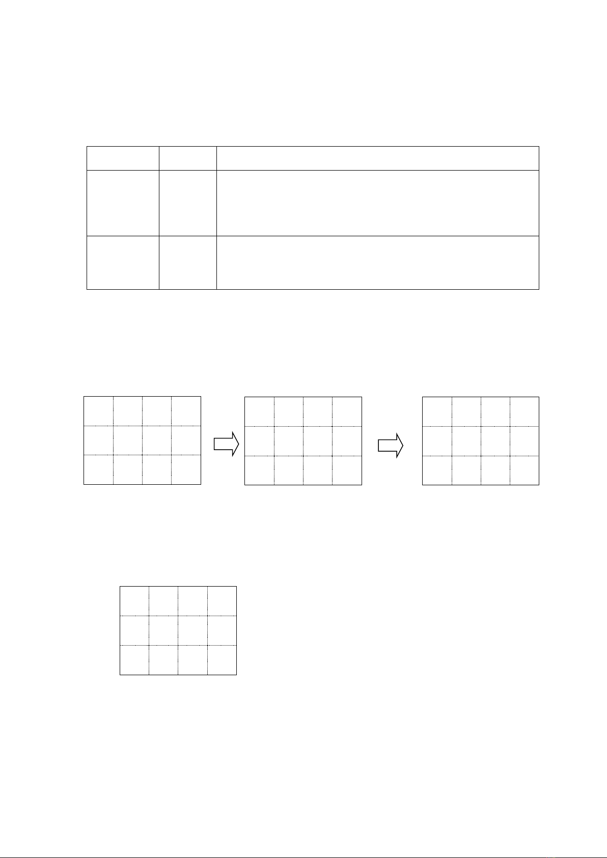
(2) Input the operation type of your choice with a 3-digit number. For example, to set the
type 523, input [5][2][3]. The resulting display is as follows:
(3) Press the [ENT] key to set the operation type you input. If you have inadvertently press
a wrong type No., press the [CLR] key and re-input the correct data.
* * * Error * * *
If you have input any number other than the type Nos. and pressed the [ENT] key, then an
error will result. In this case, the display blinks the following screen and automatically
returns to the re-input status without changing the preset type.
The operation type you set appears on the last three digits of the top line on the [Initial screen
2] (see page 17).
5
2
3
1
0
0
13
2-1-2 Setting use or no use of the Working hour
This machine is so designed that use or no use of the Working hour can be set.
Note that the resulting operation differs depending on whether the Working hour is set to be
used or not used.
Setting
Set value
Description
Working
hour:
Not used
0
[5] (Register working hour) and [6] (Select working hour pattern)
are disabled.
The Plan calculation is carried out based on the status of external
input signals.
No recalculation function is available.
*Working
hour:
Used
1
[5] (Register working hour) and [6] (Select working hour pattern)
are enabled.
The Plan calculation is carried out based on the registered data of
working hours.
*Default values
<How to set>
(1) When on the function settings screen, press the [2] key on the keyboard.
The currently set value appears after the sub command “C2” is displayed for 0.75
seconds.
(2) As the value you want to set, input either [0] (Not used) or [1] (Used).
<e.g.> To set the Working hour to be used, input [1]. The resulting display is as follows:
(3) Press the [ENT] key to set the change you input. If you have inadvertently input a
wrong data, press the [CLR] key and re-input the correct data.
F
1
[Function settings screen]
C
2
The sub command is
displayed.
*
The set value appears.
1

14
2-1-3 Setting the stop input logic
The machine is so designed that the logic of a stop input signal can be set to either “Negative
logic” or “Positive logic.” Note that the resulting operation differs depending on whether the
Working hour is set to be used or not used.
Setting
Set value
Description
Negative logic
*0
See the table below.
Positive logic
1
See the table below.
* Default values
Setting
Terminal input
Working hour
Stop input logic
ON
OFF
Used
Negative
Stop
Operating
Positive
Operating
Stop
Not used
Negative
Operating
Stop
Positive
Stop
Operating
<How to set>
(1) When on the function settings screen, press the [3] key on the keyboard.
The currently set value appears after the sub command “C3” is displayed for 0.75
seconds.
(2) As the value you want to set, input either [0] (Negative logic) or [1] (Positive logic).
<e.g.> To set the stop input logic to Negative logic, input [0]. The resulting display is as
follows:
(3) Press the [ENT] key to set the value you input. If you have inadvertently set a wrong
data, press the [CLR] key and re-input the correct data.
F
1
[Function settings screen]
C
3
The sub command is
displayed.
*
The set value appears.
0
15
2-1-4.Setting use or no use of the function which plan stop at Target.
Setting use or no use of the function which the planed quantity calculation stop when plan
reached target. It can use that choosing the type which includes target of display.
Setting
Set
value
Description
Plan=Not stop at target
※0
Plan=Plan doesn’t stop when plan reached target.
Plan>Plan indication is possible.
Plan=stop at target
1
Plan=Plan stops when plan reached target.
Plan>Plan indication is not possible.
※Default values.
<How to set>
①When on the function settings screen, press the [4] key on the keyboard.
The currently set value appears after the sub command “C4” is displayed for 0.75 seconds.
②As the value you want to set, input either [0] (Not used) or [1] (Used).
To set the Plan calculation stopped when the plan reached target to be used, input [1].
The resulting display is as follows:
③Press the [ENT] key to set the change you input. If you have inadvertently input a wrong
data, press the [CLR] key and re-input the correct data.
※When choosing the operation type which includes target of display 「Plan」「Advancement」
「Accomplishment rate」can’t be set any more.
(The case of setting “1”)
F
1
[Function settings screen]
C
4
The sub command is
displayed.
*
The set value appears.
1
Table of contents
Other Herutu Measuring Instrument manuals


Popular Measuring Instrument manuals by other brands

Martin
Martin N2 operating instructions

Keller
Keller CellaTemp PK Series quick start guide

Bosch
Bosch ABC 150 operating instructions

PCB Piezotronics
PCB Piezotronics 320C03 Installation and operating manual

Halma
Halma Sensitron SMART 3 NC Short installation manual

Isspro
Isspro EV Installation instructions manual


