Herutu AN426RM II User manual

1mW Wireless Call Systems
[AN426RMⅡ]
Instruction Manual
V1.10


CONTENTS
1. Before Use.............................................................................................................................................. 1
1-1. Introduction...................................................................................................................................... 1
1-2. Main Unit and Accessories.............................................................................................................. 2
1-3. Safety Precautions (Be Sure to Read This).................................................................................... 3
1-4. Outline ............................................................................................................................................. 5
1-5. System Configuration...................................................................................................................... 6
1-6. Specification .................................................................................................................................... 7
1-6-1. Transmitter AN426TⅡ.............................................................................................................. 7
1-6-2. Receiver AN426RMⅡ.............................................................................................................. 7
1-7. Part Names and Descriptions ......................................................................................................... 8
1-7-1. Transmitter AN426TⅡ.............................................................................................................. 8
1-7-2. Receiver AN426RMⅡ.............................................................................................................. 8
1-8. Dimensional Drawing ...................................................................................................................... 9
1-8-1. Transmitter AN426TⅡ.............................................................................................................. 9
1-8-2. Receiver AN426RMⅡ.............................................................................................................. 9
1-9. Installation...................................................................................................................................... 10
1-9-1. Notes for Installation............................................................................................................... 10
1-9-2. Installation of Transmitter ....................................................................................................... 10
1-9-3. Installation of Receiver........................................................................................................... 10
1-9-4. Input / Output Terminal Block..................................................................................................11
1-9-5. Input Circuit............................................................................................................................. 12
1-9-6. Output Circuit.......................................................................................................................... 12

2. Settings................................................................................................................................................. 13
2-1. Transmitter Settings ...................................................................................................................... 13
2-2. Receiver Settings.......................................................................................................................... 13
2-2-1. Channel, Set No. and Unit No. Settings................................................................................. 15
2-2-2. Display Method Setting........................................................................................................... 16
2-2-3. Output Time Setting................................................................................................................ 16
3. Description of Operation ...................................................................................................................... 17
3-1. Transmitter Operation.................................................................................................................... 17
3-2. Receiver Operation ....................................................................................................................... 18
3-2-1. Basic Operation...................................................................................................................... 18
3-2-2.Receiver Test Operation......................................................................................................... 20
4. Speaker (Option).................................................................................................................................. 21
4-1. Speaker Operation ........................................................................................................................ 21
4-2. Sound Selection ............................................................................................................................ 22
5. Troubleshooting.................................................................................................................................... 24
6. After service and Warranty................................................................................................................... 25

1
1. Before Use
1-1. Introduction
This instruction manual contains necessary information for using the product, such as general
description, installation, and operation of the product. We thus ask that you read the manual
carefully before proceeding to use the product and keep it available at hand for ready reference
whenever you need it.
This product consists of the transmitter(s) “AN426TII” (hereinafter “transmitter”) and a receiver
“AN426RMⅡ” (hereinafter “receiver”). Up to eight transmitters are available.
The transmitter of this system is a device certified to comply with the technical standards for “radio
equipment for specified low-power radio stations telemeter & telecontrol.”
< Information on radio equipment for telemeter & telecontrol >
Radio equipment for telemeter:
Refers to radio equipment which is intended to utilize radio waves to automatically display or
record the measurement results of a remotely located measuring instrument.
Radio equipment for telecontrol:
Refers to radio equipment which is intended to utilize radio waves to transmit the signals for
starting, changing, or stopping the functions of a remotely located device.
1. Do not use this system for any applications that could cause harm or damage to human life
or to other equipment or devices. Also, do not use it in the vicinity of any devices that could
malfunction due to the radio waves from the transmitter.
2. Disassembling or making modification to any equipment or devices certified to comply with
the technical standards is prohibited by law.
3. The casing of the transmitter bears a certification label for compliance with the technical
standards. Do not remove the label from the casing of the transmitter. Using the transmitter
with the certification label removed is prohibited by law.
4. This equipment is exclusively for use in Japan.
It may not be used outside Japan because the applicable radio law is only effective in Japan.
Besides, it may not be used in a condition that it is connected with an electrical
communication line.
5. The communication performance varies depending on the ambient environment. Before
installation, ensure that the installation location is within the coverage.

2
1-2. Main Unit and Accessories
■Transmitter AN426TⅡ
For main unit and accessories of the transmitter, see the instruction manual “Specified
Low-power 1mW Transmitter AN426TⅡ.”
■Receiver AN426RMⅡ
Receiver main unit AN426RMⅡ×1
Antenna TK-1597 ×1

3
1-3. Safety Precautions (Be Sure to Read This)
This section describes the matters to be observed in order to prevent harm to the users and other
persons and damages to the property.
■The following marks and displays classify and describe the extent of harm and damage caused by
failing to observe the display content and using this product wrongly.
This display column shows "a failure to do observe it could result in death
or serious personal injury".
This display column shows "a failure to do observe it could result in only
the personal injury or property damage".
■Common matters in handling
●Avoid using this product in the humid or dusty place. Dusts or water enters the product,
which may cause the fault, fire, or electric shock.
■Handling this product
●This product is the wireless communication equipment made of precision parts. Do not
disassemble or modify it. Or the accident or fault may occur.
■Handling this product
●Do not use this product for application that requires the extremely high reliability
affecting the human life.
●Do not use this product in the area which the radio wave reaches or not.
■Handling the power supply
Be sure to observe the followings in order to prevent the accidents such as heat generation,
damage, or ignition of AC adapter and power cord.
●Do not place the AC adapter and power cord close to fire or insert them into fire. Or
they may be burst and ignited, resulting in the accident.
●Use the AC adapter and main body only at the specified power supply voltage in order
to prevent burst and ignition accidents.
! Warning
! Caution
! Caution
! Warning
4
●Do not use the AC adapter and main body at the location where they easily get wet. Or
the accidents including heat generation, ignition, or electric shock and faults may occur.
●Do not touch the AC adapter, main body, power cord, and outlet with wet hands. Or the
accident such as an electric shock may occur.
●Do not damage the power cord. Short-circuit or heat generation may cause fire or
electric shock.
●Do not use the power plug with dusts attached. Short-circuit or heat generation may
cause fire or electric shock.
●Do not give a strong shock to theAC adapter.
Or the accident or fault may occur.
●If you find a deformation in theAC adapter, do not use it.
Or the accident or fault may occur.
●Do not charge the main body at the location where the flammable gas is generated.
Or the ignition accident may occur.
●Never disassemble the AC adapter.
Or the accident or fault may occur.
■Never disassemble the AC adapter.
Remove the power plug from the outlet because it may cause fire and electric shock. Request the
dealer or our company to repair it.
●When smoke comes or there is a strange smell, immediately stop usage and remove
the power plug from the outlet because it may cause fire and electric shock. Request the
dealer or our company to repair it.
●If the cord is damaged, do not use it. Using the cord damaged continuously may cause
fire or electric shock.
■Reliability of wireless communication
As wireless communication has properties that are different from those of wired communication,
communication errors may occur due to the following.
・Exceeds the communication distance.
・Enters a dead zone.
・Interfered by strong jamming
If signals are often jammed, or being jammed leads to operational problems, stop using the
systems and restart using the systems after removal of the cause.
Radio waves may not be received due to various reasons other than the above. Please understand
this before using the systems.
*A dead zone is an area where the radio wave transmitted from the transmitter becomes extremely
weak due to radio waves reflected from walls or other objects.

5
1-4. Outline
1. You can monitor up to eight trouble occurrence reports with a single receiver and eight
transmitters AN426TⅡ.
At the transmitter, there are two selectable input methods: one with four push buttons (1
(orange), 2 (red), 3 (green), 4 (white)) and one with four external inputs (1 (orange), 2 (red),
3 (green), 4 (white)). According to possible trouble occurrences in the production line, you
can assign each color a meaning, such as red for an exception occurrence, orange for parts
out of stock, green for requesting transportation of finished products, or white for trouble
solved.
The indicator with the same number as the kiki number set in the transmitter lights up (or
blinks).
2. The receiver performs the external outputs (open collector outputs and relay output) in
synchronization with the lighting (or blinking) of the indicator.
3. Since the communication channels can be set from 1CH to 10CH, interference can be
prevented even when multiple receivers are installed.
In addition, 10 set numbers and 10 unit numbers can be set for each channel, so it is
possible to identify up to 1,000 receivers.
* The transmitter and the receiver are shipped with the same communication channel, set
number, and unit number set.
4. The receiver is a double-sided display type.
5. You can select the display method of the indicator from lighting or blinking. It is possible to
set the display method for push button input and external input individually. For the display
method, refer to “2-2-2. Display Method Setting”.
6. In addition to the indicator lights, an optional speaker can be installed that enables sound
notifications. A different melody for each indicator color can be configured (when multiple
colors are illuminated, the melody is selected according to the priority order). For details on
the speaker, refer to “4. Speaker (Option)”.
6
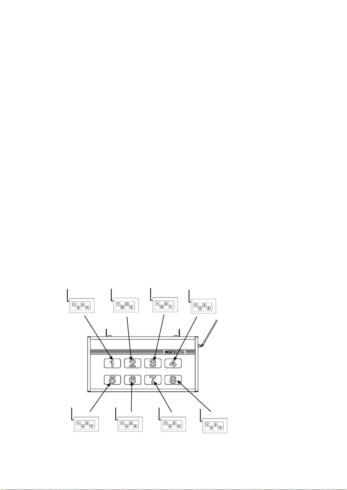
AN426RHⅡcan be used in combination with eight AN426TⅡtransmitters.
Kiki No.1
Kiki No.2
Kiki No.3
Kiki No.4
Kiki No.5
Kiki No.6
Kiki No.7
Kiki No.8
AN426TⅡ
AN426RMⅡ
1-5. System Configuration
This product consists of the following devices.
1. 1mW transmitter AN426TⅡ
At the transmitter, there are two selectable input methods: one with four push buttons (1
(orange), 2 (red), 3 (green), 4 (white)) and one with four external inputs (1 (orange), 2 (red),
3 (green), 4 (white)). The transmitter transmits a radio signal according to the input signal.
For details on the transmitter, refer to the instruction manual for “Specified Low-power 1mW
Transmitter AN426TⅡ”.
2. Receiver AN426RMⅡ
•The receiver lights up (or blinks) each indicator independently for corresponding calls
from the transmitter. The indicator numbers 1 to 8 correspond to the kiki numbers set in
the transmitter. The indicator can be displayed in three colors: orange, red, and green.
•The receiver performs 4 open collector outputs and 1 relay output in synchronization with
the lighting (or blinking) of the indicator. The output time can be selected from
“continuous” or “5 seconds”. For the output time, refer to “2-2-3. Output Time Setting”.
This system supports calling distant people and machines of the production line.

7
1-6. Specification
1-6-1. Transmitter AN426TⅡ
For details on the transmitter, refer to the instruction manual for “Specified Low-power 1mW
Transmitter AN426TⅡ”.
1-6-2. Receiver AN426RMⅡ
Item
Specification
Frequency Band
426.0250MHz - 426.1375MHz (12.5kHz steps - 10 channels)
Type of Radio Wave
F1D
Antenna
λ/4 Whip Antenna
Modulation System
Direct 2-FSK Modulation
Modulation Speed
977bps
Communication
Receive only
Outputs
4 Open Collector Outputs (Max. Rated Load DC 35V 50mA)
1 Relay Output (Photo MOS relay) (Max. Related Load AC/DC 30V 0.5A)
Inputs
2 Non-voltage Contact-Inputs
1 Reset ALL / 1 Reset Output * Output: Open collector outputs / Relay output
Indicator Element
8 Indicator Lamps (Indicator Dimensions (H×W) 50×90 mm (2.0×3.5″))
Double-Sided Indicator
3-Color LED (Orange, Red, Green)
* For orange, the color tone may slightly vary.
Power Source
AC 100V (AC 100-120V)
Wattage
Max.33W
External Dimensions
(W×H×D) 600 × 300 × 80 mm (23.6×11.8×3.1″)
(except any protruding object such as an antenna)
Weight
Approx. 5.8 kg
*The weight of the receiver with an optional speaker is approx.1.7kg heavier than
that of a receiver without a speaker.
Operating
Environment
Temperature:0 - +40℃(32-104°F)
Humidity:85% or less (without condensation)
Setting Switches
1 Switch (8-Position DIP)
3 Switches (10-Position Rotary each) (for setting Channel, Set No., Unit No.)
Included
1 Antenna
8
FUSE
1-7. Part Names and Descriptions
1-7-1. Transmitter AN426TⅡ
For details on the transmitter, refer to the instruction manual for “Specified Low-power 1mW
Transmitter AN426TⅡ”.
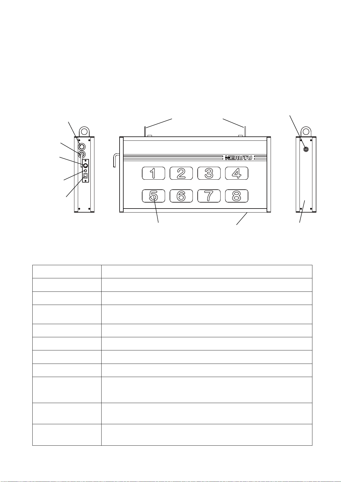
1-7-2. Receiver AN426RMⅡ
Item
Description
Mounting bracket
Use the mounting metal fittings for fixing the receiver.
BNC connector
Connects the included antenna.
Signal line take-out hole
Connect the signal lines to the internal input/output terminal block by drawing
them through this takeout hole.
Power cable
Power cable with a plug (approx. 1.5 m)
Fuse
AC125 V fuse. (For fuse capacity, see the affixed seal.)
Power lamp
Lamp for the power source. Lights up when the power source is switched on.
Power switch
Power switch of the main unit.
Indicator
3-Color LED (Orange/ Red/ Green). The receiver illuminates each indicator
independently for corresponding calls from the transmitter. The indicator
corresponding to the kiki No. of the transmitter lights up (or blinks).
Side panel
Remove the side panel to connect signal lines to the input/output terminal block
or configure Channel, Unit No., Set No. and Display method.
Setting label
Label showing factory default Channel/ Set No./ Unit No.
e.g. “1-0-2” :Channel 1/ Set No. 0/ Unit No. 2
Mounting bracket
BNC connector
Signal line take-out hole
Power cable
Fuse
Power lamp
Power switch
Indicator
Side panel
Setting label
9
1-8. Dimensional Drawing
1-8-1. Transmitter AN426TⅡ
For details on the transmitter, refer to the instruction manual for “Specified Low-power 1mW
Transmitter AN426TⅡ”.
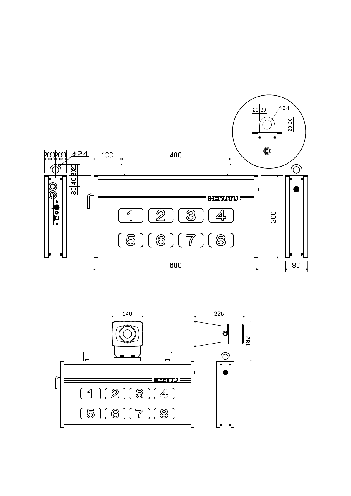
1-8-2. Receiver AN426RMⅡ
Option (AN426RMⅡ-MRD)
*The weight of the receiver with an optional speaker is approx.1.7kg heavier than that of a
receiver without a speaker. Please be careful when installing.
Mounting bracket
10
1-9. Installation
1-9-1. Notes for Installation
When installing the product, pay attention to the following:
1. Keep the antenna away from metal sheets or wires and do not set it alongside the side panel
of the annunciator.
2. Keep the antenna away from noise sources.
3. For installation, choose a location where there are no shielding objects between the
antennas of the transmitter and the annunciator.
4. The communication performance largely depends on the installation environment. Before
installation, make sure if the installation location is within the coverage.
5. This system (transmitter and annunciator) is not dust-proof or drip-proof in construction.
* For installation, avoid choosing such locations as:
•Within reach of direct sunlight
•In the presence of an extremely high level of moisture
•In the vicinity of TV or radio
•In the vicinity of sparking devices such as a welding machine
•In the presence of an intense magnetic field
•In an area surrounded by iron frames or metallic walls
1-9-2. Installation of Transmitter
For details on the transmitter, refer to the instruction manual for “Specified Low-power 1mW
Transmitter AN426TⅡ”.
1-9-3. Installation of Receiver
Install the receiver where it can be seen easily and clearly from the transmitter. When using the
mounting fittings, secure the receiver to a location stable enough to support the weight (approx.
5.8 kg).
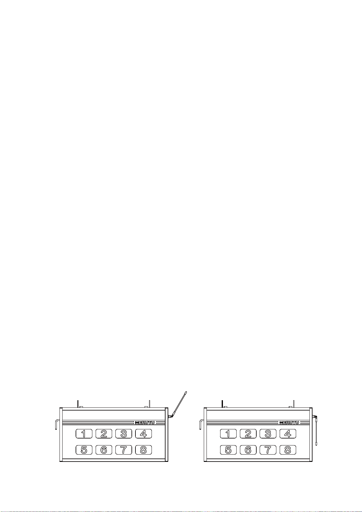
Direct the antenna diagonally upward. Do not direct it downward in parallel with the side of the
receiver.
Good
Bad
11
腉鏼韍苍隳鍤袳苅
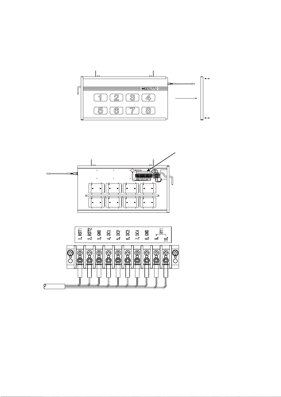
1-9-4. Input / Output Terminal Block
External outputs in synchronization with LED illumination are generated at the input/output
terminal block inside.
Set the antenna perpendicular to the side panel and remove the screws (4) securing the side
panel. Move the side panel off the main unit while taking care not to hitch it on the antenna.
As the input/output terminal block is on the back side, remove the acrylic sheet on the back by
sliding it out.
Inside of the receiver (back)
Input/output terminal block
1.RST1 :All reset input (Returns the settings to default.)
2.RST2 : Output reset input (Stop external output.)
4.OC1 : Open collector output (Synchronized with orange LED illumination.)
5.OC2 : Open collector output (Synchronized with red LED illumination.)
6.OC3 : Open collector output (Synchronized with green LED illumination.)
7.OC4 : Open collector output (Synchronized with orange/ red/ green LED illumination.)
9/10.RY1 : Relay output (Synchronized with orange/ red/ green LED illumination.)
Pass the signal lines through the signal line takeout hole before connecting it to the terminal block.
*Input/output terminal block: M3 screw
Input/output terminal block

12
Photocoupler
Terminal Block
5V
GND
RST 1,2
Transistor
Terminal Block
OC1-4
GND
RY1
RY1
Terminal Block
Photo MOS Relay
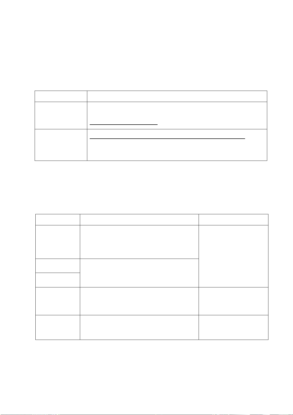
1-9-5. Input Circuit
For the Non-voltage contact input to be connected to the “All Reset” Input and “Output Reset”
Input, use the circuit with less chattering which can steadily turn on/off the voltage/current of
DC5V/15mA.
Reset Input Circuit
1-9-6. Output Circuit
The maximum rated load of open collector output is DC35V 50mA.
Open Collector Output circuit
The maximum rated load of relay output is AC/DC30V 0.5A.
Relay Output Circuit
13
2. Settings
2-1. Transmitter Settings
For details on how to set the transmitter, refer to the instruction manual for “Specified Low-power
1mW Transmitter AN426TⅡ”. When you use the transmitter(s) in combination with this product,
set the operation mode and the kiki number as follows:
Item
Configuration content
Operation mode
The transmitter has two operation modes: AN426TⅡmode and AN426T
mode (earlier mode).
Select the AN426TⅡmode.
Kiki number
Set the kiki number of the transmitter within the range of 1 to 8.
The kiki numbers 0 and 9 are not available.
The receiver lights up (or blinks) the indicator with the same number as the
kiki number of the transmitter.
2-2. Receiver Settings
The receiver has the following setting items.
*Please turn off the power before changing the settings.
Item
Description
Reference item
Channel
Since channels can be set from 1CH to 10CH,
interference can be prevented even when
multiple receivers are installed.
Configure the receiver channel to match the
transmitter.
2-2-1. Channel, Set No. and
Unit No. Settings
Set No.
This is a setting to identify the receiver.
Configure the receiver settings to match the
transmitter.
Unit No.
Display method
Set the display method (lighting or blinking) of the
indicator. This setting can be configured
separately for push buttons and external inputs.
2-2-2. Display Method
Setting
Output time
Set the open collector output time and relay
output time.
2-2-3. Output Time Setting
14
NO
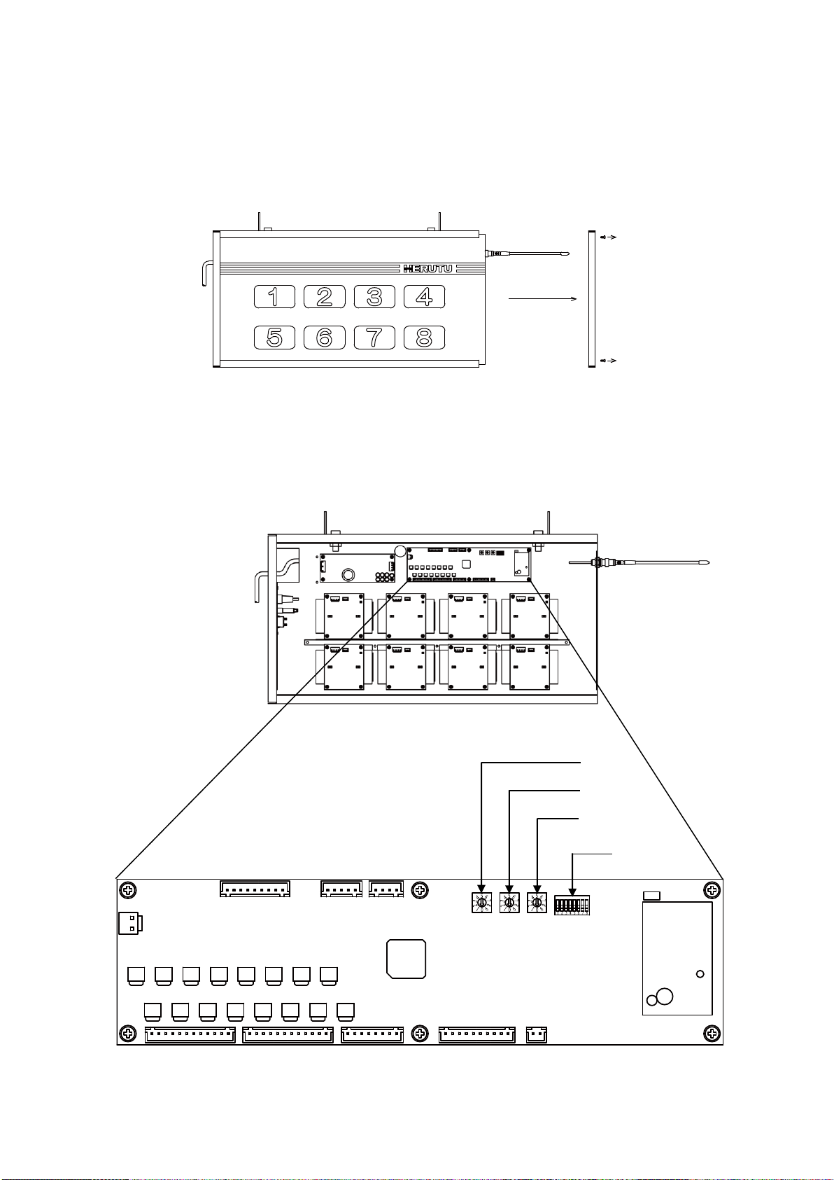
Configure each setting using the RSW1, RSW2, and RSW3 (rotary switches 1-3) and the DSW1
(DIP switch 1) on the CPU board inside the receiver.
Set the antenna perpendicular to the side panel and remove the screws (4) securing the side
panel. Move the side panel off the main unit while taking care not to hitch it on the antenna.
As the CPU board is in the front, remove the front acrylic sheet by sliding it out.
Inside of the receiver (Surface)
CPU board
RSW1
RSW2
RSW3
DSW1
15
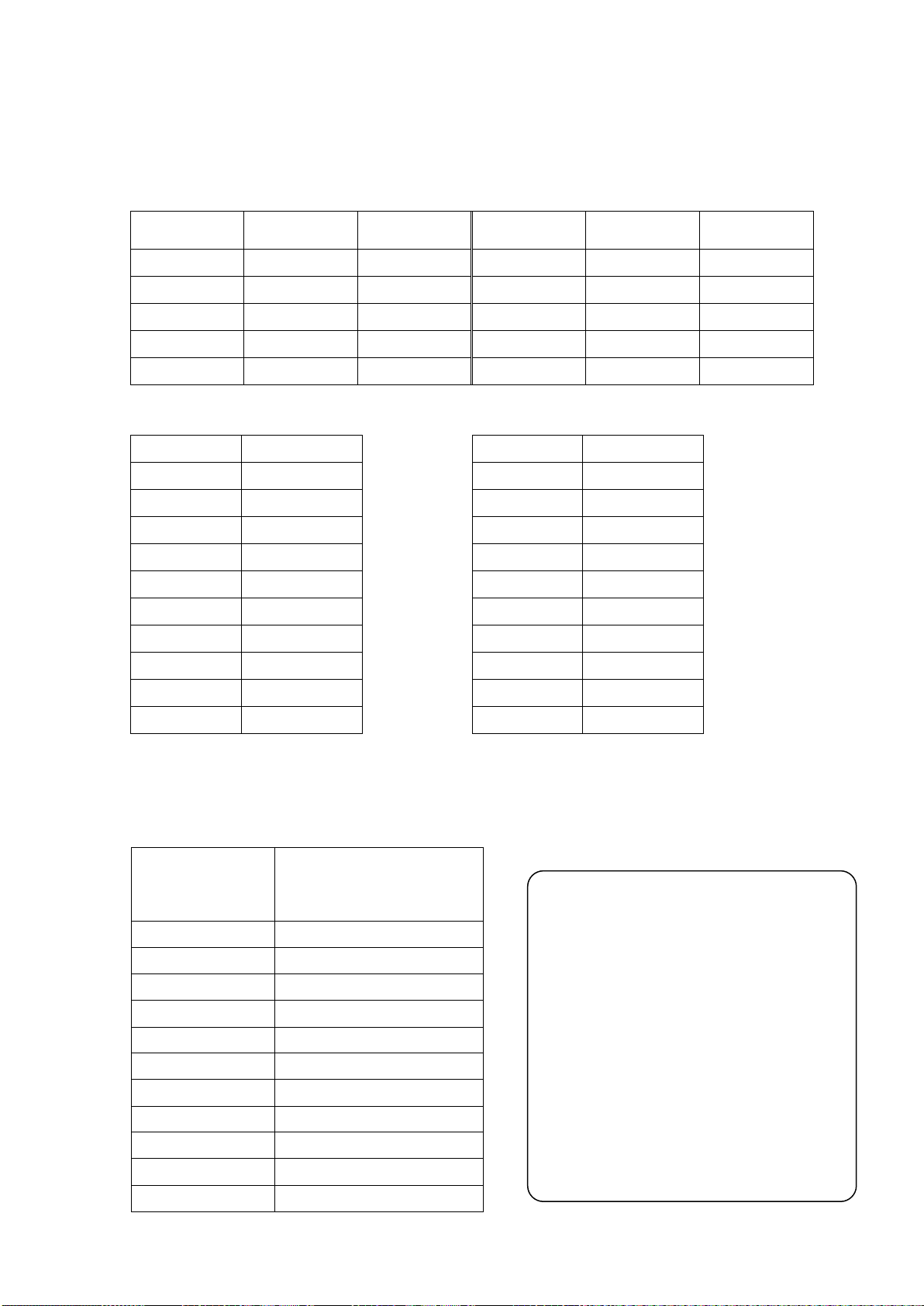
2-2-1. Channel, Set No. and Unit No. Settings
Configure the settings of the channel, the set number, and the unit number to match the
transmitter.
< Channel >
RSW1
Channel
Frequency
(MHz)
RSW1
Channel
Frequency
(MHz)
1
1
426.0250
6
6
426.0875
2
2
426.0375
7
7
426.1000
3
3
426.0500
8
8
426.1125
4
4
426.0625
9
9
426.1250
5
5
426.0750
0
10
426.1375
< Set No. > < Unit No. >
RSW2
Set No.
RSW3
Unit No.
0
0
0
0
1
1
1
1
2
2
2
2
3
3
3
3
4
4
4
4
5
5
5
5
6
6
6
6
7
7
7
7
8
8
8
8
9
9
9
9
The setting of the channel, the set number, and the unit number can be confirmed by the
lighting pattern of the indicator at power on. The indicators light in the order of the channel
(green), the set number (orange), and the unit number (red).
Channel (1-10)
Set No. (0-9)
Unit No. (0-9)
Lighting pattern
0
All indicators light up
1
Indicator 1 lights up
2
Indicator 2 lights up
3
Indicator 3 lights up
4
Indicator 4 lights up
5
Indicator 5 lights up
6
Indicator 6 lights up
7
Indicator 7 lights up
8
Indicator 8 lights up
9
Indicator 1 and 8 light up
10
Indicator 2 and 8 light up
Example of display:
Channel 9
Set No. 4
Unit No. 0
Channel: Indicator 1 and 8 light up in green
↓
Set No.: Indicator 4 lights up in orange
↓
Unit No.: All indicators light up in red

16
2-2-2. Display Method Setting
Set the display method using the DSW1-1 and DSW1-2.
The display method can be configured separately for push buttons and external inputs.
Status of the DSW1-1
OFF
ON
Push buttons
Lighting
Blinking
Status of the DSW1-2
OFF
ON
External inputs
Lighting
Blinking
2-2-3. Output Time Setting
Set the open collector output time and relay output time using the DSW1-3.
You can select from the following two output times.
・Continuous output ・・・・・・・The receiver outputs continuously in synchronization with lighting
(or blinking) of the indicator.
・Output for 5 seconds ・・・・・The receiver outputs for 5 seconds in synchronization with
lighting (or blinking) of the indicator.
Status of the DSW1-3
OFF
ON
Output time
Continuous
5 seconds
*Please do not change DSW1-4, DSW1-5, DSW1-6, DSW1-7 and DSW1-8.
Changing the factory settings may cause the receiver to malfunction.
Table of contents
Other Herutu Receiver manuals

Herutu
Herutu WCL-426R User manual

Herutu
Herutu TW-510R User manual

Herutu
Herutu TW-800R-SC User manual

Herutu
Herutu TW-800R-EXS User manual

Herutu
Herutu TW-800 Series User manual

Herutu
Herutu TW-800R-EXP User manual

Herutu
Herutu TW-800R-EXL User manual

Herutu
Herutu TW-800R-MCL User manual

Herutu
Herutu WCL-920R User manual

Herutu
Herutu TW-800R-EXS User manual


