Herutu TW-800R-MCL User manual

Simple Pokayoke Counter TW-800R-SCL
Mobile Pokayoke Counter TW-800R-MCL
Transmitter TW-800T
INSTRUCTION MANUAL V1.30
Please use this operation manual correctly on reading well.
Please keep it carefully to be able to read immediately, when required.

Table of Contents
■1.Outline .................................................................................................................................................................1
■2.Body and Accessories.......................................................................................................................................2
■3.Safety Precautions (Be Sure to Read This).....................................................................................................5
■4.Name of Each Part..............................................................................................................................................9
4-1.Receiver..........................................................................................................................................................9
4-2.Transmitter...................................................................................................................................................11
■5.Installation.........................................................................................................................................................12
5-1.Transmitter...................................................................................................................................................12
5-2.Receiver........................................................................................................................................................15
5-2-1.External output - Judge output (PASS /FAIL)....................................................................................16
5-2-2.External input - Work-Select input / Judge/Sensor input / Reset input..........................................17
■6.Startup of the receiver .....................................................................................................................................19
■7.Setting ...............................................................................................................................................................19
7-1.Pairing (Registration)..................................................................................................................................19
7-2.Selection of operating mode......................................................................................................................20
7-3.Settings With Web Server...........................................................................................................................21
7-3-1.Connecting to Web server...................................................................................................................21
7-3-2.Setting account.....................................................................................................................................22
7-3-3.Setting network information................................................................................................................23
7-3-4. Advanced settings...............................................................................................................................24
■8.Test switch ........................................................................................................................................................31
■9.Battery level notification function ..................................................................................................................32
■10.Stand-alone mode..........................................................................................................................................33
10-1.Registering Work in the receiver.............................................................................................................33
10-2.Operation....................................................................................................................................................35
■11.Application interlock mode ...........................................................................................................................37
11-1.Buzzer volume adjustment.......................................................................................................................37
11-2.Installation Methods..................................................................................................................................37
11-3.Confirmation of the connection status with the application ................................................................38
11-4.Operation....................................................................................................................................................38
■12.Simple count mode ........................................................................................................................................39
12-1.Setting.........................................................................................................................................................39
12-2. Operation...................................................................................................................................................39
12-3.Buzzer volume adjustment.......................................................................................................................39
■13.Ethernet Communication ..............................................................................................................................40
13-1.LAN cable connector.................................................................................................................................40
13-2.Communication Specification..................................................................................................................41
■14. Setting backup/restore to USB memory.....................................................................................................45
14-1. Backup.......................................................................................................................................................45
14-2.Restore .......................................................................................................................................................46
■15.Specifications .................................................................................................................................................47

■16.Dimensions Drawing......................................................................................................................................48
■17.Troubleshooting .............................................................................................................................................52
■18.After service and Warranty ...........................................................................................................................55

1
Transmitter
Receiver
■1.Outline
TW-800R-SCL and TW-800R-MCL (hereinafter called “the receiver”) is a receiver with wireless function and a
simple counting function.
The receiver is used one-to-one with various tools equipped with TW-800T (hereinafter called “the transmitter”).
The transmitter can be mounted on the torque wrench with a limit switch, the check pen, the pliers wrench, the
cordless power tool, etc., and a completion signal such as tightening can be wirelessly transmitted to the receiver.
This instruction manual explains about TW-800T as a transmitter. It also covers the functions of the firmware
version V2.00 of the receiver. To check the firmware version of your receiver, see “6. Startup of the receiver”.
With the receiver, you can select one of three operating modes: “stand-alone mode”, “application interlock mode”
or “simple count mode”. When using the receiver by itself, select “stand-alone mode”or “simple count mode”.
When using the receiver in combination with Production Process Support Software for Pokayoke Tools
“POKAYOKE plus*1”, select “application interlock mode”.
In the “stand-alone mode”, the receiver counts up or down when receiving a signal from the transmitter. When
Auto judge is ON, as soon as the predetermined specified count value is reached, the receiver notifies you with
“sound” and “display” as well as generating a PASS output to external devices. When Auto judge is OFF, the
receiver judges that the specified count value is reached when a Judge input is received.
Select and use the following functions: Function to Output Task Results Data to LAN, Judge by work timer,
Sensor Input Function to Enable Counting, Work number display, RESET-key disabled, and continuous output of
PASS/FAIL.
In the "simple count mode" the receiver only counts up when receiving a signal from the transmitter and does not
judge. The maximum count is 999.
In the “application interlock mode”, you can log and save task results for each work by linking with POKAYOKE
plus via LAN. This also facilitates building a Pokayoke system that covers multiple processes.
Activate TW-800R-SCL by connecting it to the included AC adapter, and TW-800R-MCL by connecting the
included DC jack cable to the USB power supply.
*1: POKAYOKE plus is a Windows-compatible application that can be used in conjunction with a Pokayoke
receiver capable of a LAN connection.

2
■2.Body and Accessories
Receiver
●TW-800R-SCL
●TW-800R-MCL
TW-800R-SCL body ×1
AC Adapter ADB24050 (Cable 1.5m (4.9ft))
USB(A)/DC Adapter Cable DC-4017A
(Cable 1.2m (3.9ft))
TW-800R-MCL body ×1
3
Transmitter
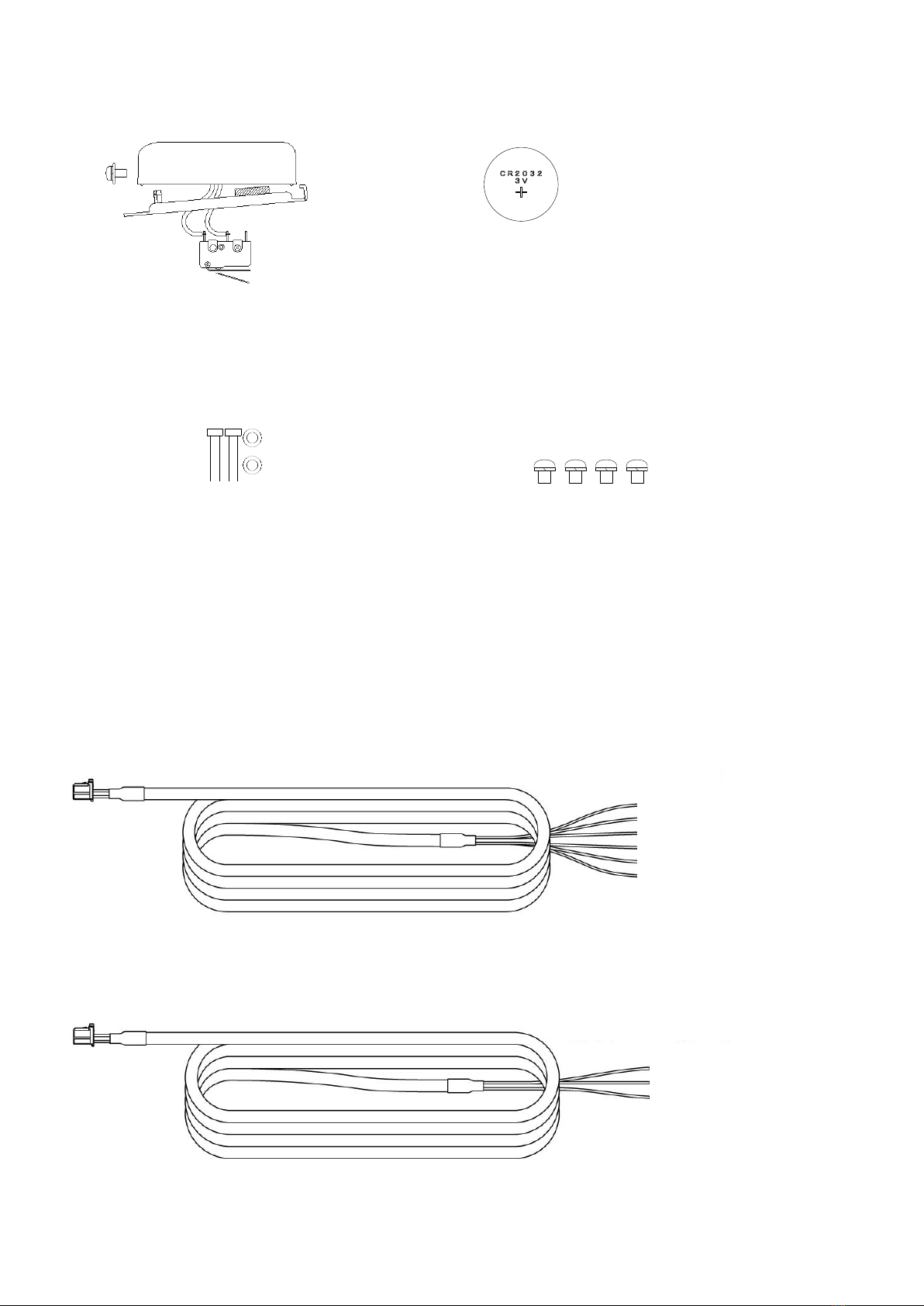
●TW-800T
Extra cost option
The options for the receiver can commonly be used on the TW-800R-SCL and TW-800R-MCL.
・TW-800R-SCL Input Cable TW-SCLI-6 (Cable 1.8m (5.9ft))
Cable to input the Work-Select/Judge/Reset signal from external devices.
・TW-800R-SCL Output Cable for JUDGE TW-SCLO-4 (Cable 1.8m (5.9ft))
Coin battery: CR2032 ×1
Mounting screw M4 x L5 ×4pcs
TW-800T body ×1
(Body mounting screw M3 x L7 ×1pc, Harness connector with limit switch TW-800T-HCL ×1pc)
Mounting bracket ×1
For limit switch
Hexagon socket head bolt M2 × L10 ×2pcs
Flat washer M2 (φ2.2) ×2pcs
1. Red (JUDGE input)
2. Red / White (Reset input)
3. Green (Work-Select input 1)
4. Green / White (Work-Select input 2)
5. Black / White (Work-Select input 3)
6. Black (COM)
1. Red (PASS output)
2. Red / White (FAIL output)
4. Black (COM)
4
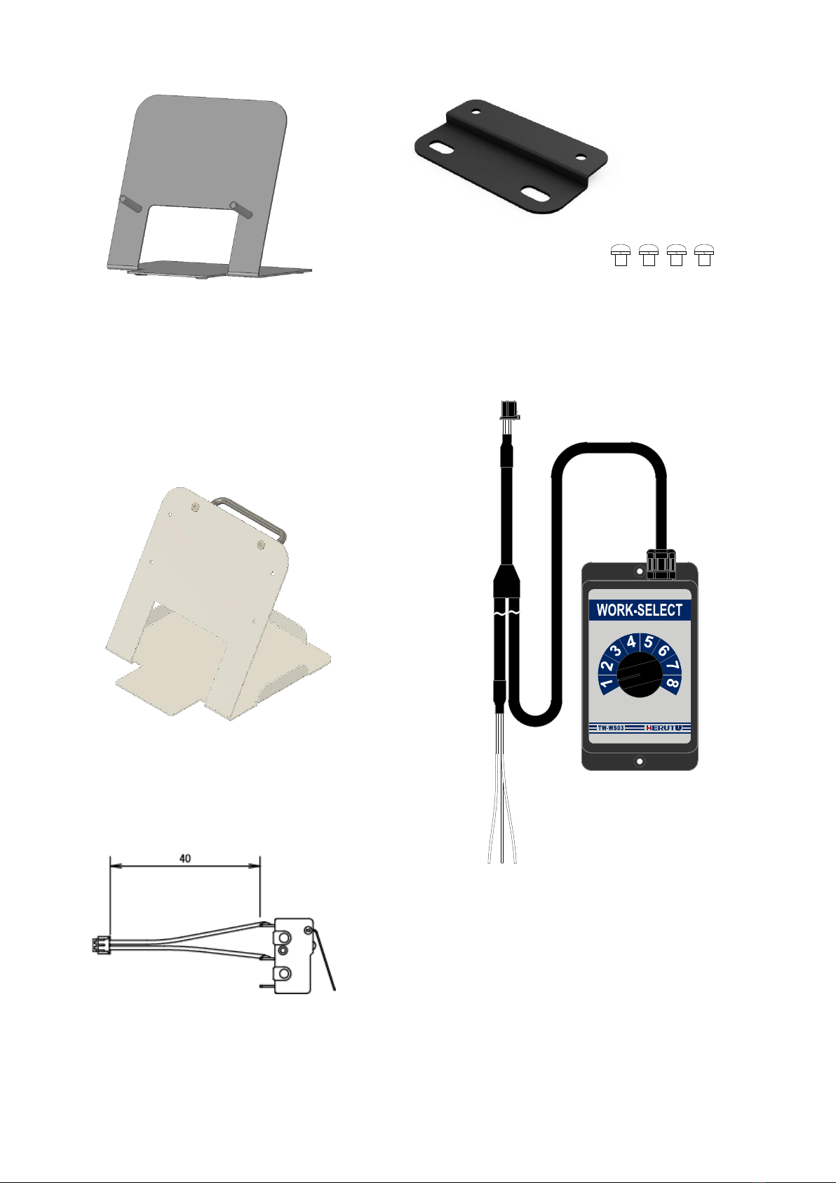
・Desktop Stand TW-SCDS01 ・TW-800R-SCL Wall mounting bracket TW-SCLF01
・Mobile Stand TW-MCLDS01 ・Work-Select Box TW-WS03(Cable 1.7m (5.6ft))
The receiver can be fixed on the stand. TW-800R-MCL
can be connected to Makita’s USB adapter and lithium-ion
battery. The stand comes with a handle that makes it
easy to carry.
・Harness connector with limit switch TW-800T-HCL
(Please purchase 10pcs/ lot.)
Mounting screw M3 × L5 ×4pcs
TW-SCLF01 ×2

5
■3.Safety Precautions (Be Sure to Read This)
This section describes the matters to be observed in order to prevent harm to the users and other persons
and damages to the property.
■The following marks and displays classify and describe the extent of harm and damage caused by failing
to observe the display content and using this product wrongly.
This display column shows "a failure to do observe it could result in only the
personal injury or property damage".
■Handling this product
●This product is the wireless communication equipment made of precision parts. Do not
disassemble or modify it. Or the accident or fault may occur.
■Use and storage environment
●DO NOT USE OR STORE the product in the following places to prevent defects, malfunction,
deterioration, fire, and electric shock:
・Do not use and store it in places exposed to direct sunlight,
・Do not use and store it in places where liquids, foreign substances, corrosive gases or
combustible gases can enter the product,
・Do not use and store it in places with high humidity or where there is abundant oil smoke,
dust, sand, etc. ,
・Do not use it in an unstable place such as a wobbling table or an inclined plane,
・Do not use it in a place with vibration.
■Specific handling of this product
This product is a radio equipment with certification of construction design.
●It is prohibited by law to disassemble or modify certified devices.
●Do not remove the certification label affixed to the case. It is prohibited to use any product
without the label.
●This product is only available in the countries where the certification is acquired.
This display column shows "a failure to do observe it could result in death or
serious personal injury".
■Handling this product
●Do not use this product for application that requires the extremely high reliability affecting the
human life.
●Do not use this product in the area which the radio wave reaches or not.
! Warning
! Caution
6
■Handling the AC adapter
Be sure to observe the followings in order to prevent the accidents such as heat generation, damage, or
ignition of AC adapter.
●Do not place the AC adapter close to fire or insert them into fire. Or they may be burst and
ignited, resulting in the accident.
●Use the AC adapter and main body only at the specified power supply voltage in order to
prevent burst and ignition accidents.
●Do not use main body at the location where they easily get wet. Or the accidents including heat
generation, ignition, or electric shock and faults may occur.
●Do not touch main body, power cord, and power supply terminal base with wet hands. Or the
accident such as an electric shock may occur.
●Do not damage the power cord of the AC adapter. Short-circuit or heat generation may cause
fire or electric shock.
●Do not use the power supply terminal base with dusts attached. Short-circuit or heat
generation may cause fire or electric shock.
●Do not give a strong shock to the AC adapter.
Or the accident or fault may occur.
●If you find a deformation in the AC adapter, do not use it.
Or the accident or fault may occur.
●Do not charge the main body at the location where the flammable gas is generated.
Or the ignition accident may occur.
●Never disassemble main body. Or the accident or fault may occur.
■If a problem occurs during use
Remove the power plug from the outlet because it may cause fire and electric shock. Request the dealer
or our company to repair it.
●When smoke comes or there is a strange smell, immediately stop usage and remove the
power plug from the outlet because it may cause fire and electric shock. Request the dealer or
our company to repair it.
●Do not use this product when its AC adapter cable or the power switch of the main unit is
damaged.
Using the cord damaged continuously may cause fire or electric shock.

7
■Notes on the Radio Law
〇The wireless device used for this product is certified as a specific radio device for a radio equipment of a low power
data communication system based on the Radio Law. Therefore, a radio station license is not required to use this
product.
〇This product can be used only in Japan or countries where required certification is acquired. In the case that it is
used in other countries, this product may be damaged or it may damage other equipment. It also may conflict with the
laws of that country. Please contact our sales department for the countries that the product is certified other than Japan.
〇Do not use this product near any person using cardiac pacemaker. The cardiac pacemaker may be disturbed by
electromagnetic wave, which may cause risk of life.
〇Do not use this product near any medical equipment. The medical equipment may be disturbed by electromagnetic
wave, which may cause risk of life.
〇Do not use this product near any microwave oven. Electromagnetic wave from microwave oven may disturb radio
communication.
〇The wireless device of this product is certified under the Radio Law, so that DO NOT disassemble or remodel this
product.
■Notes on radio interference of 2.4 GHz radio
When communicating with 2.4 GHz band wireless products, pay attention to the following points.
In this product’s frequency band not only industrial, scientific and medical equipment such as microwave ovens but also
local radio stations for mobile objects identification (which require the license), specified low-power radio stations
(license not required), and amateur radio stations (license required) can be in operation.
〇Before using this product, make sure that there are no local radio stations for mobile objects identification, specified
low-power radio stations and amateur radio stations operating nearby.
〇In event that harmful interference occurs to any radio station by the radio wave from this product, stop using it
immediately and consult with us about avoiding interference.
〇Also contact us in case of any trouble such as harmful radio interference to specified low-power radio stations for
mobile objects identification or amateur radio stations.
TW-800R-SCL is equipped with the built-in wireless module HRF-2402.
HRF-2402 Certified Countries : Japan, Canada, USA, China, Thailand, Vietnam, Philippines and India.
■FCC/IC Warning
Information about FCC Standard. (TW-800T, TW-800R-SCL, TW-800R-MCL Common)
FCC CAUTION
Change or modifications not expressly approved by the party responsible for compliance could void the
user’s authority to operate the equipment.
(TW-800T)
This device complies with Part 15 of the FCC Rules. Operation is subject to the following two conditions:
(1) This device may not cause harmful interface, and (2) This device must accept any interface
received, including interface that may cause undesired operation:
(TW-800R-SCL, TW-800R-MCL)
This transmitter must not be co-located or operated in conjunction with any other antenna or transmitter.
(TW-800R-SCL, TW-800R-MCL)
This equipment complies with FCC radiation exposure limits set forth for an uncontrolled environment
and meets the FCC radio frequency (RF) Exposure Guidelines. This equipment has very low levels of
RF energy that is deemed to comply without maximum permissive exposure evaluation (MPE).
(TW-800R-SCL, TW-800R-MCL)
This equipment complies with FCC radiation exposure limits set forth for an uncontrolled environment
and meets the FCC radio frequency (RF) Exposure Guidelines. This equipment has very low levels of
RF energy that is deemed to comply without testing of specific absorption rate(SAR).

8
IInformation about ISED Standard. (TW-800T, TW-800R-SCL, TW-800R-MCL Common)
This device complies with Industry Canada’s applicable license-exempt RSSs. Operation is subject to
the following two conditions:
(1) This device may not cause interference; and
(2) This device must accept any interference, including interference that may cause undesired operation
of the device.
Le présent appareil est conforme aux CNR d’Industrie Canada applicables aux appareils radio exempts
de licence. L’exploitation est autorisée aux deux conditions suivantes :
1) l’appareil ne doit pas produire de brouillage;
2) l’utilisateur de l’appareil doit accepter tout brouillage radioélectrique subi, même si le brouillage est
susceptible d’en compromettre le fonctionnement.
(TW-800R-SCL, TW-800R-MCL)
This equipment complies with IC radiation exposure limits set forth for an uncontrolled environment and
meets RSS-102 of the IC radio frequency (RF) Exposure rules. This equipment has very low levels of
RF energy that is deemed to comply without maximum permissive exposure evaluation (MPE).
Cet équipement est conforme aux limites d’exposition aux rayonnements énoncées pour un
environnement non contrôlé et respecte les règles d’exposition aux fréquences radioélectriques (RF)
CNR-102 de l’IC. Cet équipement émet une énergie RF très faible qui est considérée comme conforme
sans évaluation de l’exposition maximale autorisée (MPE).
(TW-800R-SCL, TW-800R-MCL)
This equipment complies with IC radiation exposure limits set forth for an uncontrolled environment and
meets RSS-102 of the IC radio frequency (RF) Exposure rules. This equipment has very low levels of
RF energy that is deemed to comply without testing of specific absorption rate (SAR).
Cet équipement est conforme aux limites d’exposition aux rayonnements énoncées pour un
environnement non contrôlé et respecte les règles d’exposition aux fréquences radioélectriques (RF)
CNR-102 de l’IC. Cet équipement émet une énergie RF très faible qui est considérée comme conforme
sans évaluation du débit d’absorption spécifique (DAS).
(TW-800R-SCL, TW-800R-MCL)
This radio transmitter (10608A-HRF2402) identify the device by certification number or model number if
Category II) has been approved by Industry Canada to operate with the antenna types listed below with
the maximum permissible gain indicated. Antenna types not included in this list, having a gain greater
than the maximum gain indicated for that type, are strictly prohibited for use with this device.
Antenna type:1/4λ Dipole antenna (chip antenna) Gain: 3dBi
Antenna type:1/2λ Dipole antenna Gain: 2dBi
Antenna type:1/2λ Dipole antenna Magnet Base Gain: 2dBi
Le présent émetteur radio (10608A-HRF2402) a été approuvé par Industrie Canada pour fonctionner
avec les types d'antenne énumérés ci‑dessous et ayant un gain admissible maximal. Les types
d'antenne non inclus dans cette liste, et dont le gain est supérieur au gain maximal indiqué, sont
strictement interdits pour l'exploitation de l'émetteur.
Type d’antenne:1/4λ Dipole antenna (chip antenna) Gain: 3dBi
Type d’antenne:1/2λ Dipole antenna Gain: 2dBi
Type d’antenne:1/2λ Dipole antenna Magnet Base Gain: 2dBi
■Thailand Radio Law (SDoC)
This telecommunication equipment is in compliance with NBTC requirements.
9
■4.Name of Each Part
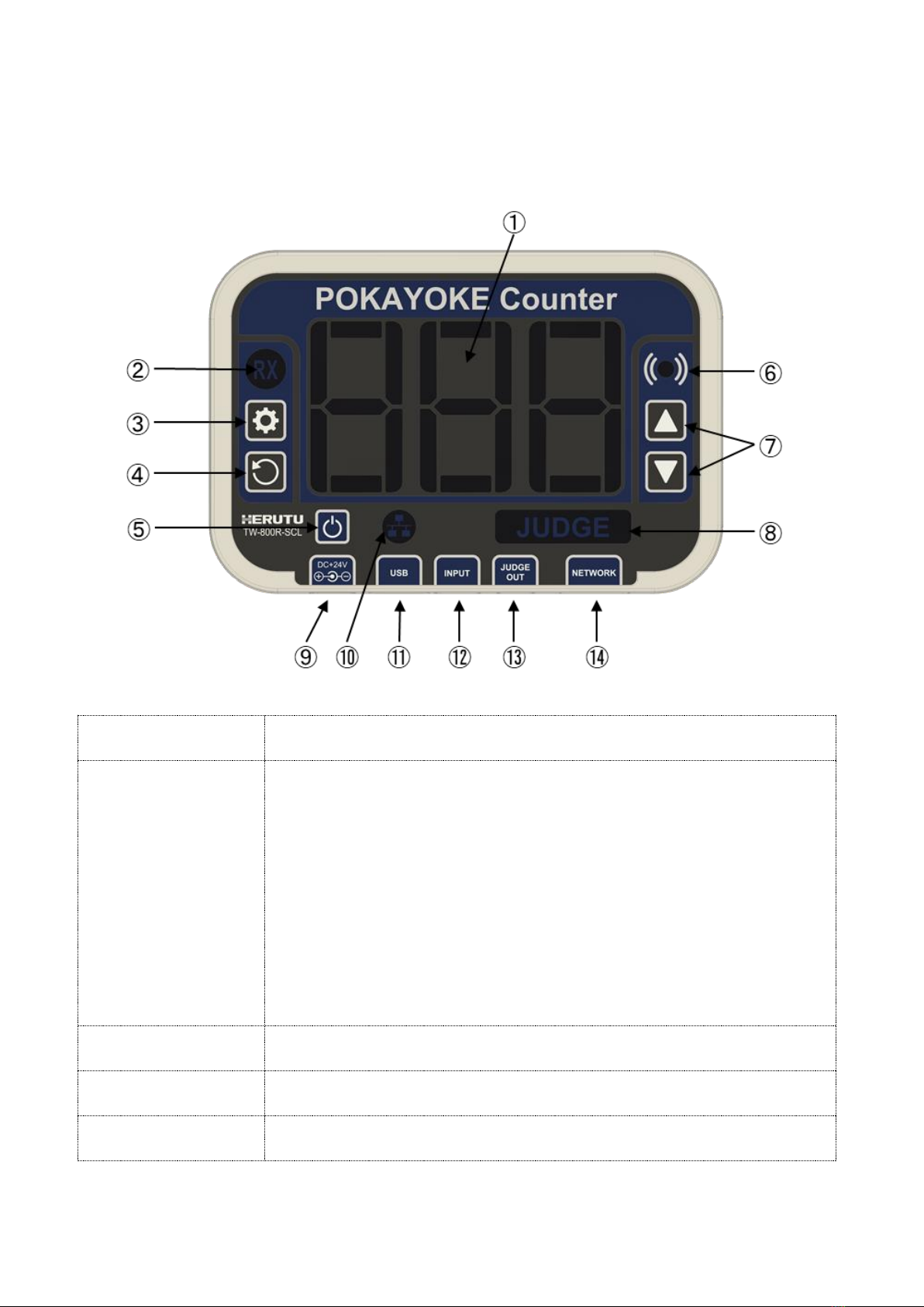
4-1.Receiver
The explanation of TW-800R-SCL is as follows. Please note that the power supply jack (⑨in the figure below)
of TW-800R-SCL and TW-800R-MCL are different in specifications.
①7SEG-LED display
(3-digit)
7SEG-LED displays the count value and various setting values.
②Receiver (RX) LED
The LED lights green when the receiver receives the signal from the
transmitter.
The display varies depending on each mode.
・Lit in green: pairing mode
・Lit in red: when setting the count value.
・Lit in blue: when setting the reset time.
・Lit in yellow: when setting over-count to Valid/Invalid.
・Lit in light blue: when setting the work timer in seconds.
・Blinking in red: when setting count-down or count-up.
・Lit in white: when setting the buzzer volume.
・Blinking in white: when setting the operating mode.
・Blinking in white: In Backup or Restore mode.(JUDGE LED also blinking in
white.)
③Setting (REG) key
The key is used to set Count value, Reset time, Over-count value, Work
timer, Countdown/Count-up, and Buzzer volume.
④RESET key
The key resets the count value, count setting and status such as FAIL
judgment.
⑤POWER key
Power ON → Press the POWER key for 0.1 seconds or more.
Power OFF → Press the POWER key for 2 seconds or more.

10
⑥Buzzer
The buzzer sounds according to each state.
・When receiving a signal from the transmitter: “ping” (1 time 100ms)
・PASS: Sounds Pi pi pi (3 step melody sound)
・FAIL occurs: Sounds Pi-Pi-Pi-…
・(Applicable Only to the “application interlock mode”) When receiving a signal
from the transmitter while not being in communication with POKAYOKE plus:
Same tone as when FAIL occurs.
・When the network setups are changed: Same tone as when FAIL occurs.
⑦Setting (UP/DOWN)
keys
Used in the setting change mode. The key cannot be operated in the count
mode.
Used to set Count value, Reset time, Over-count value, Work timer,
Countdown/Count-up, Buzzer volume and Operating mode.
⑧JUDGE LED
The LED color changes according to the type of Judge.
・Lit in white: Task in progress
・Lit in blue: Task is completed (when judged as PASS)
・Lit in red: FAIL occurred.
・Lit in green: (Applicable Only to the “application interlock mode”) Work is
completed using POKAYOKE plus. (when judged as PASS)
・Lit in yellow: In “simple count mode”.
・Blinking in white: In Backup or Restore mode.
⑨Power jack
Supplies operating power.
・TW-800R-SCL:Connect the included AC adapter.
・TW-800R-MCL:Connect the included power cable.
⑩Network monitor
Indicates the connection status with POKAYOKE plus by lighting or blinking
when the receiver is set to the “application interlock mode”.
・Blue (lit): Communicating with POKAYOKE plus
・Blue (blinking): Communication with POKAYOKE plus is disconnected
Set in “stand-alone mode”and to “simple count mode”, and indicates the
connection status between the devices when the LAN output setting
(Transmitter data ethernet output or Receiver data ethernet output) is
enabled.
・Blue (lit): Communicating with the connected devices.
・Blue (blinking): Communication is disconnected.
⑪USB connector
・Used to update the software with a USB memory stick.
・Used to back up or restore the parameters of the devices with a USB
memory.
⑫External input
Connector for Work-select input, Judge input and Reset input.
Work-select input: Selects a registered work.
Judge input: Judges the task.
Sensor input: Enables the count only when it is “ON”.
Reset input: Returns to the count before the task started.
Use the optional input cable.
⑬Judge output
Connector for Judge output.
Use the optional output cable for Judge output.
⑭LAN cable connector
For LAN output, setting on the Web server, using with POKAYOKE plus, or
linking with an external device, connect the LAN cable.

11
4-2.Transmitter
●TW-800T
①Mounting bracket
Mounting bracket for mounting on the torque wrench.
②Mounting brackets/
Mounting holes
The hole is for mounting the base of torque wrench of LS type and seat.
③Body case
The case is constructed from a durable material: polypropylene.
④LED (Red/ Green)
LED is for confirmation of communication and battery checking. Depend on
the situation, LED is lighting and flashing.
⑤Test switch
(Pairing switch)
For Test switch and paring switch.
⑥Body mounting
screw
The screw is for mounting main body and mounting bracket.
⑦Limit switch
Limit switch is for input the signal from torque wrench.
It is fixed the mount base of torque wrench by hexagon screw.
⑧Battery
Battery is coin battery. Type is CR2032
①
⑦
②
③
④
⑤
⑥
⑧

12
■5.Installation
5-1.Transmitter
Transmitter is used by attaching to various kinds of tools such as torque wrench, plier wrench, check pen, battery
tool etc. As plier wrench and check pen are original products of Herutu Electronics, basically it is shipped with
transmitter attached.
The torque wrench can be attached to the following manufacturer's products.
TOHNICHI Mfg. Co., Ltd.:LS type(QLLS, QSPLS, etc.)
Nakamura Mfg. Co., Ltd.:MBtype(N-SPK-MB, N-QSPK-MB, etc.)
For other tools installation please contact sales department.
<Installation the transmitter to torque wrench>
①To install the seat
Fix the Seat with four fixing screws.
For the application with heavy oil mist, fill up the caulking agent between Wrench seat and Seat and also
betweenWrench shaft and Wrench seat to protect the internal board.
②Fix the Transmitter Limit SW with two hexagon socket head bolts(which was removed).
Verify that the moving range of wrench lever is well suited for the movement range of switch during the wrench
in movement.
The hexagon socket head bolt requires a washer.
Hook the Transmitter on the Case holder of Seat, set it with an attention being paid not to bite the cord, and fix it
with the set screw as firmly pushing the case.
Apply the screw locking agent
onto the 2 to 3 threads of screw
edge.
Apply the screw locking agent on 2 to 3 threads of
hexagon socket head bolt.
Wrench lever
It hooks on a case fixed nail
×4
13
<The attention and the check method on limit switch attachment>
When the lever working range of a torque wrench is small, a limit switch cannot be struck and a transmitter may
not send. In limit switch attachment, be careful enough and carry out.
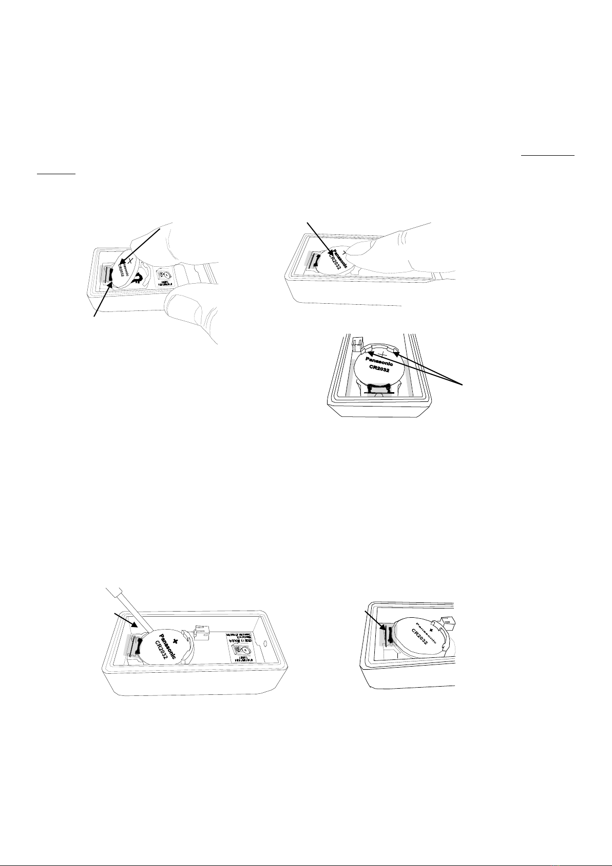
<Installing and removing the battery>
●Installing the battery
First, with the “positive (+) terminal” of the coin battery (CR2032) facing up, insert the battery into the gold plated
terminal of the battery holder, as shown in Fig. 1 below.
Push the battery so that it is secured by two catches in the plastic part of the battery holder until the battery snaps
into place.
●Removing the battery
When removing the coin battery for replacement or other reasons, slide a not sharp-edged object between the
battery and battery holder and gently lift the bottom of the battery, as shown in Fig. 1 below. As shown in Fig. 2
below, the battery can be slid out of the battery holder through the tab of the gold –plated terminal.
Gold plated terminal
①
②
①
②
Two catches in the
plastic part
(Notes!)
Be sure to insert the battery into the gold
plated terminal first. Inserting the battery into
the plastic part first may damage the gold
plated terminal.
The battery is slid out of the holder through the tab of
the gold –plated terminal.
(Notes!)
Care should be taken not to disconnect the limit switch cable of TW-800T while installing or
removing the battery. It is advised to remove the limit switch cable from the connector before
installing or removing the battery.

14
< Replacing the harness connector with limit switch (TW-800T-HCL) >
When replacing the harness connector with limit switch, remove the coin battery and perform the replacement
procedure, as shown below.
①
②
Pull the cable portion near the connector horizontally to let the
connector mating portion come off from the connector.
(Notes)
Remove the cable from the connector carefully. Pulling the
cable up may distort the connector mounted on the substrate
and result in damage to the connector.
Push the white connector portion of a new harness connector
with limit switch using the tip of the fingernail and insert it into
the TW-800T connector. Push in the connector firmly until it
snaps into place. Make sure the direction of the connector is
correct before inserting the connector.
(Notes)
Do not attempt to apply excessive force to the cable when
connecting the connector.

15
5-2.Receiver
1. Install the receiver in a location where it can be seen well from the transmitter and can receive radio waves
stably.
2. Operating power supply is supplied from the power supply jack.
・For TW-800R-SCL, connect it to the includedAC adapter.
・For TW-800R-MCL, use the included power cable to connect the receiver to the USB output power adapter.
As a USB power adapter, Makita Corporation’s USB adapter “ADP05” can be used in combination with an
adaptive lithium- ion battery.
Power supply for TW-800R-MCL
3. Connect the signal to the external input (Work-Select, Judge or Reset) and external output (Judge output), as
necessary.
4. For LAN output, setting on the Web server, using with POKAYOKE plus, or linking with an external device,
connect the LAN cable.
【Notes】
・Please prepare a USB power adapter, Makita’s USB adapter and an adaptive lithium- ion battery. Please refer
to the instruction manuals included in the devices for how to use each device.
・All cables and USB power adapter must be connected or disconnected when the main unit is in the power OFF
state.
・Makita’s USB adapter must be connected or disconnected when the adapter’s power switch is turned OFF.
・Use a USB power adapter with output current of 0.5A or more. If the output current is less than that, the main
unit may not work properly.
・To update the software, use a USB power adapter.
・Do not forcibly pull the power cable connected to the power supply. Doing so may damage the power jack of the
main unit.

16
5-2-1.External output - Judge output (PASS /FAIL)
The external output is an open collector output. When the output turns ON, a short circuit occurs between each
terminal. Be aware that the internal circuit may be damaged when the contact rated load is exceeded.
For use of the Judge output, use the optional output cable for Judge, TW-SCLO-4.
Rated load voltage: DC24V
Rated load current: 0.1A
Contact structure/configuration: Open collector
Connector: Square connector 2.5mm pitch, 2×2 pins, 4 poles(1 pole unused)
No.
Contents
Cable
1
PASS
Red
2
FAIL
Two colors of red and white
3
Unused
―
4
COM
Black
17
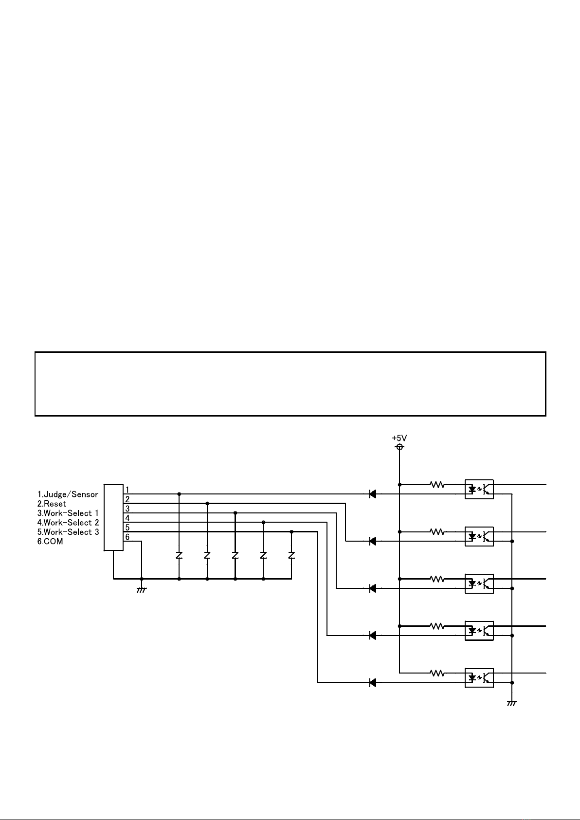
5-2-2.External input - Work-Select input / Judge/Sensor input / Reset input
<Work-Select input>
Up to 8 types of works can be registered by using the Work-Select input. Selects a work according to the type
of task.
<Judge/Sensor input>
Judge input or Sensor input can be set with the Web server function.
・Judge input setting
When the number of tasks equal to the specified count are completed at the timing of the signal input, the
task is judged as PASS and a PASS output is generated. When the remaining counts are found, the task is
judged as FAIL and a FAIL output is generated.
・Sensor input setting
The counter counts only when the signal input is ON. When the signal input is OFF, the counter value blinks.
The receiver does not count nor generate LAN output even after receiving a fastening signal.
set input>
Resets the work at the timing of the signal input. The counter returns to the value before the task started.
The input type is a non-voltage contact input. Connect the input signal to the low chattering switch for turning
ON/OFF DC5V/10mA stably or PLC.
When using the external input, use the optional input cable for Work-Select, Judge and Reset, TW-SCLI-6.
Non-voltage Contact-inputs: Judge/Sensor 1Bit / Reset 1Bit / Work-Select 3Bit / COM
(Photo coupler input)
Contact rating: DC5V/10mA or more
Connector: Square connector 2.5mm pitch, 3×2 pins, 6 poles
This manual suits for next models
2
Table of contents
Other Herutu Receiver manuals

Herutu
Herutu TW-510R User manual

Herutu
Herutu TW-800R-EXL User manual

Herutu
Herutu WCL-426R User manual

Herutu
Herutu WCL-920R User manual

Herutu
Herutu TW-800R-EXS User manual

Herutu
Herutu TW-800R-EXS User manual

Herutu
Herutu AN426RM II User manual

Herutu
Herutu TW-800R-EXP User manual

Herutu
Herutu TW-800R-SLNX User manual

Herutu
Herutu POKAYOKE TWF-600R User manual


