Herutu WCL-426R User manual

LAN Connection TypeAndon Receiver
WCL-426R
INSTRUCTION MANUAL V1.30
Please use this operation manual correctly on reading well.
Please keep it carefully to be able to read immediately, when required.


Table of Contents
1.Overview..................................................................................................................................... 1
1-1.Introduction ......................................................................................................................... 1
1-2.Main Unit and Accessories ................................................................................................ 1
1-3.Safety Precautions (Be Sure to Read This)...................................................................... 2
1-4.Outline.................................................................................................................................. 4
2.Specification............................................................................................................................... 5
2-1.Radio Part Specification..................................................................................................... 5
2-2.General Specification ......................................................................................................... 5
3.Part Names and Descriptions................................................................................................... 6
4.Drawing....................................................................................................................................... 7
5.Prepare to Start Communication.............................................................................................. 8
5-1.Installation of "Device Installer"........................................................................................ 8
5-2.Factory Default IP Address................................................................................................ 8
5-3.IP Address Settings and Procedure.................................................................................. 8
6.Settings..................................................................................................................................... 15
7. Communication Command Function..................................................................................... 17
7-1.Information Acquisition Command................................................................................. 17
7-2.Setting Command ............................................................................................................. 17
7-3.Command Execution Result............................................................................................ 17
8.Installation Procedure............................................................................................................. 21
8-1.Receiver Installation......................................................................................................... 21
8-2.LAN connector .................................................................................................................. 22
9.Description of Operation......................................................................................................... 23
9-1.Basic Operation................................................................................................................. 23
9-1-1.Opening....................................................................................................................... 23
9-1-2.Receive Data from Transmitter................................................................................. 23
9-2.LED Monitor....................................................................................................................... 24
9-3.Processing at Power ON.................................................................................................. 26
10. After Service and Warranty ................................................................................................... 27

1
1.Overview
1-1.Introduction
This instruction manual describes the information required for using this product including overview,
installation, and operation of this product. Read this manual carefully before using this product. Keep this
manual handy so that you can take it out immediately.
▪Do not use this product for the application that may cause harm to human body or damage to other
devices and equipment.
Do not use this product near the devices that may malfunction due to radio waves emitted from this
product.
▪Because the communication performance is changed depending on the surrounding environment, be
sure to confirm the communication is established before installation of this product and then use it.
1-2.Main Unit and Accessories
■Receiver
Receiver main unit “WCL-426R”×1
AC adapter “ADB24050” x1
Cable Approx. 1.5 m
Antenna “TK-1842”×1
2
1-3.Safety Precautions (Be Sure to Read This)
This section describes the matters to be observed in order to prevent harm to the users and other persons
and damages to the property.
■The following marks and displays classify and describe the extent of harm and damage caused by failing
to observe the display content and using this product wrongly.
This display column shows "a failure to do observe it could result in death or
serious personal injury".
This display column shows "a failure to do observe it could result in only the
personal injury or property damage".
■Common matters in handling
●Avoid using this product in the humid or dusty place. Dusts or water enters the product,
which may cause the fault, fire, or electric shock.
■Handling this product
●This product is the wireless communication equipment made of precision parts. Do not
disassemble or modify it. Or the accident or fault may occur.
■Handling this product
●Do not use this product for application that requires the extremely high reliability affecting
the human life.
●Do not use this product in the area which the radio wave reaches or not.
■Handling the power supply
Be sure to observe the followings in order to prevent the accidents such as heat generation, damage, or
ignition ofAC adapter and power cord.
●Do not place the AC adapter and power cord close to fire or insert them into fire. Or they
may be burst and ignited, resulting in the accident.
●Use the AC adapter and main body only at the specified power supply voltage in order to
prevent burst and ignition accidents.
! Warning
! Caution
! Caution
! Warning

3
●Do not use the AC adapter and main body at the location where they easily get wet. Or the
accidents including heat generation, ignition, or electric shock and faults may occur.
●Do not touch the AC adapter, main body, power cord, and outlet with wet hands. Or the
accident such as an electric shock may occur.
●Do not damage the power cord. Short-circuit or heat generation may cause fire or electric
shock.
●Do not use the power plug with dusts attached. Short-circuit or heat generation may cause
fire or electric shock.
●Do not give a strong shock to theAC adapter.
Or the accident or fault may occur.
●If you find a deformation in theAC adapter, do not use it.
Or the accident or fault may occur.
●Do not charge the main body at the location where the flammable gas is generated.
Or the ignition accident may occur.
●Never disassemble the AC adapter.
Or the accident or fault may occur.
■Never disassemble the AC adapter.
Remove the power plug from the outlet because it may cause fire and electric shock. Request the dealer
or our company to repair it.
●When smoke comes or there is a strange smell, immediately stop usage and remove the
power plug from the outlet because it may cause fire and electric shock. Request the dealer
or our company to repair it.
●If the cord is damaged, do not use it. Using the cord damaged continuously may cause fire
or electric shock.
■Reliability of wireless communication
As wireless communication has properties that are different from those of wired communication,
communication errors may occur due to the following.
・Exceeds the communication distance.
・Enters a dead zone.
・Interfered by strong jamming
If signals are often jammed, or being jammed leads to operational problems, stop using the systems and
restart using the systems after removal of the cause.
Radio waves may not be received due to various reasons other than the above. Please understand this
before using the systems.
* A dead zone is an area where the radio wave transmitted from the transmitter becomes extremely weak
due to radio waves reflected from walls or other objects.

4
1-4.Outline
WCL-426R is a LAN connection typeAndon*1 receiver (hereinafter called “receiver”).
The receiver can wirelessly receive in real-time trouble occurrence reports transmitted from theAN426TⅡ
transmitter installed at the workstations and machines of the production line.
In addition, the receiver can externally output the received reports of trouble occurrence via LAN.
By utilizing and analyzing the information of trouble occurrences on the production line with applications on
computers, tablets and in the cloud, the receiver can be useful for visualizing and improving the operation
status of the production line.
Using the Windows application “Production Process Support Software for WCL Series WCL plus,” you can
save the trouble occurrence history received by up to 10Andon receivers in the CSV format.
1. At the transmitter, there are two selectable input methods for reporting trouble occurrences: one for
workers with four push-buttons (orange, red, green, and white) and one for machines with four external
inputs (orange, red, green, and white).According to possible trouble occurrences in the production line,
you can assign each color a meaning, such as red for an exception occurrence, orange for parts out of
stock, green for requesting transportation of finished products, or white for trouble solved.
2. When using the receiver linked to a wireless Andon seriesAN426Ⅱ, one receiver can wirelessly
communicate with up to 800 transmitters and a maximum of 10 receivers can be used in a factory. This
enables trouble occurrence reports to be collected from up to 8,000 locations in a factory.
When using the receiver with the transmitter without linking to a wirelessAndon seriesAN426Ⅱ, each
receiver can wirelessly communicate with up to 1,000 transmitters and a maximum of 10 receivers can
be used within a factory. This enables trouble occurrence reports to be collected from up to 10,000
locations in a factory.
*1:A system to notify management, maintenance, and other workers of a quality or process problem.

5
2.Specification
2-1.Radio Part Specification
Item
Specification
Frequency Band
426.0250MHz~426.1375MHz
Modulation Band
Direct 2-value FSK modulation
Modulation Speed
Approx.977bps
Channel Step
12.5kHz(Step 10Wave)
Antenna
External Whip Antenna
Communication
Method
Receive only
2-2.General Specification
Item
Specification
Interface
Ethernet IEEEE802.3 10Base-T/100Base-TX Auto switching
Connector: RJ-45 ×1
Indication for network 2-color LED ×2
Display
Red LED × 1 (Power supply monitor)
Red/Green 2-color LED × 1 (Monitor for wireless communication)
Red/Green 2-color LED × 1 (Monitor for wired communication)
Power Source
DC24V (Available at AC100-240V with supplied AC adapter.)
Current Consumption
Approx. 120mA
Operating
Environment
Temperature:0-+40℃(32-104°F)
Humidity:35-80% (without condensation)
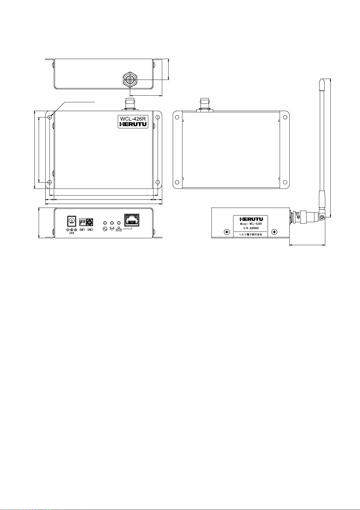
External Dimensions
(W × H × D) 135 × 90 × 35mm (5.3 × 3.5 × 1.4″) (excluding protrusions)
Weight
Approx. 380g (13.4 oz)
Switches
2P DIP switch × 1 (For normal operation settings)
16P rotary switch × 1 (For channel settings)
Accessory
1 AC adapter, 1 Antenna

6
Setting switch
Connector for antenna
LED monitor
LAN Connector
DC jack
Mounting hole
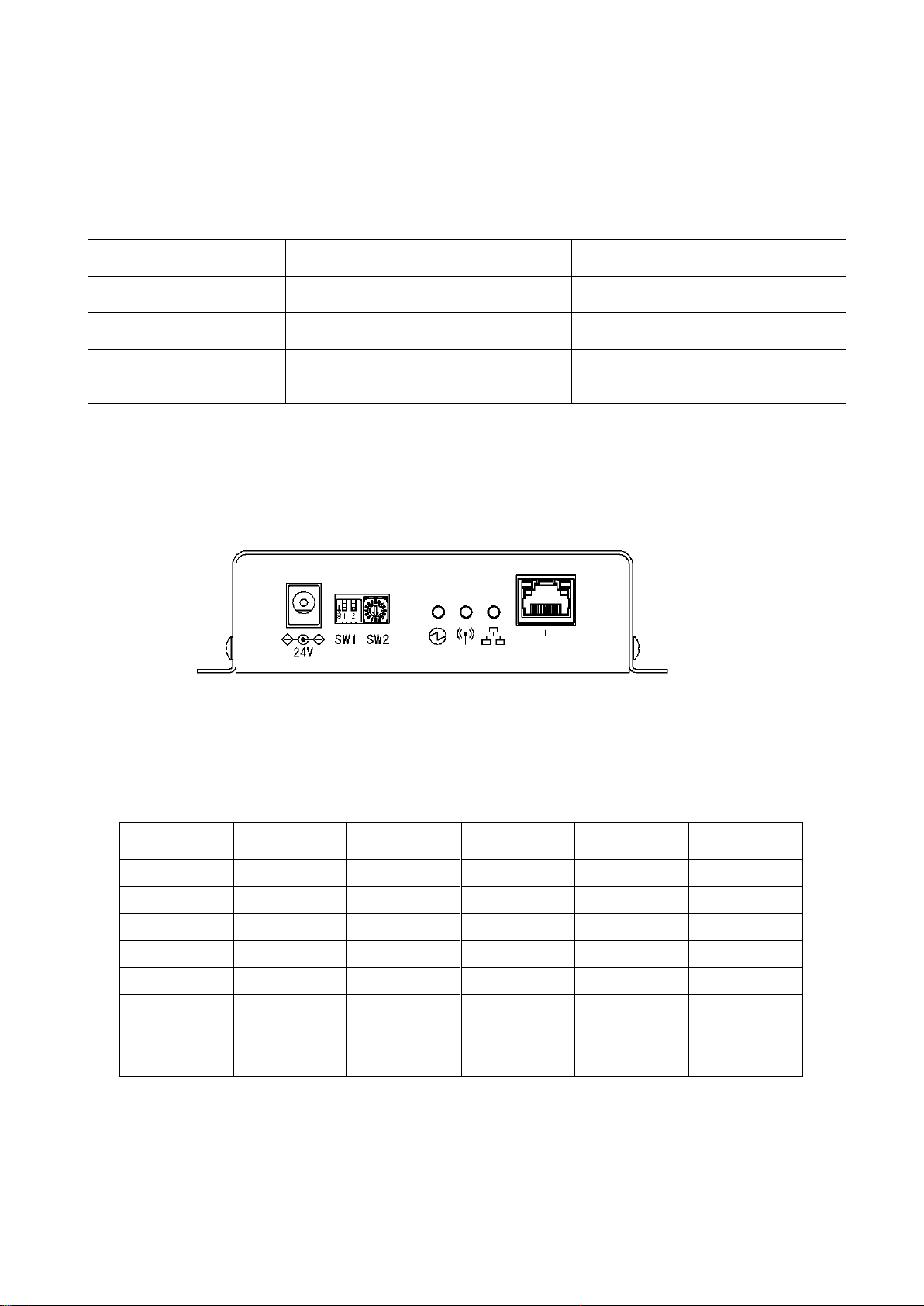
3.Part Names and Descriptions
Name
Function
Connector for
antenna
Connector for connection to the antenna. (BNC-J Connector)
Attach the supplied antenna.
Mounting holes
Mounting hole of φ4.5 × 4
DC jack
DC jack for connection of the included AC adapter.
Setting switch
DIP switch and rotary switch for settings.
LED monitor
LEDs for power supply, wireless communication and wired communication.
LANConnector
Connector for LAN connection. (RJ-45)
7
24
37
90
75
4-φ4.5取付穴
125
115
135
10 10
35
(41)
(160)
4.Drawing
4-φ4.5 Mounting hole

8
Link LED
Activity LED
RJ-45
- Fig. 1 Screen to start Device Installer -
5.Prepare to Start Communication
Before use of the receiver, set each receiver according to the use environment.
Set the IP address and other required items of the receiver by using Lantronix’s Windows-based software,
“Device Installer”.
5-1.Installation of "Device Installer"
Download “Device Installer” from Lantronix’s WEB site (https://www.lantronix.com/products/deviceinstaller/)
to install it on your PC.
Connect the receiver to the HUB capable of communicating with the PC on which “Device Installer” is
installed.
CAUTION
To connect the receiver to the PC with “Device Installer” installed using a LAN cable, be sure to
use a cross LAN cable.
Check the left LED on the LAN connector (RJ-45) of the receiver to see if the Link LED is ON.
When connected to 10Base-T, the Link LED lights up in orange. When connected to 100Base-TX, the Link
LED lights up in green.
If the Link LED is not ON, the receiver cannot communicate with the network. Confirm if the LAN cable and
HUB are correctly connected.
5-2.Factory Default IP Address
The factory default IP address of the receiver is as follows:
IPAddress 192.168.3.100
Subnet Mask 255.255.255.0
Default Gateway 0.0.0.0
Port No. 50001
5-3.IP Address Settings and Procedure
Check that the power of the receiver is ON and that the receiver is properly connected to the HUB or PC,
and then start “Device Installer” from the start menu.
The connected receiver is displayed on the main window (Fig.1).
IP address of the receiver connected to the LAN
IP address

9
- Fig. 2 Select IP address of Xport to change -
- Fig. 3 IP address assignment -
To change the IP address, select the address of the X port on the left of the screen.
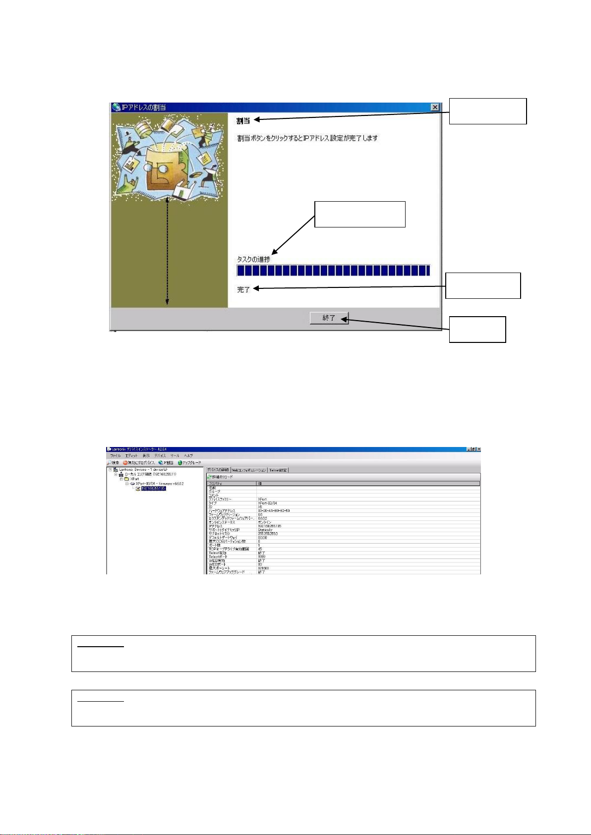
Click “IP assignment button”, and the screen is displayed as shown in Fig.3. Select to assign an IP address
automatically or specify an IP address directly. This document explains about specifying an IP address.
Check “Assign a specific IP address” and click the “Next” button.
IP assignment button
Select IP address to change
IP address assignment method
Automatic IP address acquisition
Allocation of specific IP address
Device details
Next

10
- Fig. 4 IP address input screen -
- Fig. 5 Assignment input screen -
Enter the IP address, subnet mask and default gateway.
*Before setting an IP address, obtain permission from the network administrator.
Click “Next” button.
Click “Assignment” button.
IP settings
IP address
Subnet mask
Default gateway
Next
Assignment
11
- Fig. 6 Input end screen -
- Fig. 7 IP address display screen after change -
When the setting is completed, the “Exit” button becomes active.
It may take some time before the setting is completed. Please wait until the setting is completed.
Click the “Exit” button, and the screen is displayed as shown in Fig.7. Confirm if the IP address has changed
properly.
CAUTION
If the IP address set by the customer is already used on the network, the signals will run into each
other. Set another IP address.
CAUTION
This product is intended to be used on a closed network that is not connected to the internet. Do
not use this product in an open network environment that is connected to the internet.
Assignment
Task progress
Completed
Finish

12
Navigate button
- Fig. 8 WEB configuration setting screen -
- Fig. 9 Password input screen -
■Change Password
The WEB screen (Web Manager) inside X port requires user authentication by password.
Change the default password in the following procedure.
CAUTION
Leaving the default password can cause a security risk to the product. Be sure to change the
default password.
Click the “WEB configuration” tab on the screen in Fig.7, and the screen in Fig.8 is displayed.
Click the “Navigate” button and the password entry screen in Fig.9 is displayed.
Please leave the user name blank.
Enter the following password. When the entry is completed, click the “OK” button.
Initial password NuM7?FrC@nVT8Z1Q
Web Configuration
User name
Password

13
“Server” button.
- Fig. 10 Web Manager initial screen -
On the “Web Manager” screen in Fig.10, click the “Server” button.

14
- Fig. 11 Server settings initial screen -
Click the “Server” button, and the “Server Settings” screen in Fig.11 is displayed.
①Set the “Enhanced Password” radio button to “Enable”.
②Enter a new password (up to 16 characters) in the “Telnet/Web Manager Password” field.
③Enter the same password as ②in the “Retype Password” field.
④Click "OK" button. If the passwords entered in ②and ③match, "Done!" will be displayed to the right of
the "OK" button. If the passwords entered in ②and ③are different, an error message "Passwords do
not match. Please retry again." is displayed. Retry ②and ③again.
⑤Click "Apply Settings" button.
When the process is completed, the password entry screen is displayed. Enter the set password and
press the "OK" button. (Please leave the user name blank.) If login is successful, the settings are
complete. Press the “x” button on the top right of the screen and the application exits.
CAUTION
When reconfirming the changes made to the settings, the changes may not be reflected in the
display. In that case, reboot the software (Device Installer) and check the changes again.
■About settings various parameters
Various parameters can be set on the WEB screen (Web Manager) inside X Port. However, do not change
the settings of the parameters. The default values are set to work properly.
①
②
③
⑤
④
15
6.Settings
Use the rotary switch, DIP switches or Ethernet communication command to set the receiver.
Details of the settings and methods for changing the settings are as follows:
Turn OFF the power of the main unit before changing the settings of the rotary switch or the DIP switch.
Setting contents
Setting by switch
Setting by Ethernet communication
command
Channel settings
〇*1
〇*2
Ethernet communication
command settings
〇
×
Terminal code settings of
Ethernet communication
command
×
〇*2
*1: This setting is available only when the Ethernet communication command is set to “Invalid”.
*2: This setting is available only when the Ethernet communication command is set to “Valid”.
For the setting by the Ethernet communication command, refer to "7. Communication Command Function".
■Channel settings
Set the channel settings according to the transmitter that will communicate with the receiver.
< Channel >
SW2
Channel
Frequency
(MHz)
SW2
Channel
Frequency
(MHz)
1
1
426.0250
9
9
426.1250
2
2
426.0375
A
10
(426.1375)
3
3
426.0500
B
10
(426.1375)
4
4
426.0625
C
10
(426.1375)
5
5
426.0750
D
10
(426.1375)
6
6
426.0875
E
10
(426.1375)
7
7
426.1000
F
10
(426.1375)
8
8
426.1125
0
10
426.1375
*When A to F are set, 0 (channel 10) is set for the channel.

16
■Ethernet communication command settings
Select Valid/Invalid for the Ethernet communication command.
When this setting is “Valid”, the devices are set to the setting of the Ethernet communication command. The
settings are stored until the power is ON next time.
When this setting is “Invalid”, the devices are set to the setting of the rotary switch or the DIP switch.
When this setting is “Invalid”, the receiver returns an error response after receiving the Ethernet
communication command and the command will not be reflected as the setting of the device.
SW1-1
OFF
ON
Ethernet communication
command settings
Invalid
Valid
*SW1-2 is not available.

17
7. Communication Command Function
The Ethernet communication command allows information acquisition and device settings of the receiver to
be changed.
To use the Ethernet communication command function, “Ethernet communication command settings” of the
DIP switch, SW1-1 must be valid.
7-1.Information Acquisition Command
@?Command<Space>[Param]<Terminal code>
1
First code
“@?” Fixed (40H, 3FH)
2
Command
Command for acquiring each information
3
Space
If an argument exists, separate the argument with spaces
(20H).
4
Param (Argument)
If there are multiple arguments, separate them with”,” (2CH).
5
Terminal code
Use one of CR/LF/CRLF.
(Value set by the command for setting the terminal code.
The default value is CRLF.)
7-2.Setting Command
@Command<Space>[Param]< Terminal code >
1
First code
“@?” Fixed (40H)
2
Command
Command for each settings
3
Space
If an argument exists, separate the argument with spaces
(20H).
4
Param (Argument)
If there are multiple arguments, separate them with”,” (2CH).
5
Terminal code
Use one of CR/LF/CRLF.
(Value set by the command for setting the terminal code.
The default value is CRLF.)
7-3.Command Execution Result
<At normal termination>
When the setting command terminates normally, the command execution result is as follows:
<First code>Command<Space>OK<Terminal code>
1
First code
“@?” Fixed (40H)
2
Command
Command for each settings
3
Space
Separate Command and OK with a space (20H).
4
OK (Execution result)
“OK” (4FH,4BH) ASCII string
5
Terminal code
Use one of CR/LF/CRLF.
(Value set by the command for setting the terminal code.
The default value is CRLF.)
Table of contents
Other Herutu Receiver manuals

Herutu
Herutu POKAYOKE TWF-600R User manual

Herutu
Herutu TW-800R-MCL User manual

Herutu
Herutu WCL-920R User manual

Herutu
Herutu TW-800R-EXS User manual

Herutu
Herutu TW-800 Series User manual

Herutu
Herutu AN426RM II User manual

Herutu
Herutu TW-800R-EXS User manual

Herutu
Herutu TW-800R-EXP User manual

Herutu
Herutu TW-510R User manual

Herutu
Herutu TW-800R-EXL User manual


