Herutu TW-800 Series User manual

Wireless Communication
TW-800
Manual V1.20
Please use this operation manual correctly on reading
well. Please keep it carefully to be able to read
immediately, when required.
Contents
■General outline ......................................................1
■Main part and accessories ....................................2
■Safety concerns .....................................................4
■Name and function of each part ...........................8
■Installation............................................................10
■Setting ..................................................................15
■How to use ...........................................................18
■Specification ........................................................20
■Dimensional drawing...........................................22
■After service and Warranty .................................26


TW-800
1
■General outline
TW-800 is constituted by a Transmitter[TW-800T] and a Receiver [TW-800R]
Once the TW-800T is mounted on the Torque wrench a tool of others with Limit switch (LS), the tightening
completion signal of Torque wrench can be transmitted to each series of our TWF-800R.
<Feature>
◆Reliable communication
TW-800 can communicate automatically by selecting the channel from 78ch in 2.4GHz bandwidth.
TW-800 transmits the signal reliably by 2way communication.(You can look see the communication OK/NG by
LED lighting and flashing.)
◆TW-800T has the function of remaining battery level notice.(At using test switch)
If remaining battery level is low at using test switch, you can look see the LED situation of TW-800T and
TW-800R.
◆TW-800T uses CR2032 type of battery for small size and light weight.(Size is same as TW-510T)
◆The case of TW-800T is used polypropylene for protecting broken the case.
◆TW-800 uses the communication band which can be used worldwide.
◆TW-800T has test switch for test communication and battery remaining check.
◆It is easy to set the registry of TW-800T and TW-800R.
It is easy to do ”Pairing”with TW-800T and TW-800R.It is not necessary to manage the channel and ID.
◆TW-800R can be set various setting
1.Buzzer: On/Off
2.Buzzer volume:2 kinds Small/Big
3.Output time of Photo-Mos relay: 4kinds 50ms/200ms/400ms/1s
4.Double-count protect time: 4 kinds 10ms/200ms/1s/2s
◆The power source of TW-800R is DC24V.
The power source of TW-800R that is often connected with controlled equipment is DC24V.
It can be used AC100-240V by using AC adapter of option
※For the cause of transmitter ”TW-800T” and receiver “TW-800R” recognize both sides by pairing, equipment
configuration is set to 1to 1.It can’t be used two or more sets of transmitter for one set receiver.

TW-800
2
■Main part and accessories
Transmitter TW-800T
Receiver TW-800R
Coin battery CR 2032×1 Screw for fitiing M4×L5×4
TW-800T ×1
(Screw for fitting a mainpart, Limit switch)
Fitting plate×1
TW-800R ×1
(Dipole antenna for ANT2 is set at shipment)
※ANT2 is fixed by resin before shipment by regulation of FCC/IC
in an applicable country.

TW-800
3
Onerous option
・AC Adapter ADB24050-C(With connecting cable 3m)
・External antenna MB-13F(With magnet base/Coaxial cable approx 1.5m)
※ANT2 is fixed by resin before shipment by regulation of FCC/IC in an applicable country.
Cable approx 1.5m
Cable approx 2m
Coaxial cable approx 1.5m
Antenna approx 22.5cm

TW-800
4
■Safety concerns
Safety concerns (Be sure to read)
To prevent human injury of user or damage in property from occurring, be sure to observe the precautions
shown below.
■ The degree in safety hazard and damage generated by the wrong usage while ignoring the descriptions is
classified by the following displays.
Using in an improper way while ignoring this pictorial symbol might cause a death or
serious human injury.
Using in an improper way while ignoring this pictorial symbol might cause a human injury
or property damage.
■The type of descriptions you should observe is classified by the following pictorial symbols.
This pictorial symbol indicates a “Reminder” to attract an attention.
This pictorial symbol indicates a “Prohibition” to prohibit a certain action.
■ For the usage to be commonly applied in all the models:
●Avoid using in a place with a plenty of humidity or dust. Otherwise, absorbing a dust or water
contents may cause machine trouble, fire or electrical shock.
■For handling this machine:
●This is the electronic devise or wireless radios composed of the precision parts.
Do not overhaul/remodel. It may cause accident or machine trouble.
■ For handling this machine:
●Do not use this product for the application needing the high reliability related to human lives.
●Do not use this product in a place where it is uncertain about whether or not radio waves reach.
Warning
!
Caution
!
!
!
Warning
!

TW-800
5
■For handling the power source:
Be sure to observe the following precautions to prevent the AC adapter and Power cord from being heated,
damaged, or ignited.
●Do not approximate the AC adapter and Power cord to a fire, or do not put them into a fire. The
AC adapter and Power cord can be broken or ignited, resulting in an accident.
●You can use the AC adapter and main body only with the specified power voltage to protect them
from the damage and fire accident.
●Do not use the AC adapter and main body in a wettable atmosphere. It may cause accidents or
troubles such as heating, igniting or electrical shock.
●Do not touch the AC adapter, main body, Power cord and Plug outlet with wet hands. It may
cause an accident such as electrical shock, etc.
●Do not damage the Power cord. A short-circuit or heating may cause a fire or electrical shock.
●Do not use the Power plug with dust being adhered.
A short-circuit or heating may cause a fire or electrical shock.
●Do not give a strong impact onto the AC adapter. It may cause an accident or machine failure.
●If you find out deformed AC adapter, do not use it.
It may cause an accident or machine failure.
●Do not charge this equipment in a place where flammable gas can be generated.It may cause a
fire accident.
●Never overhaul the AC adapter.
It may cause an accident or machine failure.
■When trouble happens during use:
Since it may cause a fire or electrical shock, disconnect a power plug, and immediately ask outlet store or
our company to repair.
●When smoke or abnormal odors are generated, stop using, immediately disconnect a power
plug, and ask outlet store or our company to repair.
●Once the Power cord is damaged, do not use it.
Using it as is may cause a fire or electrical shock.
!
Warning
!

TW-800
6
■Caution for wireless Law
○Radio device in this product has been certified by the Radio Law. It does not needs a license of radio stations
according to using this product.
○Do not use it close to a person with a cardiac pacemaker.
Electromagnetic interference may affect it, putting his/her life at risk.
○Do not use it close to medical equipment.
Electromagnetic interference may affect the cardiac pacemaker to cause loss of human life.
○Do not use it close to an electric oven.
Electromagnetic interference may affect the medical equipment to cause loss of human life.
○Radio device in this product has been certified by the Radio Law. Do not disassemble or modify this product.
■Caution for Radio Interference with 2.4GHz Wireless communication
Take the following precautions for communication by 2.4GHz wireless communication.
Within this product's frequency range, industrial, scientific, and medical equipment, such as electric oven, as well as
RFID premises radio stations (license required) and specified low power radio station and ham radio station (license
not required) used in factory manufacturing lines are operated.
○Before using this device, confirm that no RFID premises radio station, specified low power radio station,or ham radio
station is operating close to it.
○If this product caused radio interference with an RFID premises radio station, immediately change the product's
frequency or stop radio emission, and contact representative for actions to take to prevent cross talk.

TW-800
7
■FCC/IC Warning (TW-800T,TW-800R)
Information about FCC Standard.
FCC CAUTION
Change or modifications not expressly approved by the party responsible for compliance could void the
user’s authority to operate the equipment.
This device complies with Part 15 of the FCC Rules. Operation is subject to the following two conditions:
(1) This device may not cause harmful interface, and (2) This device must accept any interface
received, including interface that may cause undesired operation:
Information about FCC Standard and IC standard.
This device complies with Part 15 of FCC Rules and Industry Canada licence-exempt RSS standard(s).
Operation is subject to the following two conditions: (1) this device may not cause interference, and (2)
this device must accept any interference, including interference that may cause undesired operation of
the device.
Le présent appareil est conforme aux la partie 15des règles de la FCC et CNR d'Industrie Canada
applicables aux appareils radio exempts de licence. L'exploitation est autorisée aux deux conditions
suivantes : (1) l'appareil ne doit pas produire de brouillage, et (2) l'utilisateur de l'appareil doit accepter
tout brouillage radioélectrique subi, même si le brouillage est susceptible d'en compromettre le
fonctionnement.
Information about SDoC(Thailand)
This telecommunication equipment conforms to technical standard NTC TS 1010-2550.
This telecommunication equipment conforms to NTC technical requirement.
Information about SDPPI(Indonesia)
Transmitter TW-800T Receiver TW-800R
29487/SDPPI/2013
4256
29486/SDPPI/2013
4256

TW-800
8
■Name and function of each part
●Transmitter TW-800T
1.Seat Seat is for setting torque wrench and plier wrench and so on.
2.Hole of bracket The hole is for mounting the base of torque wrench of LS type and seat
3.Case Case for main body. It is used indestructible polypropylene materials.
4.LED(Red/Green) LED is for confirmation of communication and battery checking. Depend on the situation,
LED is lighting and flashing
5.Test switch
(Pairing switch)
For Test switch and paring switch.
6.Screw for fixing The screw is for mounting main body and seat
7.Limit switch Limit switch is for input the signal from torque wrench.
It is fixed the mount base of torque wrench by hexagon screw.
8.Battery Battery is coin battery. Type is CR-2032
1
7
2 3
4
5
6
8
Label is changed for FCC/IC.

TW-800
9
●Receiver TW-800R
1.Power switch For power ON and OFF
2.Terminal block of
power source Terminal block for power source of DC24V(M3)
3.DIP Switch For setting DIP switch(6 selection)
4.Output terminal block Photo-mos relay output terminal block(M3)
5.RX light switch:Green
(for Paring switch)
Led lights at receiving the signal from transmitter normally.
Also RX light switch is used for paring.
6.I/F for Expanding unit At connecting Expand unit, the cover is unfixed.
7.Antenna
2 antennas for Diversity type. Antennas is dipole type.
One is all-in-one, one is possible to take off.
When it is set external antenna, it is set by means of taking off ANT2.
※ANT2 is fixed by resin before shipment by regulation of FCC/IC in an applicable country.
8.Buzzer
Buzzer sounds at receiving the signal from transmitter.
It is possible to set sounds on and off, or big and small.
Sound pressure 95dB/m
9.Led of Power(Red) It lights at power ON.
1
9
2
7
5
4
6
3
8
This label is added
For FCC/IC.
TW-800
10
■Installation
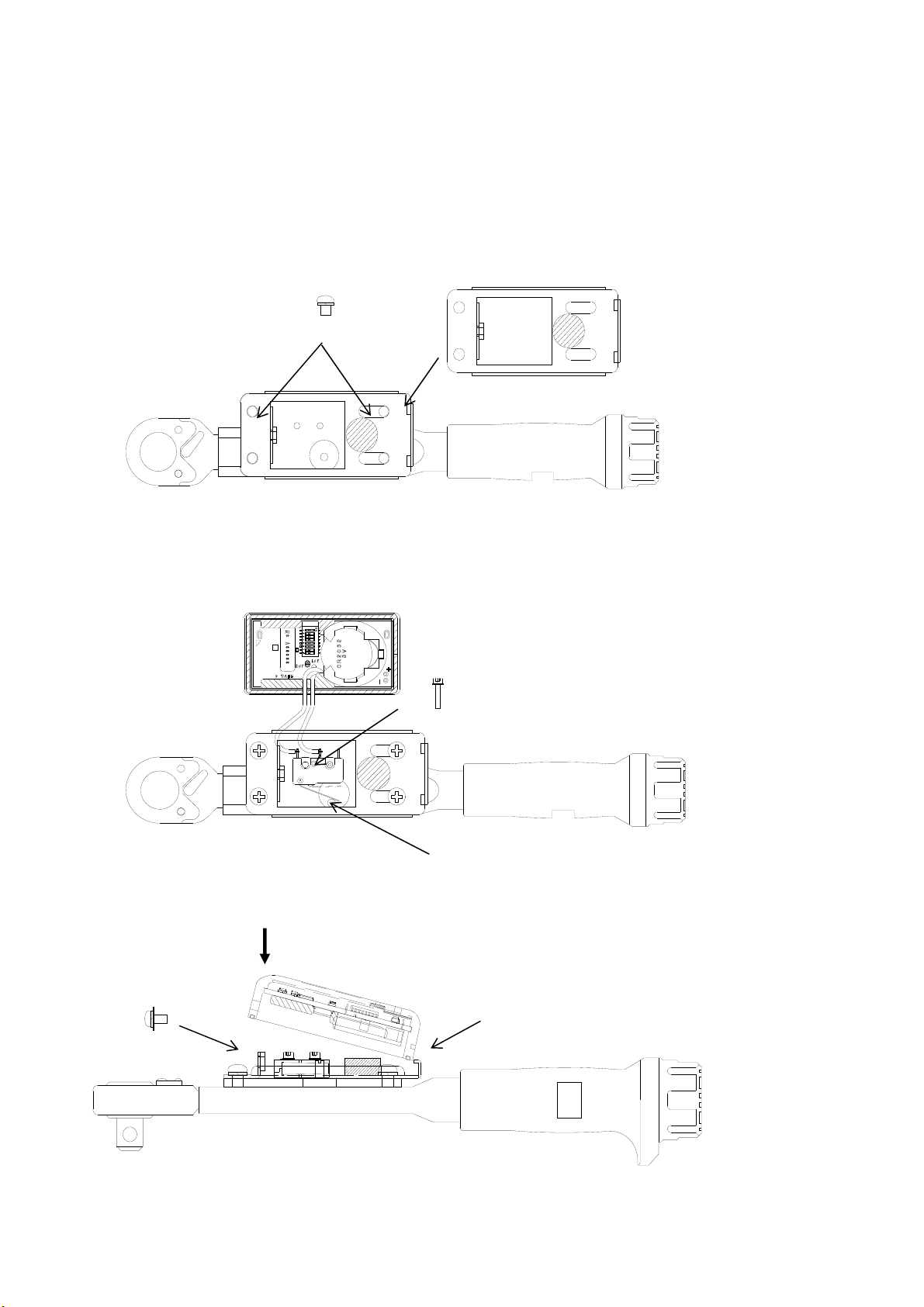
<Installation the transmitter to torque wrench>
To install the seat
Fix the Seat with four fixing screws.
For the application with heavy oil mist, fill up the caulking agent between Wrench seat and Seat and also between
Wrench shaft and Wrench seat to protect the internal board.
Fix the Transmitter Limit SW with two hexagon socket head bolts(which was removed).
Verify that the moving range of wrench lever is well suited for the movement range of switch during the wrench
in movement.
Hook the Transmitter on the Case holder of Seat, set it with an attention being paid not to bite the cord, and fix it
with the set screw as firmly pushing the case.
Apply the screw locking agent on 2 to 3 threads of
hexagon socket head bolt.
Wrench lever
Apply the screw locking agent
onto the 2 to 3 threads of screw
edge.
The hexagon socket head bolt requires a washer.
It hooks on a case fixed nail
×4
×2

TW-800
11
<The attention and the check method on limit switch attachment>
When the lever working range of a torque wrench is small, a limit switch cannot be struck and a transmitter may
not send. In limit switch attachment, be careful enough and carry out.
<Input Judgment time for transmitter>
Transmitter don’t transmit when the signal from limit switch is within 40ms.
This function prevent transmitting the signal at striking the limit switch when the torque wrench is fallen.
When you install a limit switch and a transmitter, it can not send the signal that you strike a limit switch by your
finger. But it is based on the abovementioned processing.
In the case of tightening the limit switch in normal, the time is approx 100ms-170ms.
In the case of striking the limit switch by being fallen, the time is approx 20-30ms.
Input judgment time of transmitter is set by above cause.
<Installation the receiver>
■Install this machine in the place where it can be easily viewed from the Transmitter and also an electric wave
can be stably received.
■Set the antenna so that it is not parallel to the metal plates and keep away it from metal plates as far as
possible.
■Feed the stable power supply (DC24V) with less variation.
When you use with AC power supply, please use the AC/DC adaptor “ADB24050”of an option.
■Make a wiring for the output terminal block.
Output turns on with relay contact. Once output turns on, short-circuited condition is made between terminals.
Once the rated contact load is exceeded, inner circuit might be damaged. Use an extreme care.
Terminal block:M3(2P)
Input power source:DC24V(DC19~DC28V)
Rated load voltage AC/DC30V per point
Rated load current 0.5A per point
Contact mechanism MOS-FET/1a
Terminal block:M3(2P)

TW-800
12
The antenna of a receiver should install so that there is no obstacle in the circumference of an antenna.
Receiver has 2 antennas and it is diversity type. Both antennas should install that there is no obstacle in the
circumference of an antenna.
Also in case of setting installation 2 receivers for parallel, it should install separately over 5cm from each antenna
at least.
Antenna should Install 30-45 degree of
the directions of the front.
An antenna is seen from the front, is opened
in the direction of outside 0-45 degree, and is
installed in it.
It should be installed separately over 5 cm at least

TW-800
13
Please do not set the following installation.
It is parallel with sequence box and
antenna
It is installed bear power line.
It is touched antenna with sequence
box.
Each antennae are in touch.

TW-800
14
・This product serves as a minus (-) ground.
In the case of the place which is fixed this receiver is steel such as an operator control panel and a
pillar of a production line, please fix this receiver after confirming minus grounding or plus
grounding.
Please keep in mind that the short circuit breaker of equipment may operate if it fixes with
equipment of a plus earth accidentally.
When fixed with equipment of a plus earth, I avoid the fixing to a metal thing, or please give me the
disposal of fixing on both sides of an insulator.

TW-800
15
■Setting
It needs “pairing” a transmitter and a receiver before using. Transmitter and receiver communicate by recognizing
the other party's recognition signal by pairing.
●Pairing (Registration)
1. Power Switch is turned on pushing the lighting switch for paring of a receiver.
To enter “Pairing mode” only 10 seconds with flashing the lighting switch for pairing.
2. You continue pushing the “pairing switch” over 3secondsof transmitter by a long and slender thing.
3. It is completed the pairing between transmitter and receiver, then the lighting switch of receiver is turned off.
4. It can communicate with transmitter being pairing, you turn off the power switch of receiver once.
●Delete the pairing
1. Power Switch is turned on pushing the lighting switch for paring of a receiver.
To enter “Pairing mode” only 10 seconds with flashing the lighting switch for pairing.
2. You continue pushing the “lighting switch for pairing” over 2 seconds, then the lighting switch is turned on.
The transmitter which is register by pairing is deleted.
◆Caution
Please keep in mind that a transmitter cancels the pairing information (registration information on a receiver)
which was carrying out the memory, and the communication with the receiver which was carrying out pairing
becomes impossible if a receiver carries out the long aggressiveness of the pairing switch of a transmitter 3
seconds or more in the state where it is not in pairing mode.
The lighting switch for pairing.
Power switch
Pairing switch

TW-800
16
●Setting of receiver
You can set “relay output time”, “Double count protect time”, “Behavior of buzzer” by six dipswitch.
Please set by your operation.
◆Buzzer ON/OFF
◆Relay output time (4 kinds)
◆Double count protect time (4 kinds)
*When “Relay output time” is set 50ms and “Double count protect time is set 10ms, Buzzer sounds 50ms.
Buzzer sounds 100ms ordinarily.
◆Buzzer sounds Big/Small
DIPSW 1
Buzzer does not sound ON
Buzzer sounds OFF
DIPSW 2 3
50ms OFF OFF
200ms ON OFF
400ms OFF ON
1S ON ON
DIPSW 4 5
10ms OFF OFF
200ms ON OFF
1S OFF ON
2S ON ON
DIPSW 6
Small ON
Big OFF

TW-800
17
◆Caution
While the receiver output relay output or while receiver is in double count protect time, receiver transmit the
busy signal to transmitter. Then receiver doesn’t move.
When the transmitter receives the busy signal, the Green LED of transmitter flashes 3 times.
According to setting relay output time and double count protect time, a difference is made for a transmitting
intervals. Please set depend on your situation.
<Receiver>
Relay output time Double count protect time
The time receiver cannot receive
(Receiver transmits BUSY signal to transmitter.)
The time receiver can receive

TW-800
18
■How to use
1. Power switch of receiver is turned on. Please confirm the LED situation as turning off.
When the LED for receiving turns on, the transmitter is not registered by pairing. Please make a pairing with
transmitter.
2. Transmitter transmits the signal at striking the limit switch by tightening the bolts from torque wrench.
When the communication is done normally, receiver output the relay output and receiver sounds the buzzer
according to setting. Green LED of transmitter turns on 1 time.
When the communication is not done normally, receiver doesn’t move.
While the receiver output relay output or while receiver is in double count protect time, receiver transmit the
busy signal to transmitter. When the transmitter receives the busy signal, the Green LED of transmitter flashes
3 times.
Transmitter Receiver
Communication
OK Green LED 1 time flashing LED 1 time flashing
Communication
NG Red LED 10 times flashing -
BUSY Green LED 3 times flashing -
Buzzer sound time is usually for 100ms.When the relay output is set 50mses and double count protect time is
set 10mses, Buzzer sound time is 50msec.
`*When the transmitter is not done “Pairing” transmits, Red LED will be flashing 3 times.
LED for receiving (Green)
(Lighting switch for pairing)
LED(Green & Red)
This manual suits for next models
2
Table of contents
Other Herutu Receiver manuals

Herutu
Herutu TW-800R-SC User manual

Herutu
Herutu TW-800R-EXP User manual

Herutu
Herutu TW-800R-SLNX User manual

Herutu
Herutu TW-800R-EXL User manual

Herutu
Herutu AN426RM II User manual

Herutu
Herutu WCL-920R User manual

Herutu
Herutu TW-510R User manual

Herutu
Herutu TW-800R-MCL User manual

Herutu
Herutu POKAYOKE TWF-600R User manual

Herutu
Herutu TW-800R-EXS User manual


