Page 5
HERZ - Pump group Simple 3 F532
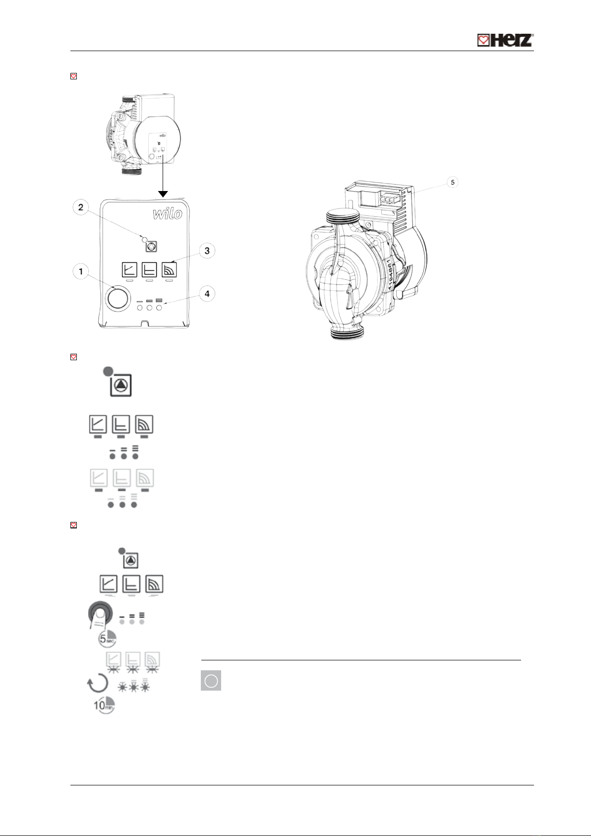
Product description
1. Operating button for pump adjustment
2. Run signal/fault signal LED
3. Display of selected control mode
4. Display of selected characteristic curve (I, II, III)
5. Mains connection: 3-pin plug connection
Indicator lights - LEDs
- Signal display
• LED is lit up in green in normal opertaion
• LED lights up/ashes in case of a fault
- Display of selected control mode Δp-v, Δp-c and constant speed
- Display of selected pump curve (I, II, III) within the control mode
- LED indicator combinations during the pump venting function, manual restart
and key lock
Commissioning
Commissioning only by qualied technicians.
The pump attempts an automatic restart upon detecting a blockage. If the pump
does not restart automatically:
- Activate manual restart via the operating button: press and hold for 5 seconds,
then release.
• The restart function is initiated, and lasts max. 10 minutes.
• The LEDs ash in succession clockwise.
- To cancel, press and hold the operating button for 5 seconds.
NOTICE
After the restart, the LED displays shows the previously set values of the
pump.
Page 5
HERZ - Mixing set
Pump data
Type: WILO PARA 15-130/6-43/SC
Thread: G 1"
Overall length: 130 mm
Energy Efficiency Index (EEI): ≤ 0,20
Max. delivery head: 6,7 m
Max. volume flow: 3,2 m3/h
Max. operating temperature: 100 °C
Maxi. operating pressure: 10 bar
Mains connection: 1~230 V +10%/-15%, 50/60 Hz (tensiune standard /IEC 8 standard voltage)
Protection class: IPx4D
Insulation class: F
Minimum suction head at suction port to avoid cavitation at water pumping temperature
Minimum suction head at 50/95 °C: 0.5 / 4.5 m
Pump hydraulic operation area
Product description
1 Operating button for pump adjustment
2 Run signal/fault signal LED
3 Display of selected control mode
4 Display of selected characteristic curve (I, II, III)
5 Mains connection: 3-pin plug connection
Indicator lights - LEDs
- Signal display
•LED is lit up in green in normal opertaion
•LED lights up/flashes in case of a fault
- Display of selected control mode Δp-v, Δp-c and constant speed
- Display of selected pump curve (I, II, III) within the control mode
- LED indicator combinations during the pump venting function, manual restart
and key lock
Commissioning
Commissioning only by qualified technicians.
Manual restart
The pump attempts an automatic restart upon detecting a blockage. If the pump
does not restart automatically:
-Activate manual restart via the operating button: press and hold for 5 seconds,
then release.
•The restart function is initiated, and lasts max. 10 minutes.
•The LEDs flash in succession clockwise.
-To cancel, press and hold the operating button for 5 seconds.
iNOTICE
After the restart, the LED displays shows the previously set values of the pump.
Page 5
HERZ - Mixing set
Pump data
Type: WILO PARA 15-130/6-43/SC
Thread: G 1"
Overall length: 130 mm
Energy Efficiency Index (EEI): ≤ 0,20
Max. delivery head: 6,7 m
Max. volume flow: 3,2 m3/h
Max. operating temperature: 100 °C
Maxi. operating pressure: 10 bar
Mains connection: 1~230 V +10%/-15%, 50/60 Hz (tensiune standard /IEC 8 standard voltage)
Protection class: IPx4D
Insulation class: F
Minimum suction head at suction port to avoid cavitation at water pumping temperature
Minimum suction head at 50/95 °C: 0.5 / 4.5 m
Pump hydraulic operation area
Product description
1 Operating button for pump adjustment
2 Run signal/fault signal LED
3 Display of selected control mode
4 Display of selected characteristic curve (I, II, III)
5 Mains connection: 3-pin plug connection
Indicator lights - LEDs
- Signal display
•LED is lit up in green in normal opertaion
•LED lights up/flashes in case of a fault
- Display of selected control mode Δp-v, Δp-c and constant speed
- Display of selected pump curve (I, II, III) within the control mode
- LED indicator combinations during the pump venting function, manual restart
and key lock
Commissioning
Commissioning only by qualified technicians.
Manual restart
The pump attempts an automatic restart upon detecting a blockage. If the pump
does not restart automatically:
-Activate manual restart via the operating button: press and hold for 5 seconds,
then release.
•The restart function is initiated, and lasts max. 10 minutes.
•The LEDs flash in succession clockwise.
-To cancel, press and hold the operating button for 5 seconds.
i
NOTICE
After the restart, the LED displays shows the previously set values of the pump.