HESCH HE 5411 User manual
# 340411 | Version 1.7
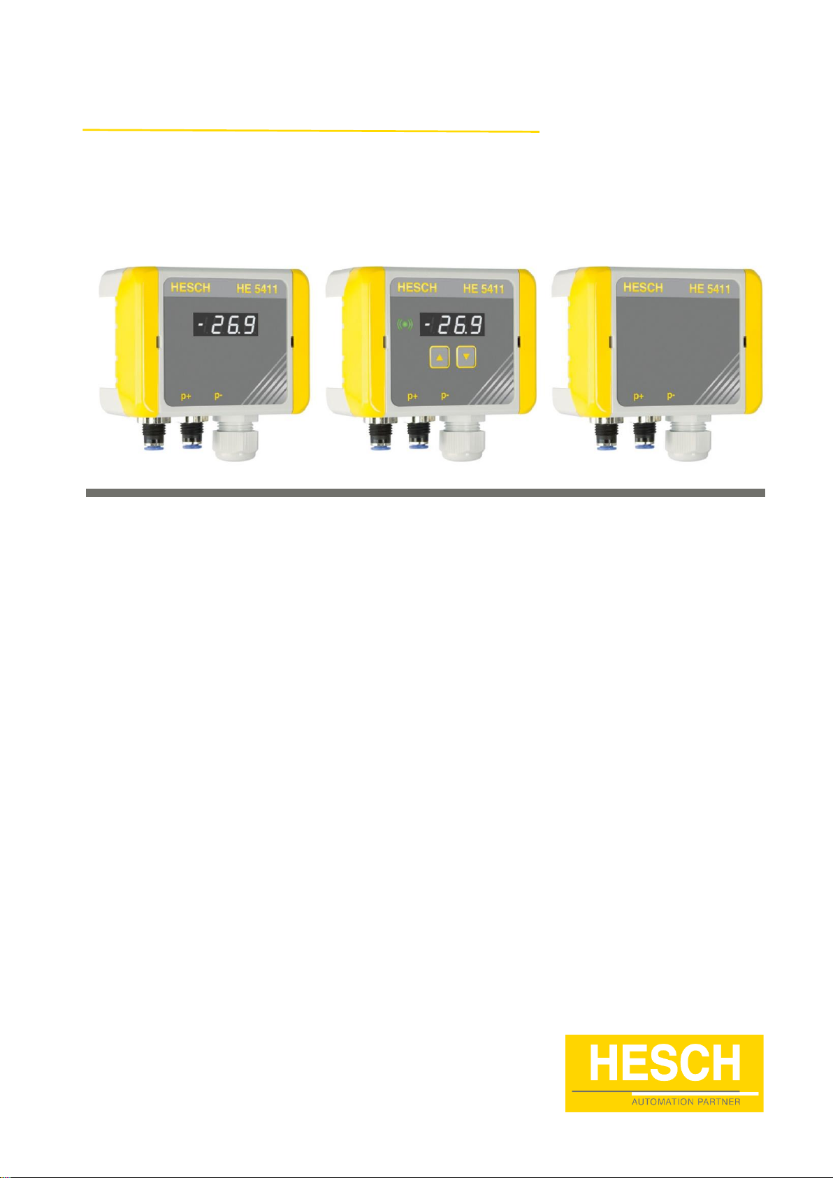
Differential pressure transducer with limit signal
HE 5411
Operating Instructions
(Translation of Original German version)

2
HE 5411 Operating Instructions
#340411 | version 1.7
Imprint
HESCH Industrie-Elektronik GmbH
Boschstraße 8
31535 NEUSTADT
GERMANY
Phone: +49 5032 9535-0
Fax: +49 5032 9535–99
Internet: www.hesch.de
Email: [email protected]
Hanover District Court
Commercial Register 111184
VAT.-Id. No. DE813919106
General Management
Walter Schröder, Werner Brandis
Editor:
HESCH Industrie-Elektronik GmbH, Documentation Department
Copyrights
© Copyright 2020 HESCH Industrie-Elektronik GmbH. All rights reserved.
The content including pictures and the design of these operating
instructions are subject to copyright protection and other laws for the
protection of intellectual property. The operating instructions may only be
distributed as a complete document and only with reference to the source.
The modification of the contents of this operating instructions is prohibited.
In addition, this content may not be copied, distributed, modified or made
available to third parties for commercial purposes.

HE 5411 Operating Instructions
#340411 | version 1.7
3
Document history
Date / Version
Description / Author
16.09.2019 / 1.0
First version / Bg
25.09.2019 / 1.1
Chapter 3: Basic accuracy and temperature drift
removed for analogue output; Chapter 8.1:
Adaptation of heading; Chapter 8.3: Steps 9 and
10 supplemented; Chapter 9: Note removed /
Bg
15.01.2020 / 1.2
Chapter 3: free from silicone, cable diameter
and mean times (MTBF, MTTF) added
Chapter 11: new article number for USB/TTL
adapter added / Bg
03.04.2020 / 1.3
Chapter 3: technical data for relay contact added
/ Bg
14.04.2020 / 1.4
Chapter 3: technical data for relay contact
adapted and service interface added / Bg
12.05.2020 / 1.5
All 24 VDC devices can now be used in EX zone
2 as well, except for the devices with a
measuring range of ±1.25 mbar (Sensirion
sensor).
Chapter 6.1 Electrical connections, Relay output
(limit value): graphical explanation
Chapter 8.5 Setting the measuring range: “mbar”
changed to “pressure”.
21.10.2020 / 1.6
Chapter 9.1 Parameter table: Damping and
creep flow suppression added after software
modification
Chapter 10 Error messages: Error E.CAL,
E. Sen. and E.Par added after software
modifications
08.12.2020 / 1.7
Chapter 3 Technical data: sensor with ± 350
mbar measuring range added / Bg

4
HE 5411 Operating Instructions
#340411 | version 1.7
TABLE OF CONTENTS
1LEGAL PROVISIONS................................................................................................................................... 5
2SAFETY INFORMATION ............................................................................................................................. 6
2.1 SYMBOLS AND BASIC SAFETY INSTRUCTIONS...................................................................................................... 6
2.2 SIGNAL WORDS ........................................................................................................................................... 6
2.3 SAFETY IN THE INDIVIDUAL OPERATING PHASES................................................................................................... 7
2.4 DEVICE IDENTIFICATION................................................................................................................................. 8
3TECHNICAL DATA.................................................................................................................................... 10
4MOUNTING ............................................................................................................................................ 13
4.1 DIMENSIONS ............................................................................................................................................. 13
4.2 OPENING THE DEVICE.................................................................................................................................. 14
4.3 MOUNTING THE DEVICE............................................................................................................................... 14
5DEVICE DESCRIPTION.............................................................................................................................. 15
5.1 SUMMARY OF DEVICE VERSIONS .................................................................................................................... 15
5.1.1 HE 5411 Lite (without limit signal)................................................................................................ 15
5.1.2 HE 5411 Basic (without limit signal) ............................................................................................. 15
5.1.3 HE 5411 Premium (with limit signal)............................................................................................. 15
6ELECTRICAL COMMISSIONING ................................................................................................................ 16
6.1 ELECTRICAL CONNECTIONS ........................................................................................................................... 17
6.2 ASSEMBLY OF MEASURING HOSE ONTO PRESSURE CONNECTION........................................................................... 18
7DISPLAY AND OPERATING ELEMENTS ..................................................................................................... 19
7.1 LIMIT LED ................................................................................................................................................ 21
7.1.1 “Limit threshold” mode ................................................................................................................. 21
7.1.2 “Limit window” mode.................................................................................................................... 22
8OPERATION ............................................................................................................................................ 23
8.1 OFFSET FOR ZEROING.................................................................................................................................. 23
8.2 OFFSET FOR ZEROING WITH DEVICE KEYPAD (HE 5411 PREMIUM)....................................................................... 24
8.3 LIMIT VALUE PARAMETER SETTING WITH DEVICE KEYPAD (HE 5411 PREMIUM)...................................................... 25
8.4 ANALOGUE OUTPUT SETTING ....................................................................................................................... 26
8.5 SETTING THE MEASURING RANGE................................................................................................................... 26
8.6 TEST MODE .............................................................................................................................................. 27
9PARAMETER SETTING WITH SERVICE PC ................................................................................................. 28
9.1 PARAMETER TABLE..................................................................................................................................... 29
10 ERROR MESSAGES............................................................................................................................... 36
11 ACCESSORIES ...................................................................................................................................... 37
12 MAINTENANCE AND SERVICE.............................................................................................................. 39

HE 5411 Operating Instructions
#340411 | version 1.7
5
1 Legal Provisions
Manufacturer
HESCH Industrie-Elektronik GmbH, Boschstraße 8, 31535 NEUSTADT, GERMANY
Intended use
The HE 5411 differential pressure transducer is a universal pressure transducer,
mainly used in dedusting technology. It can also be used in the measurement of
overpressure in clean rooms.
The device can be operated within the operating and environmental conditions
approved in these operating instructions without impairing its safety.
The manufacturer is not liable for improper use and any resulting personal injury or
material damage; the risk is borne solely by the user. Failure to comply with the above
criteria for intended use will result in the expiry of the warranty and liability for the
device.
Personnel qualification
All work on the differential pressure transducer may only be carried out by qualified electricians
with sufficient knowledge in the field of electrical engineering.
Device Safety
The device has been constructed and tested in accordance with VDE 0411 / EN 61010-1 and
has left the factory in perfect safety condition. To maintain this condition and ensure safe
operation, the user must observe the notes and warnings described in this manual.
Declaration of conformity
The valid declaration of conformity can be found on the internet on www.hesch.de.
6
HE 5411 Operating Instructions
#340411 | version 1.7
2 Safety Information
2.1 Symbols and Basic Safety Instructions
This chapter contains important safety regulations and notes. To protect against personal injury
and material damage, it is necessary to read this chapter carefully before working with the
device.
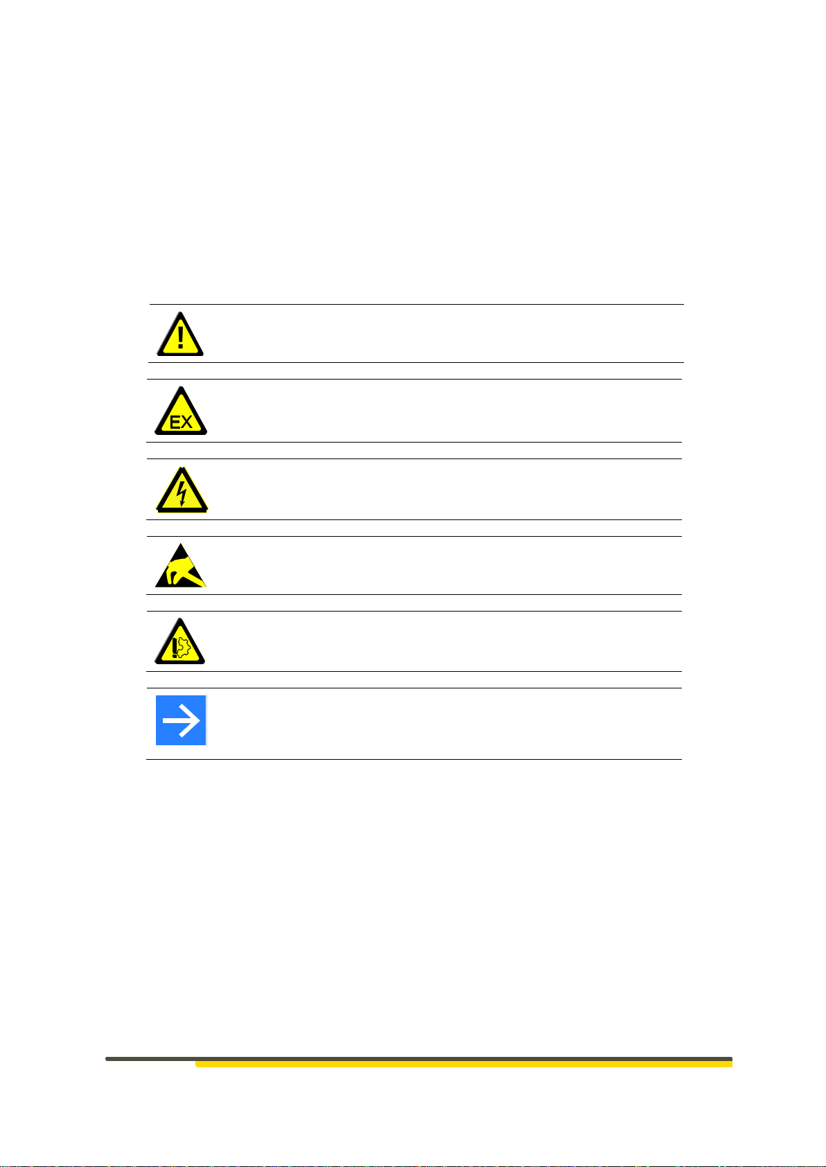
Symbols used
The following symbols are used in this manual. All safety instructions have a uniform structure.
Personal Injury Warning!
The severity of the danger is indicated by the respective signal word.
Explosive region warning sign!
High Voltage Warning!
Warning of material damage caused by electrostatic charge!
Property Damage Warning!
Note!
Identifies possible malfunctions and indicates optimum operating
conditions.
2.2 Signal Words
DANGER!
Indicates an imminently hazardous high risk situation, which, if not avoided, will result in death
or serious injury.
WARNING!
Indicates a potentially hazardous medium risk situation, which, if not avoided, could result in
death or serious injury.
CAUTION!
Indicates a hazardous low risk situation, which, if not avoided, could result in minor or moderate
injury.

HE 5411 Operating Instructions
#340411 | version 1.7
7
2.3 Safety in the individual operating phases
When installing the device and during operation, the following safety instructions must be
observed.
Danger of Electrocution!
Before working on the device, switch off all power supplies used. The
electrical cables must be laid according to the respective national
regulations (in Germany VDE 0100). The measuring lines must be laid
separately from the mains leads.
Attention!
The device must never be put into operation even if damage is
recognisable.
Warning!
Ensure protection against short circuiting in the supply circuit.
Attention!
During installation, commissioning, maintenance and troubleshooting,
observe the accident prevention regulations applicable to your system,
e.g. DGUV Regulation 3 "Electrical installations and equipment".
Attention!
Clean dirty contacts with oil-free compressed air or with spirit and a lint-
free cloth.
Warning of material damage caused by electrostatic charge!
Observe the safety measures according to BS EN 61340-51/-3 to avoid
electrostatic discharge!
Power Connection!
The electrical cables must be laid according to the respective national
regulations (in Germany VDE 0100). The measuring lines must be laid
separately from the mains leads.
Explosion Prevention!
HE 5411 Lite, Basic and Premium with a supply voltage of 19…36 V DC
are suitable for use in explosion zones 2 and 22, provided that the lid is
closed.
HE 5411 Lite, Basic and Premium with a supply voltage of 100…240 V
AC are only suitable for use in explosion zone 22, provided that the lid is
closed.
Devices with a measuring range of ± 1.25 mbar (regardless of the device
version) do not have an ATEX certification and must not be used in
potentially explosive areas.
Before opening the device, e.g. for parameter setting, it is essential to
ensure that no explosive environmental conditions, such as formation of
dust, exist.
8
HE 5411 Operating Instructions
#340411 | version 1.7
2.4 Device Identification
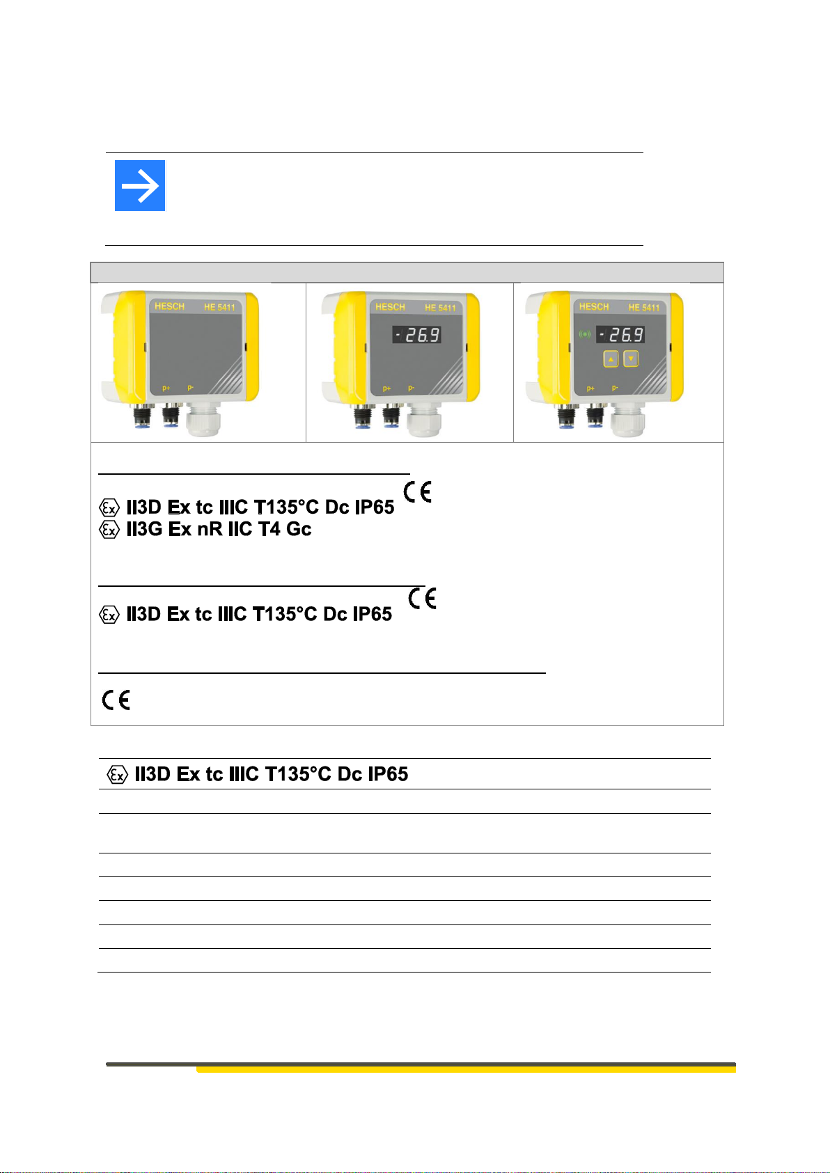
Note!
The HE 5411 differential pressure transducer is available in three
different designs. The corresponding device identification can be seen on
the nameplate. Devices with a measuring range of ± 1.25 mbar
(regardless of the device version) do not have any ATEX certification!
HE 5411 Lite
HE 5411 Basic
HE 5411 Premium
The devices with 19…36 V DC are marked with:
The devices with 100…240 V AC are marked with:
The devices with a measuring range of ±1.25 mbar are marked with:
II3D
Device category:
Use in Zone 22 for dust during normal operation
Ex
Denotes electrical equipment.
Standards of the EN 60079-0ff. series have been applied.
tc
Type of ignition protection:
Protection by housing
IIIC
Explosion group:
conductive dusts
T135°C
Temperature class:
maximum permissible surface temperature
Dc
Device protection level:
Use in Zone 22 for dust
IP65
Protection type:
dust-tight and protected against water jets
HE 5411 Operating Instructions
#340411 | version 1.7
9
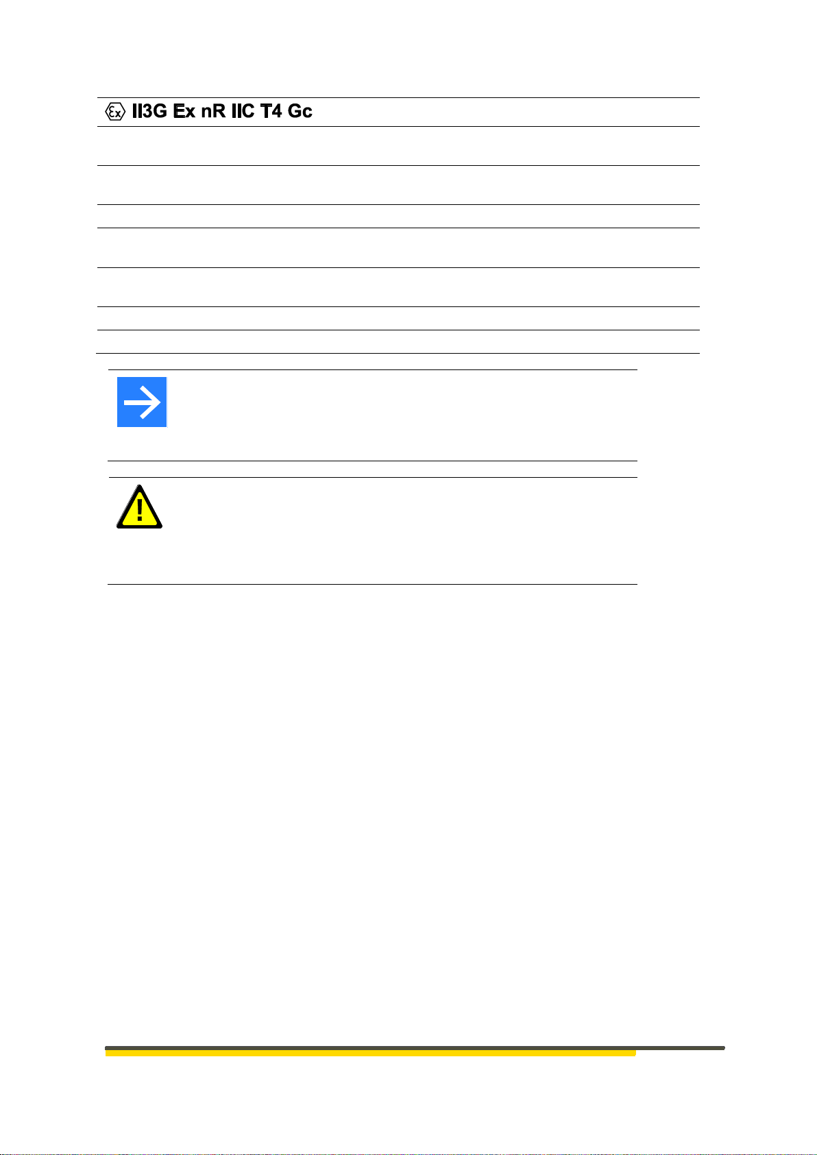
II3G
Device category/
Ex. Atmosphere:
Use in Zone 2 for gas during normal operation
Ex
denotes electrical equipment.
Standards of the EN 60079-0ff. series have been applied.
nR
Type of ignition protection:
Protection by restricted breathing housing
IIC
Explosion group:
Certified for gases with an ignition power of <60µJ
(e.g. hydrogen)
T4
Temperature class:
maximum permissible surface temperature
(135°C)
Gc
Device protection level:
Use in zone 2 for gas
IP65
Protection type:
dust-tight and protected against water jets
Troubleshooting!
At the beginning of troubleshooting, all possible sources of faults on
additional devices or supply lines (measuring lines, wiring, downstream
devices) should be taken into consideration. If the fault is not found after
checking these points, we recommend sending the device to the supplier.
Decommissioning!
Switch off the power supply on all poles if the device is to be
decommissioned. Secure the device against unintentional operation!
If the device is connected to other devices and / or equipment, the effects
must be considered and appropriate precautions taken before switching
off.
The following special regulations must be observed:
The cables must be correctly inserted through the cable ducts by a professional.
Cable ducts not required must be furnished with sealing bolts by a professional.
The ATEX certification only maintains its validity if the installation is carried out correctly by a
professional under the safeguarding of the protection class specified on the marking.
Cleaning of the housing is only permitted with moist cleaning materials to avoid static charging.
Cleaning is necessary to prevent increased dust generation on the device.
Operation under voltage, in zone 22 and 2, only in closed state.
Before closing, ensure that the device housing is free of dust.
10
HE 5411 Operating Instructions
#340411 | version 1.7
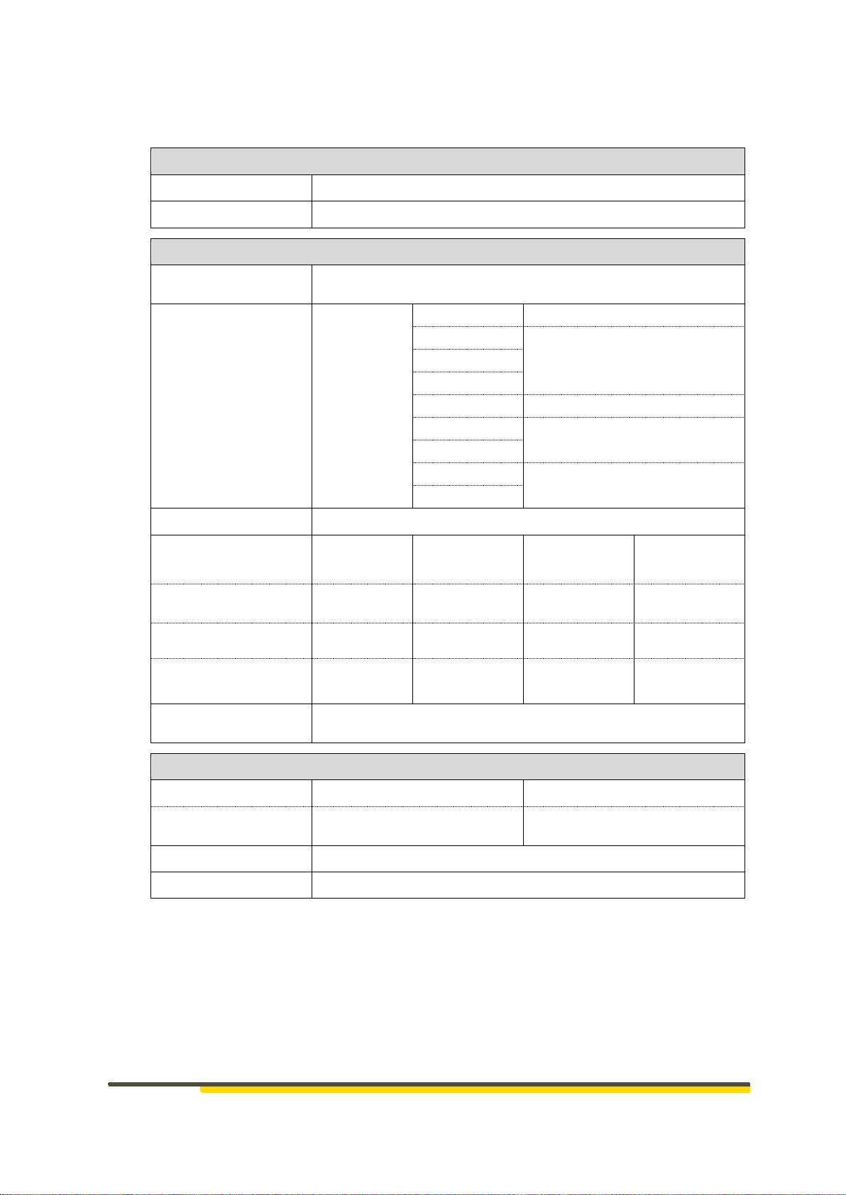
3 Technical Data
Electric supply
Voltage
19…36 V DC or 100…240 V AC
Power consumption
Max. 2 W
Sensor system
Measuring range
(mbar)
± 1.25, ± 2.5, ± 5, ± 10, ± 25, ± 50, ± 100, ± 350, ± 1000
in accordance with the information on the name plate
Max. differential
pressure
Measuring
range
± 1.25 mbar
< 1 bar
± 2.5 mbar
< 0.35 bar
± 5 mbar
± 10 mbar
± 25 mbar
< 0.5 bar
± 50 mbar
< 1 bar
± 100 mbar
± 350 mbar
< 5 bar
± 1000 mbar
Medium
Air and dry, non-aggressive gases
Measuring system
Thermal
(Bypass
Technology)
Piezoresistive
Piezoresistive
Piezoresistive
Measuring ranges
(mbar)
± 1.25
± 2.5…± 10
± 25…± 100
± 350…± 1000
Basic accuracy
-
± 1.5 % FSO
T = 25 °C
± 1.0 % FSO
T = 25 °C
± 0.5 % FSO
T = 25 °C
Total error
± 3 % FSO
T = -20…85°C
± 2 % FSO
T = 0…60°C
± 1.5 % FSO
T = 0…60°C
± 1.0 % FSO
T = 0…60°C
Pressure connection
Push-in bulkhead fittings for 6 mm hose –outer diameter (4 mm
with reduction, see chapter 11 Accessories)
Input / Output
Analogue output:
0…10 V
0(4)…20 mA
Max. permissible
load
RL ≥1 kΩ
RA ≤500 Ω
Relay output
1 changeover contact 250 VAC, 5 A as limit value relay
Service interface
USB / TTL adapter HE 5851 required (see chapter 11 Accessories)
FSO = Full Scale Output

HE 5411 Operating Instructions
#340411 | version 1.7
11
Housing
Type
Dust-tight polycarbonate housing
Dimensions
113 × 80 × 60 (W × H × D)
113 × 110 × 60 (W × H × D) incl. connection
coupling
Protection type
IP 65
Mounting
Wall-mounted, vertical mounting position
Cable gland
1 × M20 × 1,5 N (for cable diameters 6-12 mm)
with multiple sealing insert for 2 x cables Ø 6
mm
Identification
Device identification/explosion protection
See chapter 2.4 Device Identification
Climatic environmental conditions
Storage
-20°…+60° C
Transport
-20°…+85° C
Operation
-20°…+55° C
In EX zone: -20 °C…+40 °C
Relative air humidity
75% rel. humidity, no condensation
Air and creepage distances
Pollution degree
2
Overvoltage category
II
Material group
IIIa
Rated voltage
< 150 V AC, ≤ 250 V AC
Test voltage (basic insulation):
1250 V AC, 1 min
Test voltage (added insulation):
3000 V AC, 1 min
Power connection
Connection type
Push-in-spring connection
Wire size
0.2 mm²…1.5 mm²
Flexible wire size
0.2 mm²…1.5 mm²
AWG wire size / kcmil
24…16
Flexible wire size with ferrule without
plastic sleeve
0.2 mm²…1.5 mm²
Flexible wire size with ferrule with plastic
sleeve
0.2 mm²…0.75 mm²
Extras
Special characteristics
Free from silicone1
1
Silicone is not used in the production process.

12
HE 5411 Operating Instructions
#340411 | version 1.7
Mean Time Between Failures
MTBF [a2]
Power supply
19…36 V DC
without limit
signal
Power supply
100…240 V AC
without limit signal
Power supply
19…36 V DC
with limit signal
Power supply
100…240 V AC
with limit signal
Without
display
545
167
-
-
With
display
486
161
431
119
Mean Time to Dangerous Failure
MTTFd[a]
Power supply
19…36 V DC
without limit
signal
Power supply
100…240 V AC
without limit signal
Power supply
19…36 V DC
with limit signal
Power supply
100…240 V AC
with limit signal
Without
display
1090
334
-
-
With
display
972
322
862
238
2
anno
HE 5411 Operating Instructions
#340411 | version 1.7
13
4 Mounting
The ambient temperature at the installation point must not exceed the
permissible temperature for nominal use specified in the technical data. The special regulations
for use in EX ATEX Zones must be observed (see chapter 2.3 Safety in the individual operating
phases)
Note!
A drill template can be found on the internet on: www.hesch.de.
When you print it, please ensure to print out Document 1:1.
Ensure the size accuracy of the print-out before drilling.
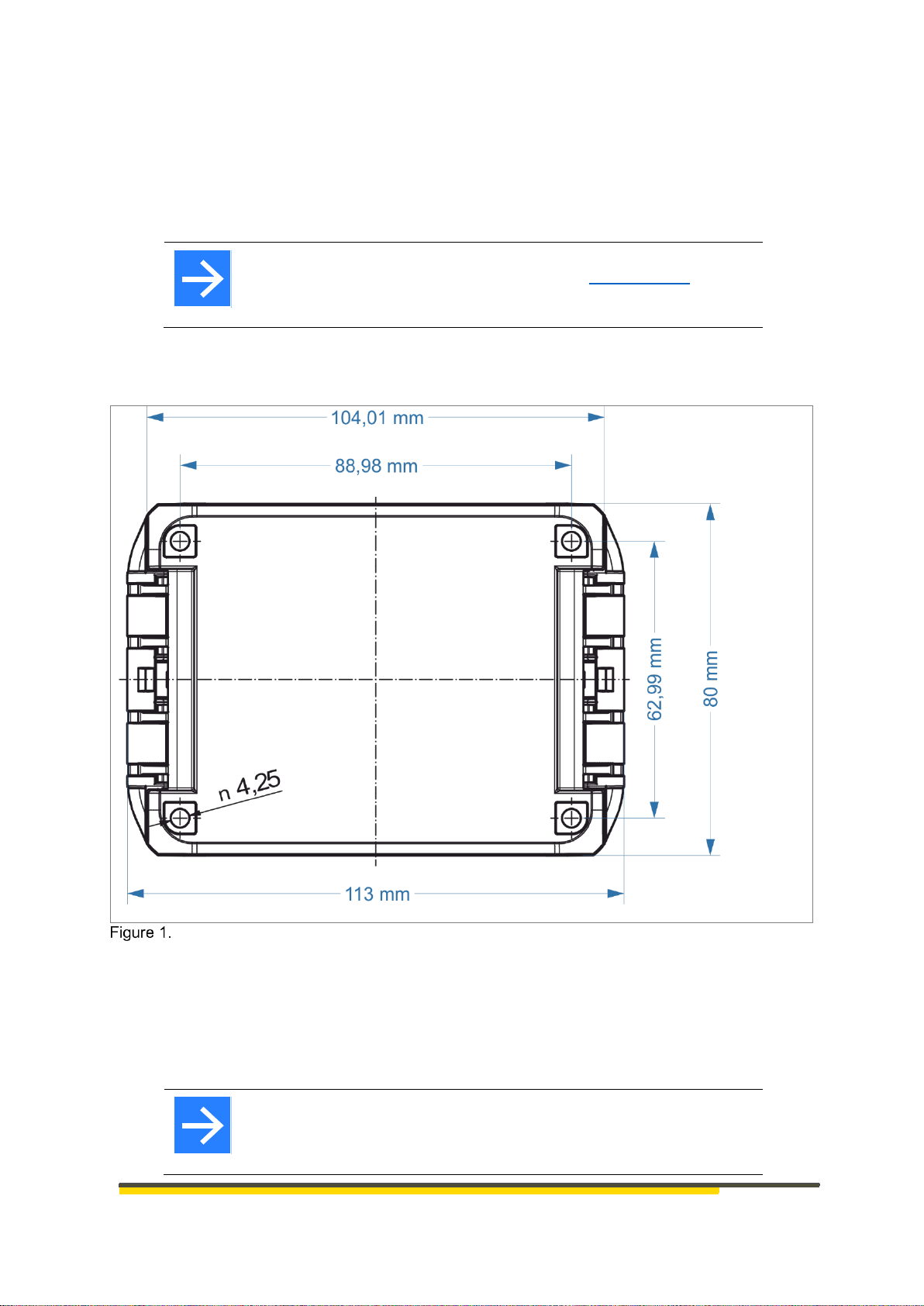
4.1 Dimensions
Back of housing
The dimensions including the connection couplings are 113 × 110 × 60 mm.
Scope of Delivery
HE 5411 differential pressure transducer
Operating Instructions
Note!
Upon receipt, check the delivery for completeness and visible defects. In
the event of a complaint, contact your responsible HESCH representative
immediately.
14
HE 5411 Operating Instructions
#340411 | version 1.7
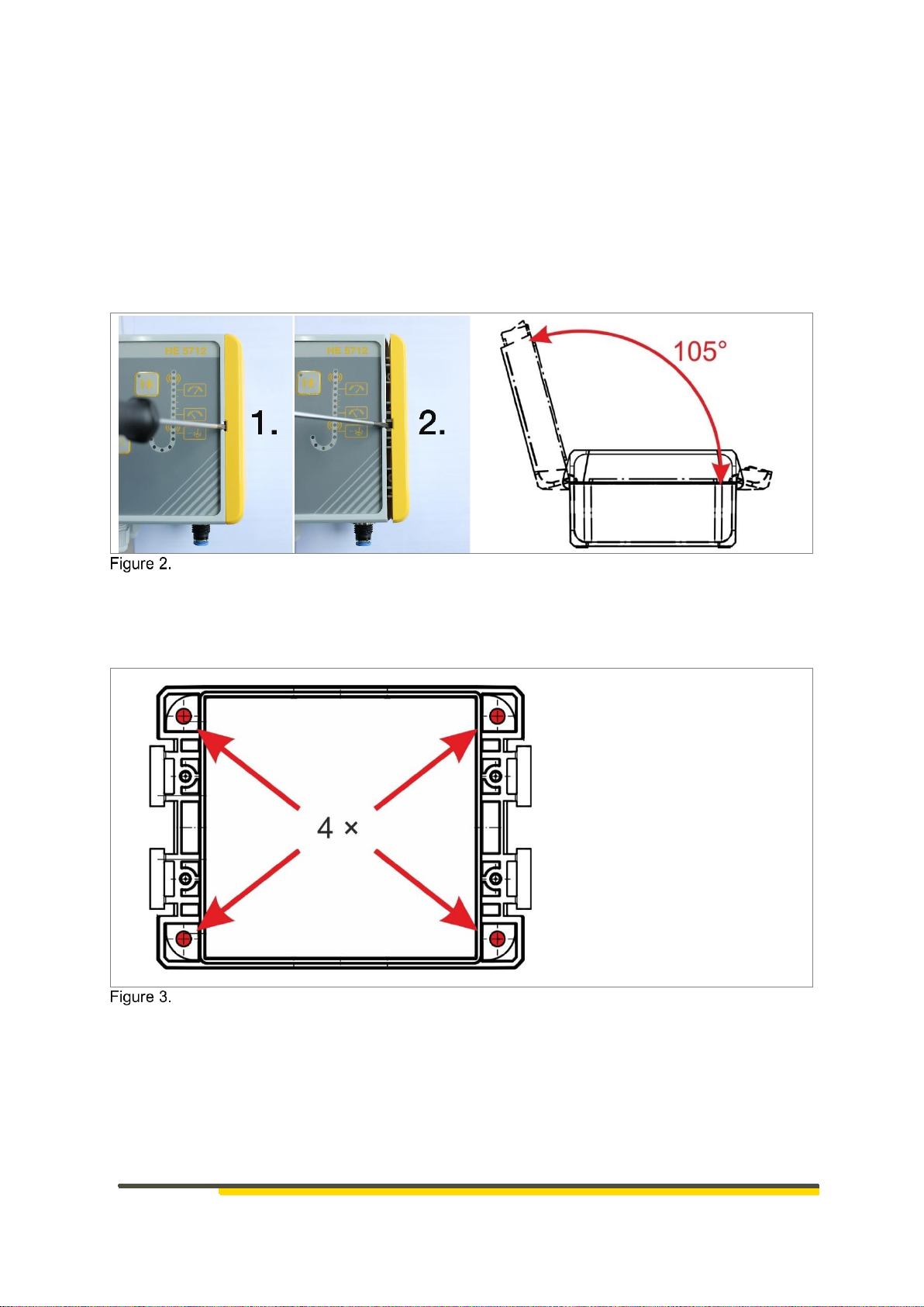
4.2 Opening the device
The opening and closing is without screws by means of hinge technology. A flat-tip screwdriver
is needed to open the device. Apply the screwdriver to the position intended for this on the
housing lid, in order to lift up the hinge. Open the case cover to the left up to an angle of 105°.
Optionally, the housing lid can be closed with 4 additional screws (see chapter 11 Accessories)
in order to protect it from unauthorised access.
The screwless hinge closure is recommended for rapid service access.
Open the housing lid to the left. (The illustration does not show the HE 5411, but one with
a structurally identical housing. The opening principle is identical.)
4.3 Mounting the device
4 screws are required to fasten the device to the wall. (Not included in the scope of delivery!)
Base of the housing
Alternative: Fastening to the wall with wall brackets. (see chapter 11 Accessories)

HE 5411 Operating Instructions
#340411 | version 1.7
15
5 Device Description
The differential pressure transducer records the differential, over- and negative pressure
between two pressure inputs, and converts the measurement value into a linear or square-
rooted output signal of 0(4)…20 mA or 0…10 V.
The 4-digit 7-segment display also allows the display of negative pressures.
5.1 Summary of device versions
5.1.1 HE 5411 Lite (without limit signal)
Front view HE 5411 Lite
5.1.2 HE 5411 Basic (without limit signal)
Front view HE 5411 Basic
5.1.3 HE 5411 Premium (with limit signal)
Front view HE 5411 Premium

16
HE 5411 Operating Instructions
#340411 | version 1.7
6 Electrical Commissioning
HE 5411 differential pressure transducer, 24 V DC (interior view)
.
Note!
Before commissioning, please note the information on the nameplate!
A
B
C
D
+ -
D
HE 5411 Operating Instructions
#340411 | version 1.7
17
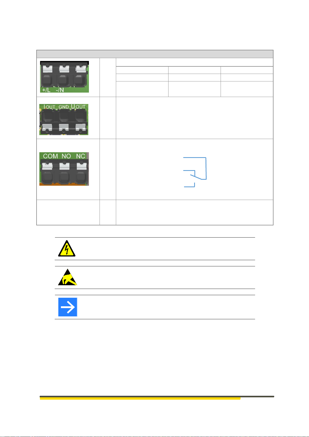
6.1 Electrical connections
Connections
Meaning
B
Supply voltage (Figure 7 shows 24 V DC device)
Connection
DC Signal Version
AC Signal Version
+/L
19…36 V DC
100…240 V AC
-/N
GND
N
A
Analogue output
I OUT Current output 0(4)…20 mA
GND GND
U OUT Voltage output 0…10 V
C
Relay output (limit value)
D
Pressure inputs
The pressure inputs are to be connected with the shortest
possible hoses. These hoses must be:
p+ (raw gas) larger than p- (clean gas)
Danger of Electrocution!
Electrical installation must only be carried out when the power is
disconnected.
Warning of material damage caused by electrostatic charge!
Observe the safety measures according to DIN EN 61340-51/-3 to avoid
electrostatic discharge!
Note!
Work on the electronics may only be carried out by qualified personnel.
Take the value of the correct supply voltage from the nameplate!
There are device versions with 100-240 V AC and device versions with 19-36 V DC supply
voltage.
Before switching on the device, observe the following points:
The cables must have been connected by a professional.
The power supply must correspond to the voltage indicated on the nameplate.
The device may only be operated in closed condition.
The temperature restrictions specified for the use of the device must be observed before
and during operation.
COM
NC
NO
18
HE 5411 Operating Instructions
#340411 | version 1.7
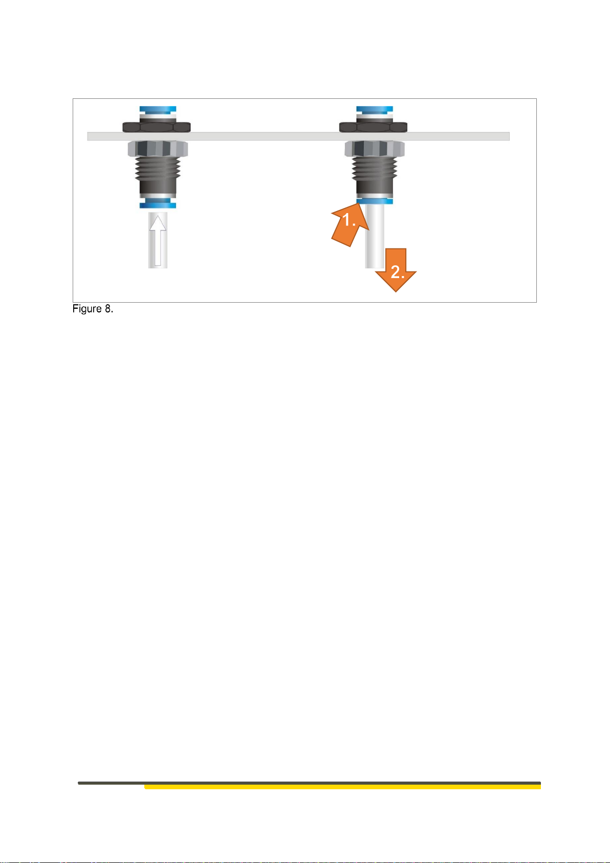
6.2 Assembly of measuring hose onto pressure connection
Assembly of hose onto push-in bulkhead fitting
A Hose connection
Insert hose with 6 mm outer diameter into the connection.
B Hose disconnection
1. Press the blue retaining ring to open the lock.
2. Pull the hose out of the connection.
A
B
1. Push
2. Pull hose
HE 5411 Operating Instructions
#340411 | version 1.7
19
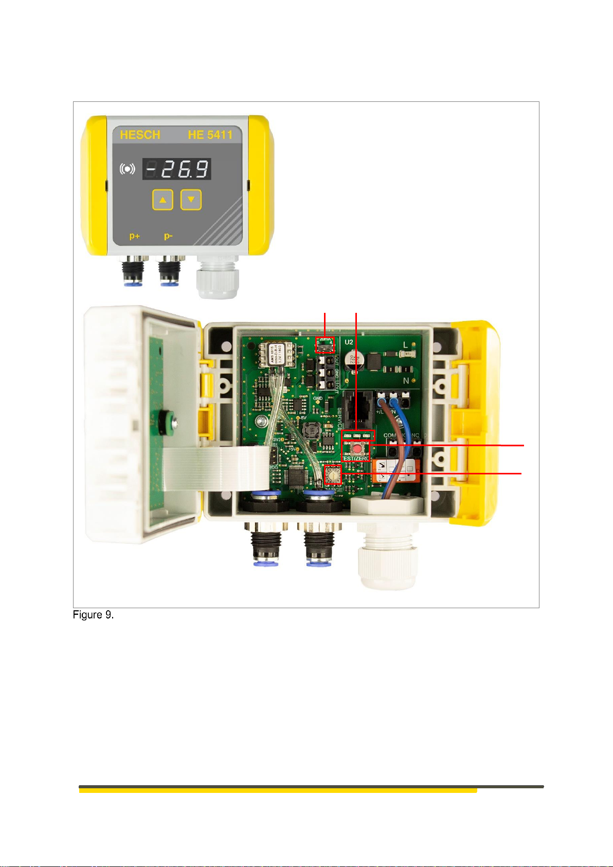
7 Display and Operating Elements
HE 5411 Premium Display and Operating Elements (outside and inside)
A 0(4)…20 mA switch
B LEDs
C Test button
D Rotary coding switch
C
A
D
B

20
HE 5411 Operating Instructions
#340411 | version 1.7
Symbols/Displays
Meaning
UP key: increase the displayed value
DOWN key: decrease the displayed value
Three-coloured Limit LED with colour changes to show status.
Display:
• Normal operation: current differential pressure
• Parameter setting mode: Limit value set
• Switch between the two with UP / DOWN keys
A
The slide switch lets you switch the analogue output between
0…20 mA (left)
4…20 mA (right)
B
LEDs (from left to right)
Flashes continuously (o—o—o—o) when the differential pressure
is in the range of ± 10 % from the measuring range end value to
the zero point.
Flashes continuously (o-o—o-o—o-o), when an offset has been
programmed.
Lights up as soon as the supply voltage is present
Lights up when the differential pressure measured is ≥ the limit
value set
Flashes when the device is in test mode
C
TEST button for zeroing / Test mode
D
Rotary coding switch, 16 levels (0…F) to set the measuring
range.
Table of contents
Other HESCH Transducer manuals

Popular Transducer manuals by other brands


Agilent Technologies
Agilent Technologies IMG-300 instruction manual

Siemens
Siemens Echomax XCT Series Operation manual

Camille Bauer
Camille Bauer SINEAX I 542 operating instructions

GHM Greisinger
GHM Greisinger GRMU2000 MP operating manual

Thyracont
Thyracont VSC43MV operating instructions

Daiichi Electronics
Daiichi Electronics AETT2-91A instruction manual