HESCH HE 5409 User manual

Version # 341539 1.4
Differential pressure measuring
transducer
HE 5409
Operating instructions
(Original in German)

HESCH Industrie-Elektronik GmbH
2
HE 5409, version 1.4, # 341539
Legal information
HESCH Industrie-Elektronik GmbH
Boschstrasse 8
31535 Neustadt
Telephone: +49 5032 9535–0
Fax: +49 5032 9535-99
Website: www.hesch.de
Local court of Hanover
Commercial register (under HRB 111184)
VAT no.: DE813919106
Management:
Walter Schröder, Werner Brandis
Publisher:
HESCH Industrie Elektronik GmbH, documentation department
Document historyfor item no. # 341539
Date - version
Description
31.08.2017 / 1.0
Revised version according to redesign of device
08.3.2018 / 1.1
Cover picture updated
27.03.2019 / 1.2
Chapter 6 Technical data: Operating
temperature in EX Zone added
12.08.2019 / 1.3
Chapter 3.1: bilingual type label added
Chapter 5: clean gas / raw gas corrected
20.01.2020 / 1.4
Chapter 6: new cable connection M 20, because
from now on the housing of HE 5411 is used
(according to change request 5409xxx from
18.09.2019)
Copyrights
© Copyright 2020 HESCH Industrie-Elektronik GmbH Copyrights reserved
Content including illustrations and design of these operating instructions are
subject to copyright protection and other laws for the protection of
intellectual property. The distribution or modification of the content of these
operating instructions is not allowed. Moreover, this content shall not be
copied, distributed, modified or made accessible to third parties for
commercial purposes.

HESCH Industrie-Elektronik GmbH
HE 5409, version 1.4, # 341539
3
Table of content
1. Legal conditions....................................................................................... 4
2. Safety instructions................................................................................... 5
2.1 Symbols and general safety instructions ............................................................................ 5
2.2 Signal words........................................................................................................................ 5
2.3 Safety during the individual operating phases.................................................................... 6
2.4 Device identification............................................................................................................ 7
3. Device description ................................................................................... 9
3.1 Device view......................................................................................................................... 9
4. Assembly ................................................................................................ 10
5. Commissioning ...................................................................................... 12
6. Technical data ........................................................................................ 14
7. Accessories............................................................................................ 15
8. Maintenance and service....................................................................... 16

HESCH Industrie-Elektronik GmbH
4
HE 5409, version 1.4, # 341539
1. Legal conditions
Manufacturer
HESCH Industrie-Elektronik GmbH, Boschstrasse 8, D-31535 Neustadt, Germany
Intended use
The differential pressure measuring transducer HE 5409 is an universal measuring
transducer for small and medium pressures.
The device can be operated within the authorised application and ambient conditions
without compromising its safety.
The manufacturer is not liable for improper use and personal and material damages
resulting thereof; the user bears the risk alone. Not complying with the above mentioned
criteria regarding the intended use will result in expiration of warranty and liability for the
device.
Qualification of personnel
Only skilled electricians with sufficient knowledge in electrical engineering shall perform all
work at the measuring transducer.
Device safety
The device has been built and tested according to VDE 0411 EN 61010-1 and has left the
factory in a safety-related impeccable condition. The user must observe the mentioned
instructions and warnings in this manual to keep this condition and to ensure a safe operation.
Declaration of conformity
Please refer to www.hesch.de
for a valid declaration of conformity.

HESCH Industrie-Elektronik GmbH
HE 5409, version 1.4, # 341539
5
2. Safety instructions
2.1 Symbols and general safety instructions
This chapter consists of important safety regulations and instructions. Prior to operating the
device, it is mandatory to read this chapter thoroughly to prevent personal and material
damages.
Symbols used
Following symbols are used in these operating instructions. All safety instructions are
standardised.
Warning against personal injuries!
The respective signal word indicates the level of danger.
Warning against explosive atmosphere!
Warning against dangerous electrical current!
Warning against material damages due to electrostatic loading!
Warning against material damages!
Please note!
Indicates possible malfunctioning and provides instructions for optimal
operating conditions.
2.2 Signal words
DANGER!
Indicates an immediate danger with high risk, which can lead to death or severe personal injury
if it is not prevented.
WARNING!
Indicates an immediate danger with medium risk, which can lead to death or severe personal
injury if it is not prevented.
CAUTION!
Indicates an immediate danger with low risk, which can lead to minor or moderate personal
injury if it is not prevented.

HESCH Industrie-Elektronik GmbH
6
HE 5409, version 1.4, # 341539
2.3 Safety during the individual operating phases
Following safety instructions must be observed during the assembly of the device.
Danger due to electric shock!
All utilised power supplies must be switched off prior to the work. The
electric cables must be installed according to the respective country
regulations (German VDE 0100). The measuring cables must be installed
separately from the power cord. The connection between the protective
ground conductor connection (in the respective device carrier) and a
protective ground conductor must be established.
Danger due to electric shock!
Due to any disconnection of the protective ground conductor in the device
carrier the device can become dangerous. Intended disconnections are not
permitted. The device must be shut down and secured against unintended
use in case it is assumed that a safe operation is no more possible.
Danger due to electric shock!
Do not open live devices! Active parts can be exposed during opening
devices or removing covers. Connection points can be active as well!
Attention!
The device shall never be operated despite visible defects.
Attention!
Observe the applicable accident prevention regulations for your system,
such as e.g. the German Statutory Accident Insurance Association
(DGUV) regulation 3 "electrical systems and operating materials" during
assembly, commissioning, maintenance and removal of defects.
Attention!
Clean contaminated contacts with oil-free compressed air or spirit and a
lint-free cloth.
Material damages due to electrostatic loading!
Observe the safety measures according to DIN EN 61340-51/-3 to prevent
an electrostatic loading!
Electrical connection!
The electric cables must be installed according to the respective country
regulations (in Germany VDE 0100). The measuring cables must be
installed separately from the power cord. The connection between the
protective ground conductor connection (in the respective device carrier)
and a protective ground conductor must be established.
Explosion protection!
It is permitted to use the device in explosion zone 22 and 2 with closed
lid. It is mandatory to ensure that no explosive ambient conditions, such
as e.g. development of dust, exist prior to opening the device for e.g.
parametrisation.

HESCH Industrie-Elektronik GmbH
HE 5409, version 1.4, # 341539
7
2.4 Device identification
The device bears the following label:
II3D
Device category:
Use in zone 22 for dust in standard operation.
Ex
Indicates an electrical operating material standards of series EN 60079-0ff. were
applied.
tc
Ignition protection type:
Protection by housing
IIIC
Explosion group:
Conductive dust
T135 °C
Temperature setting:
Maximum permitted surface temperature
Dc
Device protection level:
Use in zone 22 for dust
IP65
Protection type:
Dust proof and splash-water protected
II3G
Device category/
Ex-atmosphere:
Use in zone 2 for gas in standard operation
Ex
Indicates an electrical operating material.
Standards of series EN 60079-0ff. were applied
nR
Ignition protection type:
Protection by smoke-restricted housing
IIC
Explosion group:
Permitted for gases with an ignition power of <60µJ
(e,g. hydrogen)
T4
Temperature setting:
Maximum permitted surface temperature (135 °C)
Gc
Device protection level:
Use in zone 2 for gas
IP65
Protection type:
Dust proof and splash-water protected
Troubleshooting!
All possibilities of trouble sources at add-on devices respectively supply
lines (measuring lines, wiring, sequential devices) must be considered at
the beginning of the troubleshooting. We recommend to send the device
to the supplier in case the error has not been detected after reviewing
these points.
Decommissioning!
Disconnect the power supply at all poles to decommission the device.
Secure the device against unintended operation!
Prior to the disconnection the impacts must be considered and respective
measures must be taken if the device is connected to other devices and /
or equipments.

HESCH Industrie-Elektronik GmbH
8
HE 5409, version 1.4, # 341539
Following special regulations must be observed:
Cables must be professionally connected in the screw fitting.
Not required housing bores must be professionally closed by a locking bolt.
The ATEX certification remains valid only if the installation is professionally performed according to
the protection type mentioned on the labelling.
The housing shall only be cleaned with damp cleaning cloths to prevent static loading.
Cleaning is required to prevent increased dust on the device.
Operation at live parts, in zone 22, only in closed condition.
Ensure the device housing is dust-free prior to closing it.

HESCH Industrie-Elektronik GmbH
HE 5409, version 1.4, # 341539
9
3. Device description
3.1 Device view
Assembly of measuring hose at the pressure connection
Illustration 1. Assembly of hose at push-in bulkhead connector
A Connect hose
Push hose with 6 mm outer diameter into the connection.
B Release hose
1. Press on the blue locking ring to open the closure
2. Pull the hose out of the connection
1. Press
2. Pull hose
Pressure connection and supply
line for electrical connection
Type label
A
B

HESCH Industrie-Elektronik GmbH
10
HE 5409, version 1.4, # 341539
4. Assembly
Please note!
Regarding a drilling template please refer to our website:
www.hesch.de
Please ensure during printing that the document is printed 1:1. Ensure
the dimensional accuracy of the printout prior to drilling.
The assembly of the measuring transducer HE 5409 should possibly not take place in the
vicinity of heat sources. The ambient temperature at the assembly site must not exceed the
permitted nominal temperature for operation mentioned in the "Technical Data" (page 14). It is
permitted to assemble the device in areas of explosion class EX ATEX zone 22 and 2. The
special regulations must be observed, see chapter 2.4 device identification on page 7.
Dimensions
Illustration 2. Reverse side of the housing
Scope of delivery
HE 5409
Operating instructions
Please note!
After receipt, check the delivery for completeness and visible defects.
Immediately inform your respective HESCH agent in case of a claim.

HESCH Industrie-Elektronik GmbH
HE 5409, version 1.4, # 341539
11
Opening of the device
Opening and closing is performed by hinge technology without screws. A slit screwdriver is
required to open the device. The screwdriver must be positioned at the intended position at
the housing lid to break the hinge open. The housing lid must be opened to the left up to an
angle of 105 °.
Optional, in addition, the housing lid can be closed by 4 screws (see accessory list, item no.3
on page 15) to protect it from unauthorised access.
The hinge closure without screws is recommended for a quick service access.
Illustration 3. Open housing lid to the left
Assembling of the device
Screws are required for wall mounting. (Not included in the scope of delivery)
Illustration 4. Housing base
Alternative: wall mounting with wall brackets. (See accessories list on page 15, chapter 7)

HESCH Industrie-Elektronik GmbH
12
HE 5409, version 1.4, # 341539
5. Commissioning
Illustration 5. HE 5409 with open housing lid
A Zero point setting
Please note!
The correct value of the device has been set in the factory and does not
need to be changed.
A warm-up time of 30 minutes must be considered if the zero point must be set.
The zero point of the measuring transducer is set on 4 mA by the potentiometer.
B Test switch
The output signal can be switched from 4...20 mA to 10 mA by the switch to control the correct
connection.
C Pressure inputs
The pressure inputs must be connected via short hoses.
Attention: p+ (raw gas) greater than p- (clean gas).
+-
A
B
D
C

HESCH Industrie-Elektronik GmbH
HE 5409, version 1.4, # 341539
13
D Electrical connection
The device is suitable for the connection at 10…36 V DC. Pay attention to the correct value of
the power supply voltage. Otherwise the device will be destroyed.
The connection takes place via spring force terminals for 0.2 … 1.5 mm² conductors.
The input is bipolar and can be connected as needed. The measuring value of the differential
pressure corresponds to the power consumption of the device.
Connection diagram
Mains
10…36
V DC
HE 5409
(bipolar)
Measuring
input
4…20 mA
HESCH Industrie-Elektronik GmbH
14
HE 5409, version 1.4, # 341539
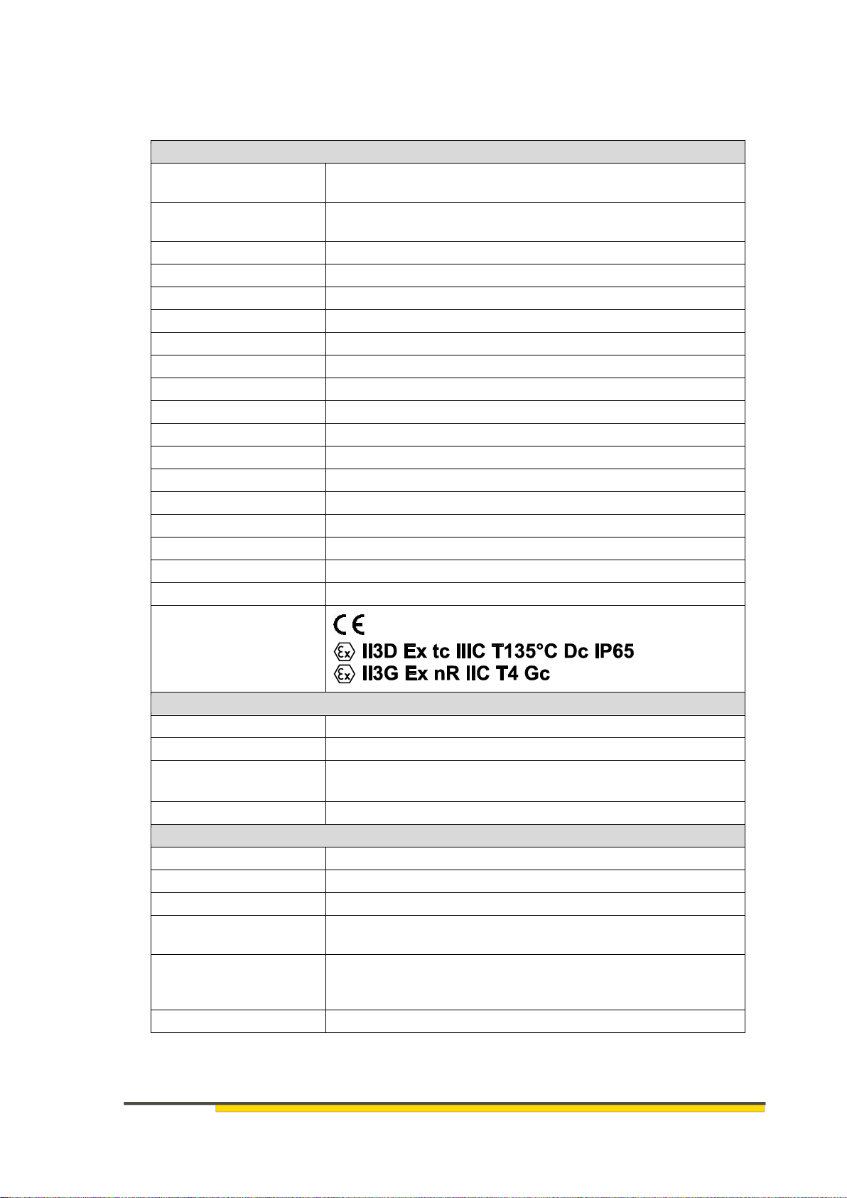
6. Technical data
Technical data
Measuring range
0–10 mbar; 0–25 mbar; 0–50 mbar; 0–100 mbar; 0–1000 mbar
According to the information on the type label
Max. differential
pressure
750 mbar
Max. ambient pressure
1000 mbar
Medium
Air and dry, not aggressive gases
Basic accuracy
± 1 % of final value
Temperature drift
± 0.05 % / K of final value
Hysteresis
± 0.05 % / of final value
Measuring system
Semiconductor sensor
Auxiliary power
Ub= 10…36 V DC
Analogue output
4…20 mA, 2-conductor technology
Max. load resistance
RA≤ (Ub–9 V) / 0.02 A
Pressure connection
Push-in bulkhead connectors for 6 mm hose outer diameter
Housing
Dust-protected housing
Dimension
113 × 80 × 60 (W × H × D)
Protection type
IP 65
Assembly
Wall mounting, assembly position vertical
Connection
Spring force terminal
Cable screw connector
1 × M 20 × 1.5 N for cable diameters of 6…12 mm
Device identification/
explosion protection
Climatic ambient conditions
Storage
-20 ° … +70 °C
Transport
-40 ° … +85 °C
Operation
-20 ° … +55 °C
In EX zone: -20° C…+40° C
Relative humidity
75 % relative humidity, no condensation
Safety related operating figures
MTBF
646 years
MTTFd
1292 years
Service life
Max. 10 years
Category according to
EN-ISO 13849
B
Calculation methods
according to EN-ISO
13849
Parts count
Ambient temperature
50 °C
Subject to technical modifications!

HESCH Industrie-Elektronik GmbH
HE 5409, version 1.4, # 341539
15
7. Accessories
Hesch offers a series of optimal accessories for assembly and connection technology of HE
5409
Item
no.
Illustration
Name
Order number
1
Wall brackets
for alternative
mounting of housing of
HE 5409
Colour:
Light grey
Upon request
2
Housing hinge closure
Available in different
colours:
Light grey, graphite grey,
bright red, ultramarine
blue
Upon request
3
Screw set (4 pc.)
for optimal screw
connection of the
housing
Factory standard 1412,
30×18×10, crosspoint,
left hand thread
B SHR
4
p-connector set
for HE 54xx and p-
magnetic valve controls.
PVC hose
Ø i=4 mm Ø a=6 mm
# 54109999
5
Universal adapter set
for push-in screw, PU
hose Ø i=4 mm / Ø a=6
mm
on Whitworth pipe thread
G¼"
# 54210099
Accessories for magnetic valve controls
6
HESCH premium valve cable
Incl. of plug and core end sleeve
0.65 m
# 63500006
2.50 m
# 63500002
5.00 m
# 63500003
8.00 m
# 67250004

HESCH Industrie-Elektronik GmbH
16
HE 5409, version 1.4, # 341539
8. Maintenance and service
Maintenance and repair
The device must be cleaned regularly to prevent increased dust on the device.
Disposal
Put metals and plastics for recycling. Electro and electronic components must be collected
separately and disposed accordingly. Dispose equipped circuit boards in a professional
manner.
Service
HESCH Industrie-Elektronik GmbH
Boschstrasse 8
31535 Neustadt
Germany
Telephone: + 49 5032 9535-0
Table of contents
Other HESCH Transducer manuals

Popular Transducer manuals by other brands

S+S Regeltechnik
S+S Regeltechnik PREMASGARD 711x Series Operating Instructions, Mounting & Installation

Petroline-A
Petroline-A TP-140D Operation manual

Siedle
Siedle novotechnik TX2 Series manual

Omega
Omega PX276 instruction sheet

Lowrance
Lowrance SIMRAD installation guide

Baker Hughes
Baker Hughes Masoneilan 8000 instruction manual

Clark Synthesis
Clark Synthesis Prosound429 installation guide

promesstec
promesstec UMU 100-A-B user manual

Simrad
Simrad ES70-7C - INSTALLATION REV B installation manual

Milltronics
Milltronics EASY AIMER 2 manual

Simrad
Simrad ES333-7CD - REV A installation manual

TJERNLUND
TJERNLUND COP2 installation instructions


