hesotec electrify eSat r20 User guide

Installation and operating instruction
Charging station electrify eSat
for electric & hybrid vehicles
Type: r20
Version: 02.2020-2


ii
Contents
1Important Information and safety instructions..................................................... 1
1.1 Foreword......................................................................................................... 1
1.2 General safety instructions .............................................................................. 1
1.3 Safety instructions in this manual .................................................................... 2
2Product overview and dimensions........................................................................ 3
2.1 Type plate ....................................................................................................... 3
2.2 Charging Station ............................................................................................. 3
2.3 Foundation Frame (accessory) Art. 00010033................................................. 4
2.4 Technical Data ................................................................................................ 5
3Installation .............................................................................................................. 7
3.1 Demands on Location of Charging Stations Location ...................................... 7
3.2 Creation of the Charging Stations Foundation................................................. 8
3.3 Assembly of Charging Station ......................................................................... 9
3.3.1 Assembly with Montage with accessory “Foundation Frame”.............. 9
3.3.2 Assembly on an alternative Ground .................................................. 10
3.4 Electrical Installation...................................................................................... 12
3.4.1 Electrical Installation of the Charging Station .................................... 13
3.4.2 Connection of the digital inputs ......................................................... 14
4Operation .............................................................................................................. 15
4.1 Control Element ............................................................................................ 15
4.2 LED indicator................................................................................................. 15
4.3 Charging Process.......................................................................................... 17
4.3.1 Charging station without authorization (Plug and Charge)................. 17
4.3.2 Charging station with RFID authorization .......................................... 18
4.3.3 Charging Station with App Authorization (electrify Control Center).... 19
5Troubleshooting ................................................................................................... 20
5.1 Troubleshooting ............................................................................................ 20
5.2 Repair work................................................................................................... 21
6Maintenance / Disposal........................................................................................ 22
6.1 Maintenance ................................................................................................. 22
6.2 Disposal ........................................................................................................ 22
7Appendix............................................................................................................... 23
7.1 CE-Label and Declaration of Conformity ....................................................... 23
8Notes ..................................................................................................................... 24

Important Information and safety instructions 1
1 Important Information and safety instructions
1.1 Foreword
We are pleased that you have chosen the electrify eSat charging station of hesotec electrify.
With hesotec electrify, e-mobility is no longer a dream of the future but a reality.
With the electrify eSat you invest in an innovative technology, connected with a sophisticated
design and robust compactness. Thanks to the modular and scalable design, it is not only
possible to stylishly load on your own doorstep. It is also possible to offer individual complete
solutions for companies. The charging unit complies with all existing safety guidelines and
standards.
Read this installation and operating instructions completely before you start with the installa-
tion and commissioning. Keep this manual for future reference.
1.2 General safety instructions
To ensure proper installation and safe operation, follow the safety instructions given in this
manual. Improper handling or non-compliance with the safety instructions may result in
damage to the device itself, serious injury, fire or death. It is also advisable to ensure that
every user of the charging unit has access to content-related aspects about operation and in
particular to safety instructions.
The installation, commissioning and maintenance of the electrify eSat may only be carried
out by a qualified electrician. The operation of the loading unit may only be carried out after a
technically perfect installation with subsequent acceptance. Faults and repairs that lead to
damage to persons, to the device itself or other consumers may only be carried out by quali-
fied specialist personnel.
In case of malfunctions and malfunctions due to a faulty installation, first contact the
company that carried out the installation. If the problem persists, contact the hesotec electrify
hotline.
Phone +49(0) 2064 / 60 105 – 60
Mail electr[email protected]
Important Information and safety instructions 2
hesotec electrify assumes no liability for the following cases in the event of personal injury or
property damage:
•Disregard of the installation and operating instructions
•Installation of unqualified technical personnel
•Structural alterations to the charging station
•Configuration changes of the charge controller
•Improper handling
•Use of unauthorized spare parts or accessories
1.3 Safety instructions in this manual
This manual contains essential information for the installation and commissioning of the
eSat charging station of hesotec electrify. The following safety instructions are essential to be
read and followed.
The warnings contained in this installation and operating manual must be observed with
great care. The meaning of the individual markings is described below:
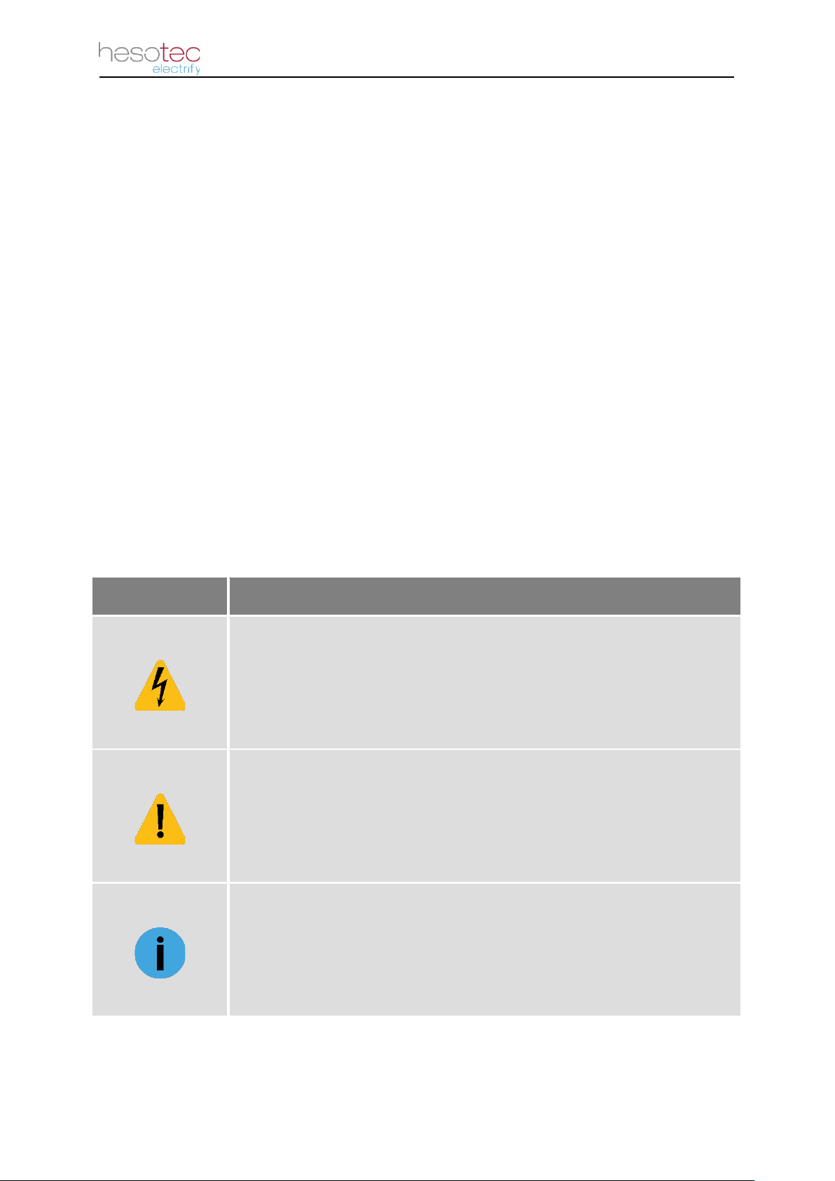
Mark Meaning
DANGER !
Safety note on a hazard with electrical voltage
Non-observance of the instructions may result in electrical damage to the
device itself, serious injury, and death.
ATTENTION !
Safety information on a hazard
Non-
observance of the instructions may result in damage to the device
itself or other consumers. Execution with special care!
NOTE !
Important information and special features
For a successful operation, the instructions should be carried out as
needed.
Product overview and dimensions 3
2 Product overview and dimensions
In this chapter you will get an overview of product information with the necessary dimensions
for the optimal planning and preparation.
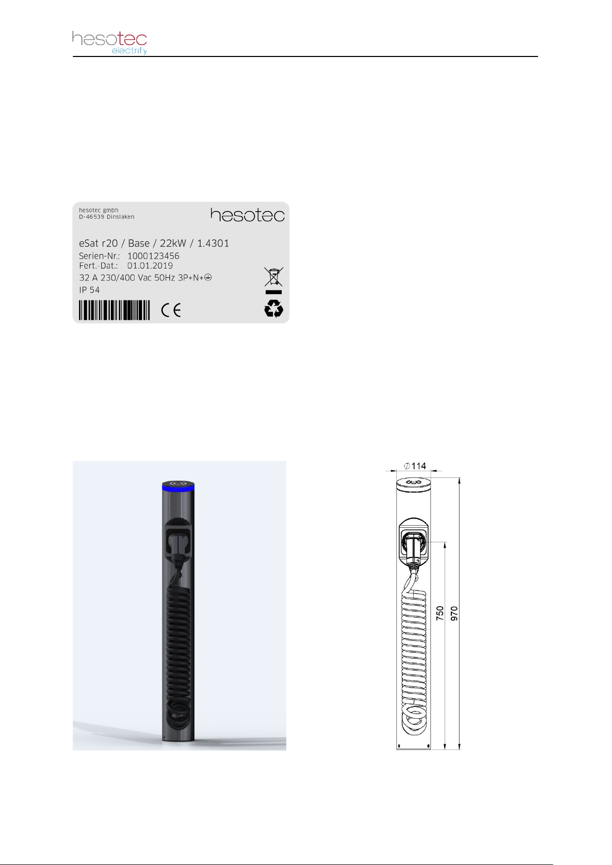
2.1 Type plate
2.2 Charging Station
The purchased electrify eSat is already fully assembled and delivered after successful
quality control. It is only a secured supply line between the house sub-distribution and the
charging station needed. The respective requirements for the power connection can be found
in the technical data.
electrify eSat r20 charging station, left: 3D model; right: dimensions (measuring unit mm)
Information on the type plate
•Manufacturer
•Series
•Model
•Power
•Serial number
•Manufacturing date
•Rated current
•Nominal voltage
•Nominal frequency
•Power supply
•Protection class

Product overview and dimensions 4
2.3 Foundation Frame (accessory) Art. 00010033
For the creation of the ground foundation for safe and stable attachment of the charging
station, hesotec electrify optionally offers a foundation frame, which is poured in with
concrete. With the help of prefabricated bolting points the assembly of the charging column is
facilitated. The height can be adjusted on request.
Top and side view of foundation frame (measuring unit mm)
Three-dimensional view of foundation frame

Product overview and dimensions 5
*) Technical data for a maximum charging power of 11 kW
**) Extension via app purchase possible
2.4 Technical Data
eSat r20 Base 11kW / 22kW
Vehicle connection (output)
1 x Charging plug Typ 2 with spiral cable 20 A* / 32 A, length about 4 m
Output voltage 230 / 400 V
Maximum charging current 16 A* / 32 A
Maximum charging power 11 kW* / 22 kW
Shutdown All poles
Components
DC fault current detection electronic, I∆n d.c. ≥6mA
Load contactor 4-pole with contact monitoring
Protection class IP54
Communication
Interface WLAN, Digital Input
Protocol eCCP
Authorization APP, RFID**
Requirement power connection
Mains connection 5 x 4 mm2* / 5 x 6 mm2
Rated voltage 230 / 400 V
Rated current 16 A* / 32 A
Safeguarding 20 A* / 32 A, 3-poles, B-characteristics
AC fault current detection RCCB, Type A, 30mA
Dimensions
Height 970 mm
Diameter 114 mm
Parkbox (height / center) 750 mm

Product overview and dimensions 6
*) Technical data for a maximum charging power of 11 kW
**) Extension via app purchase possible
eSat r20 Smart 11kW / 22kW
Vehicle connection (output)
1 x Charging plug Typ 2 with spiral cable 20 A* / 32 A, length about 4 m
Output voltage 230 / 400 V
Maximum charging current 16 A* / 32 A
Maximum charging power 11 kW* / 22 kW
Shutdown All poles
Components
DC fault current detection electronic, I∆n d.c. ≥6mA
Load contactor 4-pole with contact monitoring
Protection class IP54
Energy meter Type PX EEM 357
Communication
Interface WLAN, LAN, Digital Input
Protocol eCCP, OCCP 1.6J**
Authorization APP, RFID
Management APP statistics, Chargemanagementsystem (eLMS)
Requirement power connection
Mains connection 5 x 4 mm2* / 5 x 6 mm2
Rated voltage 230 / 400 V
Rated current 16 A* / 32 A
Safeguarding 20 A* / 32 A, 3-poles, B-characteristics
AC fault current detection RCCB, Type A, 30mA
Dimensions
Height 970 mm
Diameter 114 mm
Parkbox (height / center) 750 mm

Installation 7
3 Installation
3.1 Demands on Location of Charging Stations Location
DANGER !
Safety note on a hazard with electrical voltage
Pay attention to a proper installation. Non-observance of the require-
ments leads to a danger with electric voltage.
The electrify eSat charging station is for outdoor and indoor use designed. For the installation
of the loading unit, regulations regarding the location of installation must be ensured. Only in
this way safe operation can be guaranteed.
The following requirements must be met:
•No instillation in vulnerable areas with a high risk of flooding.
•No instillation in vulnerable areas with a risk of explosion.
•Enough distance to other technical equipment.
•Select installation location so that the charging station can be reached easily with the
parked vehicle (charging cable must not be strained during charging operation!).
•No direct spray water.
•Ambient temperature between -25 °C and 45 °C (-13°F and 113°F).
•For installation of low-voltage systems, the specifications IEC 60364-1 and
IEC 60364-5-52 must complied.
•In order to withstand mechanical stresses, the mounting surface must be designed
with sufficient strength.
•Make sure that the power supply is sufficiently dimensioned. Note that the sizing
does not exceed the slot of the cable routing of the socket. (Information on power
connection: see technical data)
NOTE !
Important information and special features
Avoid a confusing installation location to prevent unnecessary damage to
the charging station.
While selecting the location of the charging station, remember to avoid a possible knock
down of the charging station. If necessary, set up a collision protection. Also avoid placement
near entry and exit points. Set up the charging station so that the use of rescue vehicles is
not restricted.
Installation 8
3.2 Creation of the Charging Stations Foundation
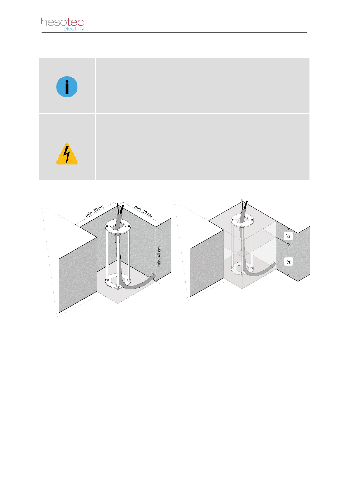
NOTE !
Important information and special features
For safe and stable mounting of the charging station, we recommend the
accessory "Foundation Frame" by hesotec electrify.
DANGER !
Safety note on a hazard with electrical voltage
Make sure that the supply line is de-energized at the time of the creation
of the foundation. Failure to observe the safety instructions can lead to a
risk of death due to electrical voltage.
Observe alignment of the foundation frame!
See assembly instructions for foundation
frame.
Foundation creation with accessory "foundation frame"
After digging the soil, shutter the area of the foundation. Then insert the foundation frame
and guide an empty conduit through the provided opening. To align the base frame, pay
attention to the front mark, which is located on the mounting plate. Next you can lead the
supply line through the empty conduit. Leave a sufficient length above the ground level.
Level the foundation frame, making sure the foundation plate is flush with the ground level.
Then fill the lower 2/3 of the foundation with class C30 / 25 concrete and let it set. The
remaining 1/3 should be filled with shrink-free concrete, so that the foundation plate lies
flush. After complete setting, the assembly takes place.
Installation 9
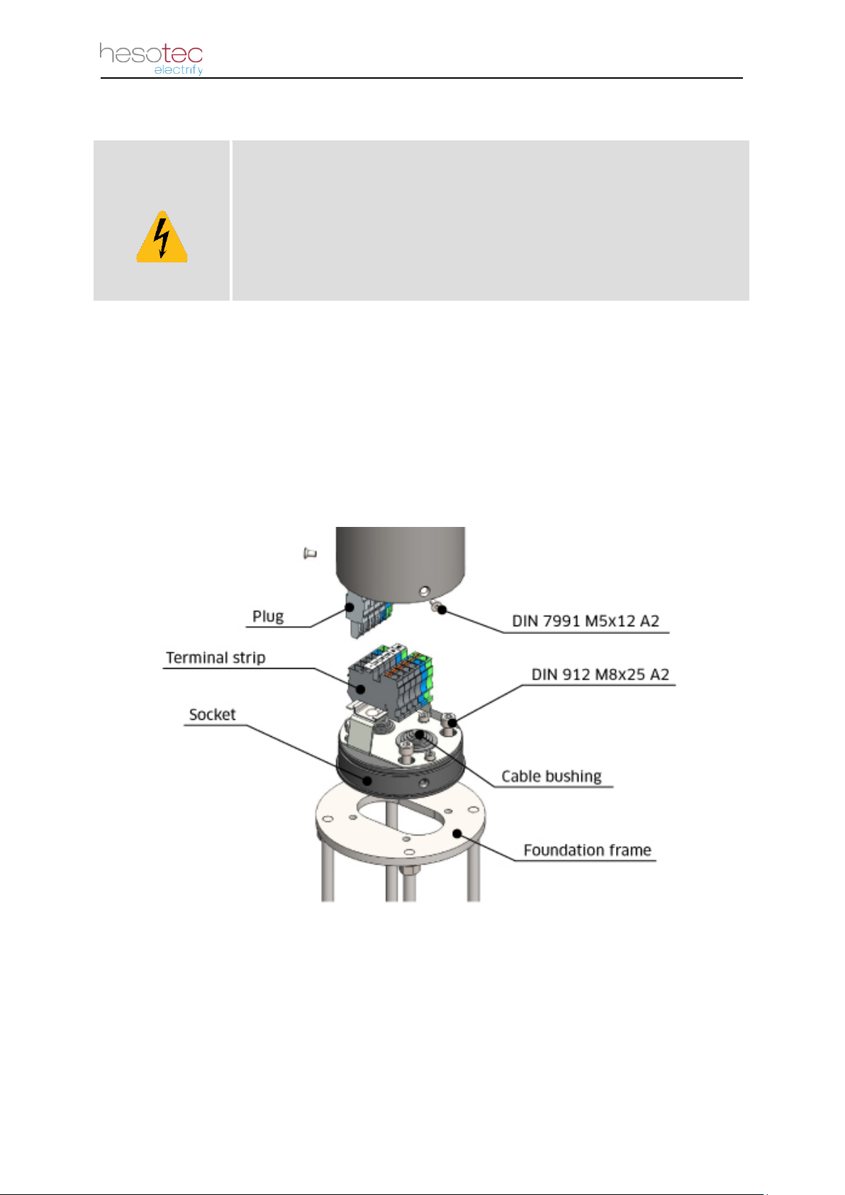
3.3 Assembly of Charging Station
DANGER !
Safety note on a hazard with electrical voltage
Make sure that the supply line is de-energized at the time of installation.
Failure to observe the safety instructions can lead to a risk of death due
to electrical voltage.
The electrify charging station eSat should only be installed by qualified personnel. Please
refer to the respective subchapters for the respective assembly steps. Make sure that the
supply line is de-energized at the time of the assembly!
3.3.1 Assembly with Montage with accessory “Foundation Frame”
The electrify charging station eSat is already pre-assembled in the factory. To assemble the
charging station, in combination with the accessory "foundation frame", proceed as follows:
Installation in combination with foundation frame
1. First loosen the 3 side screws at the lower end of the charging station.
(similar to DIN 7991 M5x12 A2)
2. Then gently pull the black socket out of the charging station.

Installation 10
3. Feed the supply cable through the cable gland of the base and screw the base to the
foundation frame, which has already been set in concrete, using the screws supplied.
(DIN 912 M8x25 A2)
4. Before screwing the charging station to the base, read the chapter "3.4.1 Electric in-
stallation of the Charging Station".
5. After the successful electrical installation, place the charging post on the base and
screw it with the 3 lateral screws. (similar to DIN 7991 M5x12 A2)
3.3.2 Assembly on an alternative Ground
The electrify charging station eSat is already preassembled in the factory. To install the
charging station on an alternative ground, proceed as follows:
Installation on alternative ground
1. First loosen the 3 side screws at the lower end of the charging station.
(similar to DIN 7991 M5x12 A2)
2. Then gently pull the black socket out of the charging station.
3. Place the base on the existing foundation and adjust it
4. Mark the mounting points of the base on the foundation.

Installation 11
5. Drill the previously marked holes (ø 10 mm). Use the included mounting kit for
mounting. Make sure that the fixing dowels are sunk into the foundation and do not
protrude above.
6. Feed the supply cable through the cable gland of the base and screw the base with
the screws provided. (DIN 912 M8x25 A2)
7. Before screwing the charging station to the base, read the chapter "3.4.1 Electric
installation of the Charging Station".
8. After the successful electrical installation, place the charging post on the base and
screw it with the 3 lateral screws. (similar to DIN 7991 M5x12 A2)
ATTENTION !
Safety information on a hazard
Make sure that the ground foundation has sufficient strength. Failure to
follow the instructions may result in damage to the device itself or to oth-
er consumers.

Installation 12
3.4 Electrical Installation
DANGER !
Safety note on a hazard with electrical voltage
Make sure that the cables are de-
energized at the time of installation.
Failure to follow the instructions may result in a risk of death due to elec-
trical voltage.
ATTENTION !
Safety information on a hazard
Failure to follow the instructions may result in damage to the device itself
or other consumers. Execution with special care!
The electrical installation of the charging station may only be carried out by qualified
personnel. When installing the electrical system, make sure that the cables are not damaged
or crushed. These could interfere with the functions in later use, cause defects or even cause
a fire.
The following table shows the connection diagram of the connection point between the
ground side supply line and the charging unit cables including the functional description.
Supply Line Ground
Terminal
Strip
Loading Unit
Color
Function
Label
Color
Function
- - LR black
Phase for power sup-
ply / charge controller
brown Phase 1 L1 brown Phase 1
black Phase 2 L2 black Phase 2
grey Phase 3 L3 grey Phase 3
blue Neutral conductor N blue Neutral conductor
green/yellow Protective conductor PE green/yellow Protective conductor
Connection diagram terminal strip electrify eSat r20
NOTE !
Important information and special features
Please take the requirements of the power connection from the technical
data sheet in chapter 2.4.
Installation 13
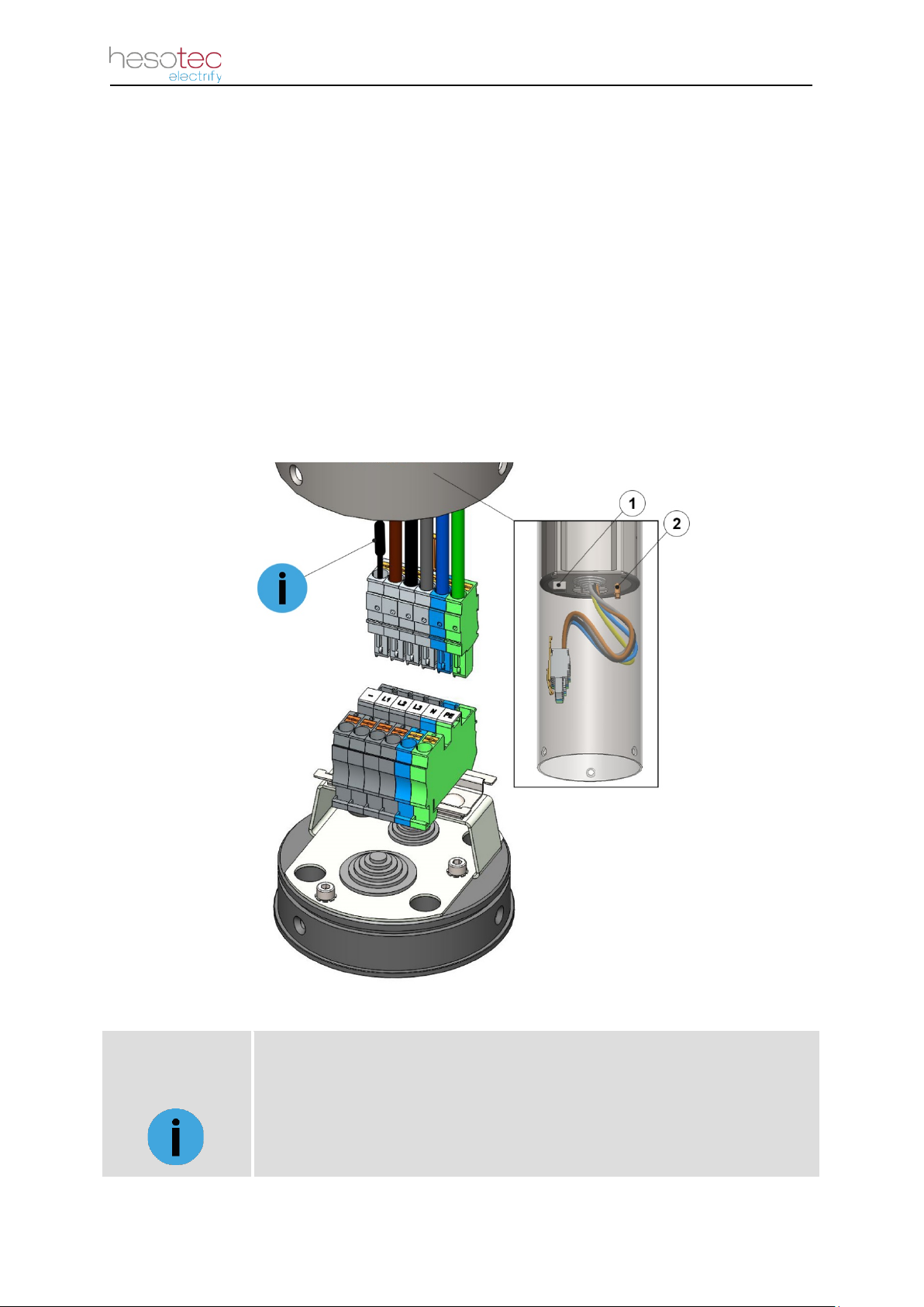
3.4.1 Electrical Installation of the Charging Station
The electrify eSat charging station is already preassembled in the factory and wired electron-
ically. All you have to do is connect the supply line to the connection socket.
For the electrical installation of the charging station, proceed as follows:
1. Connect the 5-wire cable coming from the ground to the terminal strip according to
the terminal label. (L1, L2, L3, N, PE)
2. Insert the plug coming in from the charging station into the terminal strip.
Note: Depending on the equipment, the LAN connection (item 1) is in the
Charging column (see data sheet in chapter 2.4.). Digital inputs (item 2).
Wiring the electrify eSat charging station
NOTE !
Important information and special features
The cable LR of the 22kW version is provided with a fuse (G-
fuse link
5X20mm 10A).
Installation 14
ATTENTION!
Safety notice of a hazard
The electrical installation of the digital inputs may
only be carried out by qualified specialist personnel.
ATTENTION!
Safety notice of a danger
The digital inputs are connected with an
external 12V dc power supply.
Failure to observe the voltage will damage
the device.
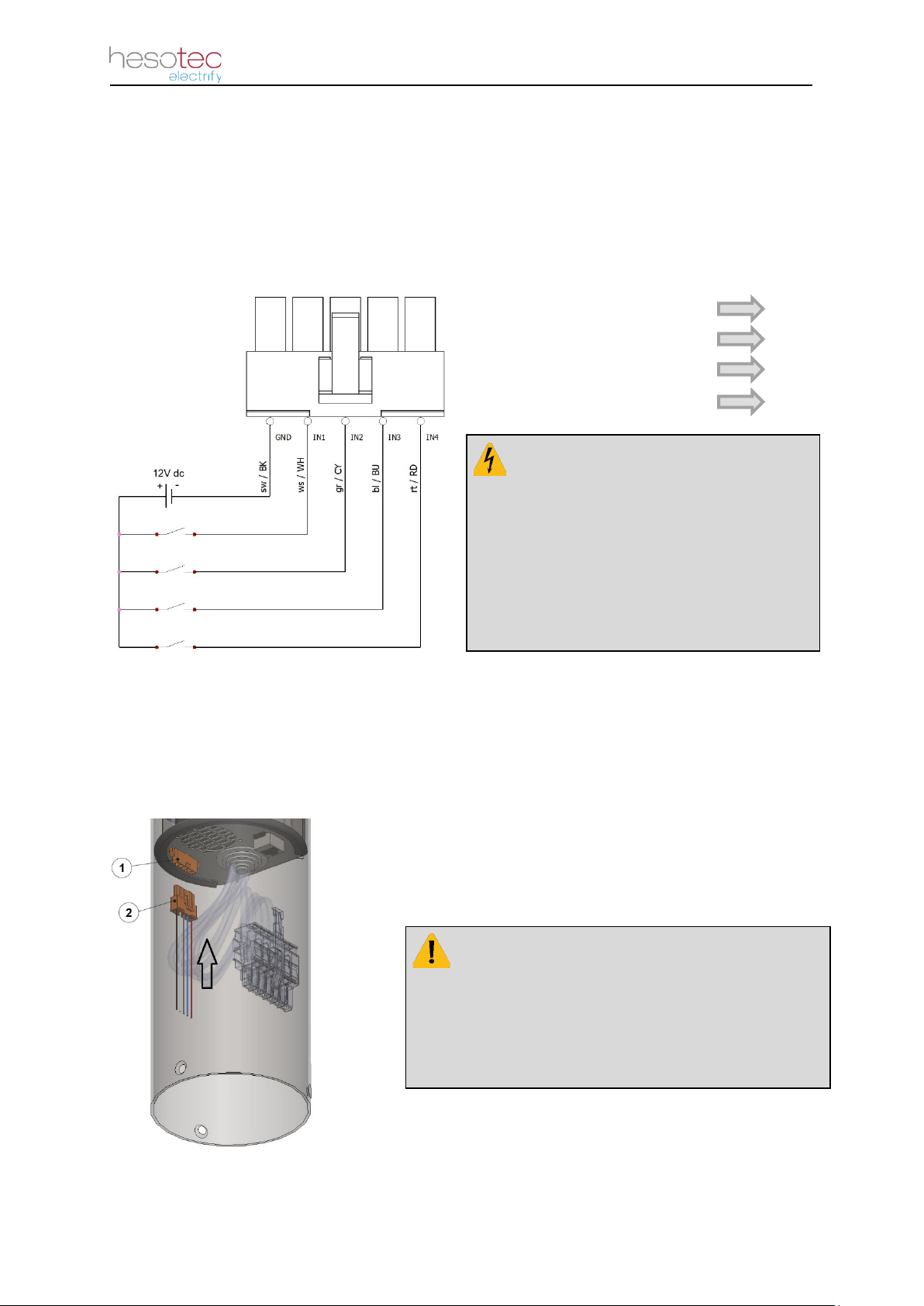
3.4.2 Connection of the digital inputs
The electrify eSat charging unit is equipped with an interface for digital inputs. With the digital
inputs, you have the option of reducing the charging power to 75%, 50%, 25% or issuing an
external charging release. The wiring of the individual inputs is shown in the graphic
below.
Connection drawing of the digital inputs
To use the digital inputs, use the cable adapter included in the scope of delivery. The
installation location is shown in the following illustration.
Plug connection of the digital inputs
1. Connector for digital input
2. Cable adapter for digital input
•External charge release IN1
•Charging power 75% IN2
•Charging power 50% IN3
•Charging power 25% IN4

Operation 15
Green Blue White Red
Yellow Orange Pink Purple
4 Operation
Your electrify charging station is delivered preconfigured at the factory. With the help of the
electrify Charge Control App (eCC) or the electrify Charge Management System (eLMS) you
can make further settings and evaluations.
4.1 Control Element
The following graphic shows the main operating elements of the electrify eSat r20 charging
station:
Operating elements of the electrify Charging Station eSat
4.2 LED indicator
The electrify eSat signals the respective operating status with the aid of the LED indicator.
With the electrify charge control app, the user can choose between 8 colours.
1. RFID – Card Reader
2. LED indicator
3. Charging Cable
Operation 16
Green
Blue
Blue
White
Red
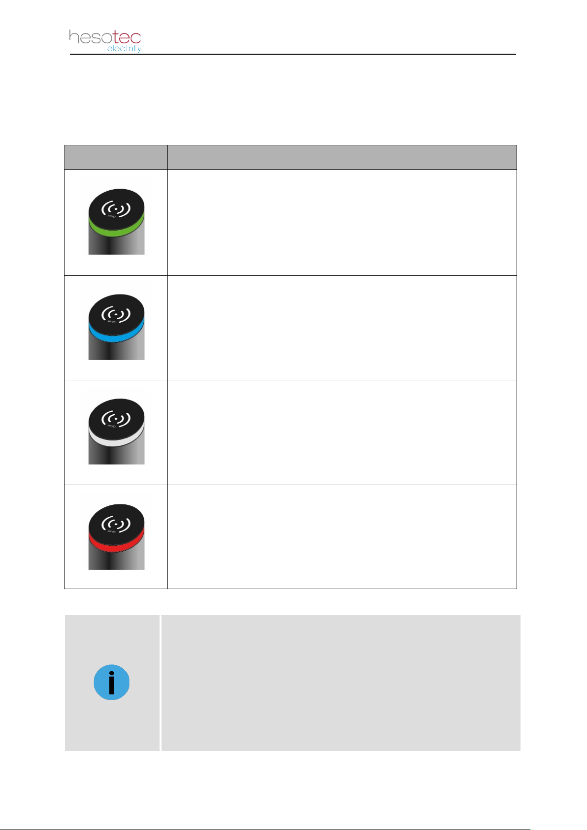
The electrify eSat charging station is preconfigured with a color combination to indicate the
operating status. The default color scheme, with the associated operating status, is shown in
the following table:
Graphic Operating Status
State A: Charging Station is ready for operation.
State B: Electric vehicle is plugged in.
State C: Charging is active (pulsating).
Wait for authorization via app or RFID card.
State E: There is a fault at the charging station.
NOTE !
Important information and special features
The color scheme
is configured with the electrify Charge Control app.
Not only the color but also the dynamics can be adjusted.
(Light permanent or pulsating)
For more information, see the Quick Guide of the electrify app.
Operation 17
4.3 Charging Process
The charging process of the electrify charging stations is the same for all product variants.
No matter if you decide for the base, smart or other. Only the approval of the charging pro-
cess is different among each other.
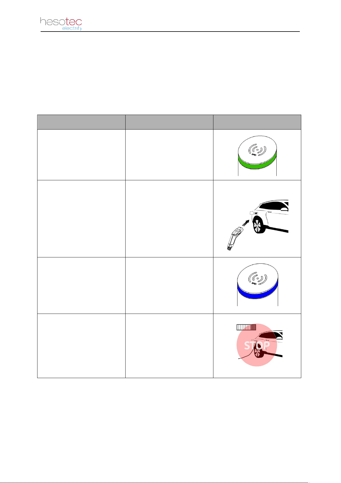
4.3.1 Charging station without authorization (Plug and Charge)
Process Step Information Graphic
1.
First check the operating
status of the eSat charging
station.
eSat charging station is
ready for operation with
green LED indicator.
2. Connect the charging plug
to the vehicle to be charged.
After the charging plug is
successfully connected to
the vehicle, the locking takes
place. Further information
can be found in the operating
instructions of the vehicle.
3. Charging is started. After a successful authoriza-
tion, the loading process is
released. The LED indicator
lights up blue.
4.
End charging process
prematurely.
The charging process can be
stopped via the vehicle. The
latter is taken from the
operating instructions of the
vehicle
Table of contents
Other hesotec electrify Batteries Charger manuals


Popular Batteries Charger manuals by other brands


Chargery Power
Chargery Power 550B operating instructions

MS
MS -400C series user manual

Charging Systems International
Charging Systems International Dual Pro SE Xtreme Installation and operating instructions

Berner
Berner BACC-36V LI operating instructions

Helvi
Helvi EXPLORER 120 operating manual

multicomp pro
multicomp pro PD3.0 user manual


