manuals.online logo
Brands
  1. Home
  2. •
  3. Brands
  4. •
  5. Hessaire
  6. •
  7. Fan
  8. •
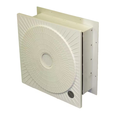
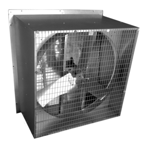
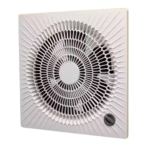
  9. Hessaire 8SF User manual

Hessaire 8SF User manual

man_SF_Online_EN_ 072323 www.hessaire.com
Please read and save these instructions. Read carefully before attempting
to install, operate or maintain the equipment described within this manual.
Carefully follow all safety information.
Save this manual for future reference.
Model # ___________________________ Purchase Date:______________
Shutter Mounted Exhaust Fan Manual
Thermostat Included With Select Models
Sizes: 8” - 36” • 115V/60HZ • UL/cUL 705
Models Covered—Without Thermostat
8SF, 10SF, 12SF, 12SF4T50C, 14SF,
16SF, 16SF4T60C, 18SF, 18SF180,
20SF, 20SF4T90C, 24SF, 24SF240,
24SF6D240C, 30SF8N240, 36SF8N370
Index
General Safety / Installation…………………………………………………….……2
Specifications / Thermostat………………..…………….……………….…………..3
Parts / Maintenance / Troubleshooting……………….…………………….……….4
Models Covered—Thermostat Included
8SF-TH, 10SF-TH, 12SF-TH, 14SF-TH,
16SF-TH, 18SF-TH, 20SF-TH, 24SF-TH
Tools/Materials Needed:
• Drill/drill bits
• Ratchet/Socket set
• Mounting Fasteners
Contents:
• Exhaust Fan (1)
• Instruction Manual (1)
+
General Safety Instructions
Warning:
Before installing or servicing, disconnect all power. Keep hands and body parts
clear of all moving parts when installing or servicing.
Read and follow all instructions, cautions and warnings. Failure to do so could result in
personal injury, death or property damage.
Electrical connections, installation and maintenance must be done by qualified
personnel in accordance with all applicable codes. Unit must be adequately grounded.
To reduce the risk of fire or electrical shock, do not expose this fan to water or touch
electrically live components.
Free rotation of the propeller is critical. It must not touch any part of the guard, shutter,
or opening framework.
Ensure that all power cords do not come in contact with any sharp edges, hot surfaces
or chemicals. Immediately replace any damaged cords.
Keep hands and body parts clear of all moving parts when installing or servicing.
Inspection
Fan Installation & Operation Tips
After unpacking your fan, carefully inspect for any damage that may have occurred
during transit. Inspect for loose, missing or damaged parts. If there is physical damage
to any parts of the fan, a freight claim must be filed with the carrier. Check to make
sure that all bolts, screws and set screws are securely tightened and have not become
loose during transit. Retighten as required.
Caution: Before operating your new fan, check blade for proper torque,
check all fasteners for tightness. Ensure fan blade is not obstructed.
For exhaust opening dimensions, refer to rough-in opening dimensions shown in the
specifications table in this manual.
Position the fan for desired airflow. Refer to fan mounting orientation in this manual.
Ensure the fan is fastened securely to the wall to avoid excess “rattling” or vibration.
Fasteners not included.
Refer to motor nameplate for wiring diagram.
Ensure that the area in front of and behind the fan is clear of any objects that may inter-
fere with airflow.
Shutter louvers must open and close freely.
Adequate intake air must be available to the fan for proper exhausting of air.
Check for excessive vibration while fan is running. If excessive vibration is noticed,
refer to troubleshooting chart in this manual.
When using speed controls on the variable speed capable models, it is recommended
to operate at no less than 50% of line voltage. Controls sold separately.
Variable speed controls should be installed by a qualified electrician.
“-TH” models include thermostat.
man_SF_Online_EN_ 072323 www.hessaire.com
Performance/Specifications (Models Without Thermostat)
Wall Mount Junction Box
Extendable Temperature
Probe Up to 48”
Performance/Specifications (Models Including Thermostat)
Thermostat
Model: TH120C
Rough-In Dims.
Wiring
Diagram
Black (line)
White (common)
Green (ground)
Motor
Thermostat
Control
Incoming
Power
Black
P1
120 VAC
Variable Speed Capable Models DO NOT include control. Variable speed control sold separately.
A
2 1
Model:
High
CFM
Area
Cov.
Sq Ft
Prop
Dia. HP Ph Volts High
Amps Spd
Rough-In
Opening
Dim. A
Dim.
B
In.
Dim.
C
In.
Dim.
D
In.
Dim.
E
In.
8SF 300 150 8” 1/25 1 115 .6 Var. Cap. 8.5 5.7 6.0 8.0 11.0
10SF 650 200 10” 1/25 1 115 .6 Var. Cap. 10.5 5.7 6.0 10.0 13.0
12SF 900 250 12” 1/15 1 115 1.0 Var. Cap. 12.5 5.7 6.0 12.0 15.0
12SF4T50C 1100 300 12” 1/12 1 115 1.0 3 12.5 5.7 6.0 12.0 15.0
14SF 1350 325 14” 1/10 1 115 1.1 Var. Cap. 14.5 5.7 7.0 14.0 17.0
16SF 1400 350 16” 1/10 1 115 1.1 Var. Cap. 16.5 5.7 7.0 16.0 19.0
16SF4T60C 1325 325 16” 1/12 1 115 1.1 3 16.5 5.7 6.0 16.0 19.0
18SF 1785 400 18” 1/10 1 115 1.1 Var. Cap. 18.5 5.7 7.0 18.0 21.0
18SF180 3130 800 18” 1/4 1 115 2.8 Var. Cap. 18.5 5.7 11.0 18.0 21.0
20SF 3340 900 20” 1/4 1 115 2.8 Var. Cap. 20.5 5.7 11.0 20.0 23.0
20SF4T90C 2860 775 20” 1/8 1 115 1.3 3 20.5 5.7 7.0 20.0 23.0
24SF 4160 1100 24” 1/3 1 115 3.0 Var. Cap. 24.5 5.7 12.0 24.0 27.0
24SF240 4450 1300 24” 1/3 1 115 3.2 Var. Cap. 24.5 5.7 12.0 24.0 27.0
24SF6D240C 4450 1300 24” 1/3 1 115 3.2 2 24.5 5.7 12.0 24.0 27.0
30SF8N240 5895 1750 30” 1/3 1 115 3.8 1 30.5 5.7 12.0 30.0 33.0
36SF8N370 8860 2200 36” 1/2 1 115 5.6 1 36.5 5.7 13.0 36.0 39.0
Model:
Thermostat
Included
High
CFM
Area
Cov.
Sq Ft
Prop
Dia. HP Ph Volts High
Amps
Thermostat Rough-In
Opening
Dim. A
Dim.
B
In.
Dim.
C
In.
Dim.
D
In.
Dim.
E
In.
Electrical
Rating
Probe
Length
In.
8SF-TH 300 150 8” 1/25 1 115 .6 16A 400V 48 8.5 5.7 6.0 8.0 11.0
10SF-TH 650 200 10” 1/25 1 115 .6 16A 400V 48 10.5 5.7 6.0 10.0 13.0
12SF-TH 900 250 12” 1/15 1 115 1.0 16A 400V 48 12.5 5.7 6.0 12.0 15.0
14SF-TH 1350 325 14” 1/10 1 115 1.0 16A 400V 48 14.5 5.7 7.0 14.0 17.0
16SF-TH 1400 350 16” 1/10 1 115 1.0 16A 400V 48 16.5 5.7 7.0 16.0 19.0
18SF-TH 1785 400 18” 1/10 1 115 1.0 16A 400V 48 18.5 5.7 7.0 18.0 21.0
20SF-TH 3340 900 20” 1/4 1 115 2.8 16A 400V 48 20.5 5.7 11.0 20.0 23.0
24SF-TH 4160 1100 24” 1/3 1 115 3.2 16A 400V 48 24.5 5.7 12.0 24.0 27.0
A
D
D
C
E
E
B
Exterior
Rough-In
Opening
Interior
Troubleshooting Guide
Propeller
Motor
Guard
Model: Prop Guard Motor Shutter
8SF 9001655 G7SF E030-4 S7SF
10SF 9001656 G10SF E030-4 S10SF
12SF 9001657 G12SF E035-4 S12SF
12SF4T50C 9001694 G12SF E060-43C S12SF
14SF 9001695 G14SF E075-4 S14SF
16SF 9001658 G16SF E075-4 S16SF
16SF4T60C 9001696 G16SF E060-43C S16SF
18SF 9001959 G18SF E075-6 S18SF
18SF180 9001660 G12SF B180-4 S18SF
20SF 9001652 G20SF B180-4 S20SF
20SF4T90C 9001494 G20SF E090-43C S20SF
24SF 9001665 G24SF B180-6 S24SF
24SF240 9001664 G24SF B240-6 S24SF
24SF6D240 9001664 G24SF B240-6/2 S24SF
30SF8N240 9001666 G30SF B250-8F S30SF
36SF8N370 9001667 G36SF B370-8F S36SF
Model: Prop Guard Motor ThermostatShutter
8SF-TH 9001655 G7SF E030-4 TH120CS7SF
10SF-TH 9001656 G10SF E030-4 TH120CS10SF
12SF-TH 9001657 G12SF E035-4 TH120CS12SF
14SF-TH 9001695 G14SF E075-4 TH120CS14SF
16SF-TH 9001658 G16SF E075-4 TH120CS16SF
18SF-TH 9001959 G18SF E075-6 TH120CS18SF
20SF-TH 9001652 G20SF B180-4 TH120CS20SF
24SF-TH 9001665 G24SF B180-6 TH120CS24SF
Periodic maintenance and component cleaning schedules should be set to assure
reliability and performance of the fan.
Periodically inspect and tighten all set screws and hardware—check torque on prop.
Assure all mounting hardware remains properly secured.
Motors feature permanently sealed ball bearings and require no further lubrication.
Note: Please contact the dealer/distributor where you purchased the fan from
with any questions regarding the fan, the manual or replacement parts.
Maintenance
Replacement Parts Breakdown
Thermostat
Symptom Possible Cause(s) Corrective Action
Fan will not start
1. Tripped circuit breaker 1. Reset circuit breaker
2. Defective motor 2. Repair or replace
3. Incorrectly wired 3. Shut off power, check for proper connections
4. Electricity turned off 4. Contact local power company
Excessive noise or
vibration
1. Propeller is bent or hitting housing 1. Free propeller of obstruction/replace propeller
2. Fan / shutter not securely anchored 2. Secure properly
3. Bad/noisy bearings 3. Replace motor
Insufficient airflow
1. Incorrect voltage applied 1. Wire properly
2. Defective motor 2. Replace motor
3. Propeller is damaged 3. Replace propeller
4. Blocked Airflow 4. Remove obstructions
5. Not enough intake air 5. Add additional air intake openings
6. Fan is dirty 6. Clean fan guards/screens, motor and propeller
Motor overheats or trips
out
1. Over/under line voltage 1. Contact local power company
2. Defective motor 2. Replace motor
3. Fan is dirty 3. Clean fan guards/screens, motor and propeller
4. Not enough intake air 4. Add additional air intake openings
Shutter

This manual suits for next models

23

Other Hessaire Fan manuals

Hessaire MC61M User manual

Hessaire

Hessaire MC61M User manual

Hessaire ES14 User manual

Hessaire

Hessaire ES14 User manual

Hessaire S8V User manual

Hessaire

Hessaire S8V User manual

Hessaire EC14 User manual

Hessaire

Hessaire EC14 User manual

Hessaire 36SW550 User manual

Hessaire

Hessaire 36SW550 User manual

Hessaire 8GM User manual

Hessaire

Hessaire 8GM User manual

Hessaire 36D370S User manual

Hessaire

Hessaire 36D370S User manual

Hessaire 36DSW370-N User manual

Hessaire

Hessaire 36DSW370-N User manual

Hessaire 36DSW370 User manual

Hessaire

Hessaire 36DSW370 User manual

Hessaire 24D370 User manual

Hessaire

Hessaire 24D370 User manual

Popular Fan manuals by other brands

Luminance Brands kathy ireland HOME Summerhaven LED... owner's manual

Luminance Brands

Luminance Brands kathy ireland HOME Summerhaven LED... owner's manual

Home Decorators Collection NORTHAMPTON AM592-EB Use and care guide

Home Decorators Collection

Home Decorators Collection NORTHAMPTON AM592-EB Use and care guide

TroposAir 3LA44 owner's manual

TroposAir

TroposAir 3LA44 owner's manual

Lenoxx MF550 quick start guide

Lenoxx

Lenoxx MF550 quick start guide

Progress Lighting AirPro P2544-2030K installation manual

Progress Lighting

Progress Lighting AirPro P2544-2030K installation manual

Dhom Teck Systems FS-40M User and Maintenance

Dhom Teck Systems

Dhom Teck Systems FS-40M User and Maintenance

HJM VT560 instructions

HJM

HJM VT560 instructions

Mitsubishi Electric TRANE CITY MULTI Series Service manual

Mitsubishi Electric

Mitsubishi Electric TRANE CITY MULTI Series Service manual

ICE AIR FCHC Operating and maintenance manual

ICE AIR

ICE AIR FCHC Operating and maintenance manual

SODECA CBDT 9/9-4T user manual

SODECA

SODECA CBDT 9/9-4T user manual

COOK SQN Series Installation, operation and maintenance manual

COOK

COOK SQN Series Installation, operation and maintenance manual

Elicent EXT Series instruction manual

Elicent

Elicent EXT Series instruction manual

Holmes HT38 owner's guide

Holmes

Holmes HT38 owner's guide

Mistral MTF-D5070 instruction manual

Mistral

Mistral MTF-D5070 instruction manual

FUAVE TV3010 instruction manual

FUAVE

FUAVE TV3010 instruction manual

Modine Manufacturing MPR Installation and service manual

Modine Manufacturing

Modine Manufacturing MPR Installation and service manual

Create WIND PROP user manual

Create

Create WIND PROP user manual

Panasonic F-M14C8 Operating and installation instructions

Panasonic

Panasonic F-M14C8 Operating and installation instructions

manuals.online logo
manuals.online logoBrands
  • About & Mission
  • Contact us
  • Privacy Policy
  • Terms and Conditions

Copyright 2025 Manuals.Online. All Rights Reserved.