Hestia MIRAGE User manual

ASSEMBLY
INSTRUCTIONS
MIRAGE
ASSEMBLY INSTRUCTIONS
Made in EnglandMade in England
1. Unpack in the room the bed is
intended to be used, remove all
packaging and dispose of carefully,
keeping polythene out of the reach
of children.
Introduction
and components
This is a two person assembly.
Do not attempt to install by
yourself as it could result in injury.
WARNING The following tools are required
for this assembly
1 x Hammer
Tools required
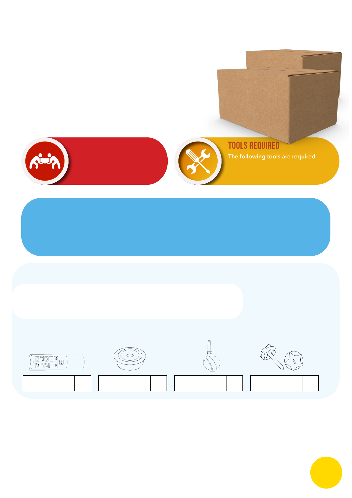
CONTENTS:
• 8 X Plastic Spacer Washers
• 8 X Plastic Head Bolts
• 1 X Motor
• 1 X Handset (82418)
• 8 X Silver Ball Castors
Please check the pack contents before attempting
to assemble this product.
If any components are missing, please contact the retailer
from whom you bought this product.
FIXING - HBWASHER
= x8
FIXING M8 HB BOLTS
= x8 (4 for middle join)
RF HANDSET
= x1
SILVER CASTOR
50mm= x8
CHECK LIST - BED ASSEMBLY
MIRAGE MEMORY
PACKING BAG
Assembly Instructions,
Guarantee and Care Guide
Salisbury, Mirage & Independent
ADIVISION OF
Furmanac
furmanac.com
m o t i o n
LEAFLET-HESTIA-MOTION-ASSEMBLY = x1
CASTOR-SILVER-50MM-SHEP-ME = x8
FIXING-M8HBWASHER = x8
FIXING-M8HBBOLTS-50 = x8
(4 for middle join)
M1 M2
MOTOR-OKIN-82418
This product is HEAVY, it should be assembled as near as possible to the point of use.
TAKE CARE WHEN LIFTING to avoid personal injury and (or) damage to the product.
This product takes approximately 40 MINUTES to assemble with 2 PEOPLE.
The ttings pack contains SMALL ITEMS which should be KEPT AWAY FROM YOUNG CHILDREN.
Read this leaet in full before commencing assembly. 2

3
In the room the bed is intended to be used, remove all packaging and dispose of carefully,
keeping all polythene and cable es out of the reach of children.
Base
Foot End Head End
Mirage Manual:Layout 1 6/23/2015 10:39 AM Page 3
4
●Li the two ends onto their sides.
●Push the two ends together.
Using 4 x Plasc-headed bolts (A),
thread the bolts into the 4 holes.
Ensure the bolts are ghtly fied.
Mirage Manual:Layout 1 6/23/2015 10:39 AM Page 4
4
●Li the two ends onto their sides.
●Push the two ends together.
Using 4 x Plasc-headed bolts (A),
thread the bolts into the 4 holes.
Ensure the bolts are ghtly fied.
Mirage Manual:Layout 1 6/23/2015 10:39 AM Page 4
Foot End Head End
2. Lift the ends onto their sides.
3. Push the two ends together.
Using the 4 X Plastic headed bolts,
thread each one into the four holes.
Ensure that the bolts are tightly tted.
This stage requires two people,
please do not attempt on your
own - as this will result in injury.
CAUTION
3
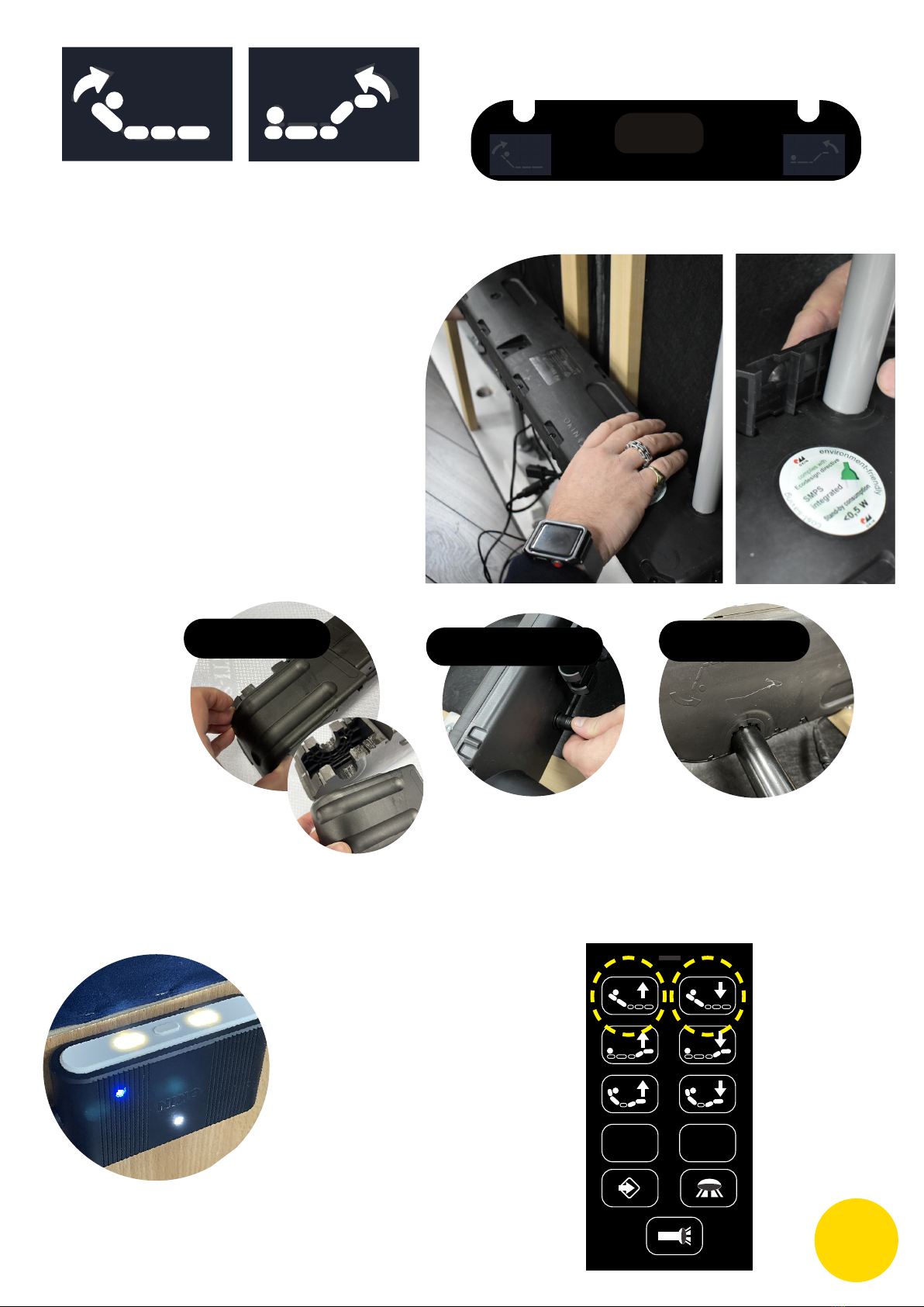
12. Attach the motor to the bed.
Identify the head and foot sides of
the motor by the images on each end
of the motor.
• Ensure your motor is the correct
way up, please use the highlighted
icons as your guide.
• Slide the caps off each side
of the motor.
• Place the motor on to the cross
bars until you hear it “click” into
position.
• Slide the caps back on to the
motor.
• Connect the Battery
(this is a safety back-up)
HEAD FOOT
Slide off covers Click onto bar Connect battery
Plug controler to
socket on motor
MOTOR-OKIN-88802 ON SURFACE
MOTOR-OKIN-92391 ON SPIRIT
Connect USB power
unit plug
4.
12. Attach the motor to the bed.
Identify the head and foot sides of
the motor by the images on each end
of the motor.
• Ensure your motor is the correct
way up, please use the highlighted
icons as your guide.
• Slide the caps off each side
of the motor.
• Place the motor on to the cross
bars until you hear it “click” into
position.
• Slide the caps back on to the
motor.
• Connect the Battery
(this is a safety back-up)
HEAD FOOT
Slide off covers Click onto bar Connect battery
Plug controler to
socket on motor
MOTOR-OKIN-88802 ON SURFACE
MOTOR-OKIN-92391 ON SPIRIT
Connect USB power
unit plug
4
12. Attach the motor to the bed.
Identify the head and foot sides of
the motor by the images on each end
of the motor.
• Ensure your motor is the correct
way up, please use the highlighted
icons as your guide.
• Slide the caps off each side
of the motor.
• Place the motor on to the cross
bars until you hear it “click” into
position.
• Slide the caps back on to the
motor.
• Connect the Battery
(this is a safety back-up)
HEAD FOOT
Slide off covers
Click onto bar Connect battery
Plug controler to
socket on motor
MOTOR-OKIN-88802 ON SURFACE
MOTOR-OKIN-92391 ON SPIRIT
Connect USB power
unit plug
12. Attach the motor to the bed.
Identify the head and foot sides of
the motor by the images on each end
of the motor.
• Ensure your motor is the correct
way up, please use the highlighted
icons as your guide.
• Slide the caps off each side
of the motor.
• Place the motor on to the cross
bars until you hear it “click” into
position.
• Slide the caps back on to the
motor.
• Connect the Battery
(this is a safety back-up)
HEAD FOOT
Slide off covers Click onto bar Connect battery
Plug controler to
socket on motor
MOTOR-OKIN-88802 ON SURFACE
MOTOR-OKIN-92391 ON SPIRIT
Connect USB power
unit plug
5. To activate your remote - power on your bed.
M1 M2
6. Once powered
on - press the top
two buttons on your
remote
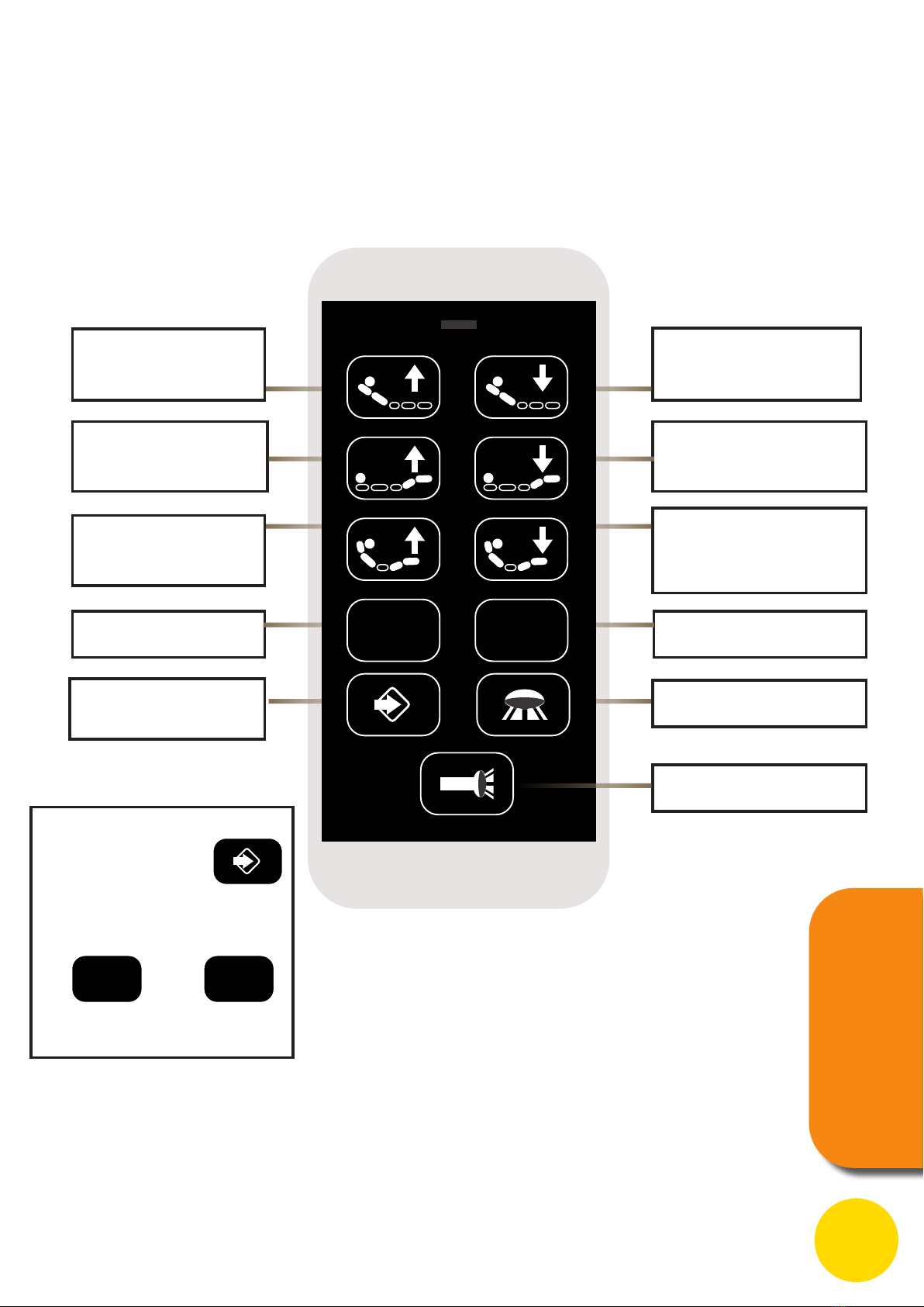
Map
of the Mirage Remote
Memory position one Memory position two
HEAD & FOOT UP button:
Press and hold the button, the Head
actuator will simultaneously go up.
Stop when released.
HEAD & FOOT DOWN
button:
Press and hold the button, the Head
actuator will simultaneously go up.
Stop when released.
FOOT UP button:
Press and hold the button,
the Foot actuator will go up.
Stop when released.
FOOT DOWN button:
Press and hold the button,
the Foot actuator will go up.
Stop when released.
HEAD UP button:
Press and hold the button,
the Head actuator will go up.
Stop when released.
HEAD DOWN button:
Press and hold the button,
the Head actuator will go up.
Stop when released.
To Store
Memory Setting
To store a memory
setting simply press
Then press the memory
button
Under Bed Light
Torch
REMOTE
INSTRUCTIONS
M1 M2
M1 M2
5
6
●Plug handset into the control box, then plug the control box cable onto the motor.
●Gently fit the 8 x Castors into the relevant sockets on the boom of the bed frame
using a hammer.
●Once fied, turn the bed over.
Repeat this process if you have a 5’ or 6’ Dual Model.
x 4x 8 x 4
Mirage Manual:Layout 1 6/23/2015 10:40 AM Page 6
6
●Plug handset into the control box, then plug the control box cable onto the motor.
●Gently fit the 8 x Castors into the relevant sockets on the boom of the bed frame
using a hammer.
●Once fied, turn the bed over.
Repeat this process if you have a 5’ or 6’ Dual Model.
x 4
x 8
x 4
Mirage Manual:Layout 1 6/23/2015 10:40 AM Page 6
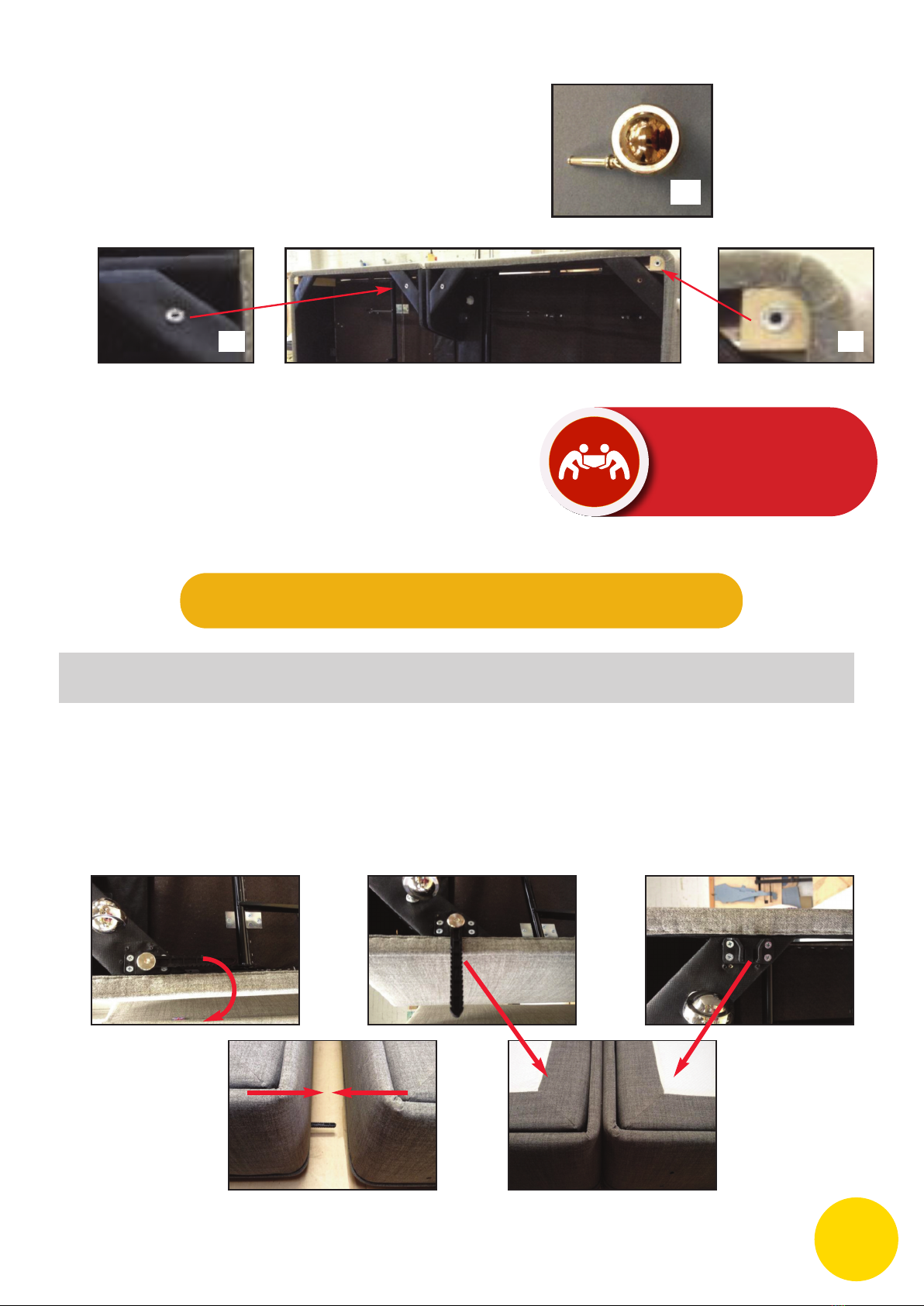
7
Fing 5’ or 6’ Dual Beds
●Assemble two base units as per previous instrucons.
●To join the beds together, on the under part of the bed, twist the bracket out.
Keeping the two base units level, push the beds together.
The brackets will meet and lock in place.
Mirage Manual:Layout 1 6/23/2015 10:40 AM Page 7
5. Gently t the 8 x Castors into the relevant
sockets on the bottom of the bed frame
using a hammer.
6. Once tted, turn the bed over onto it’s
castors.
This stage requires two people,
please do not attempt on your
own - as this will result in injury.
CAUTION
6

8
To take bases apart
●Li the one side of the bed and it will release.
Mirage Manual:Layout 1 6/23/2015 10:40 AM Page 8
9
Headboard fixing holes
2’6”, 3’ and 4’ only
5’ and 6’ Duals
Mirage Manual:Layout 1 6/23/2015 10:40 AM Page 9
BB
BB
AA
AA
7
10
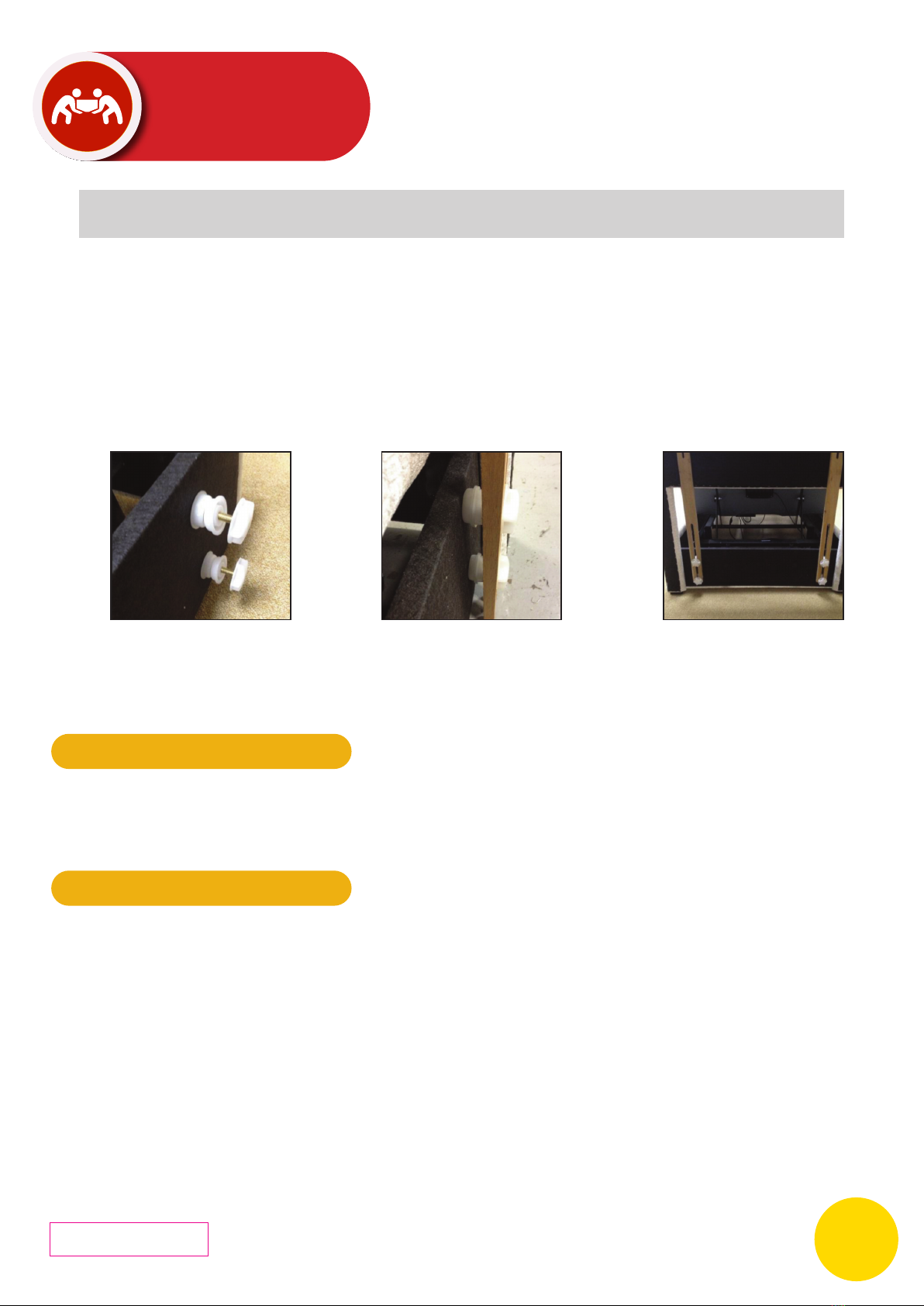
Fing the Headboard
●Using the 8 x Plasc Spacer Washers and 4 x Plasc-headed Bolts, thread two Spacers
onto the Plasc-headed Bolts as shown.
●Screw 4 of the bolts into the 4 threaded holes on the head end of the bed.
●Slide the legs of the Headboard between the Spacers and the Bolt head.
●Adjust to suitable height and ghten the 4 bolts.
●Once the maress is fied, the bed is ready for use.
Mirage Manual:Layout 1 6/23/2015 10:40 AM Page 10
11
TROUBLESHOOTING
●No power to bed: Check Mains supply / change fuse on plug or extension lead /
try different plug socket; Ensure all leads are fied correctly.
Mirage Manual:Layout 1 6/23/2015 10:40 AM Page 11
Health and Safety
●Furniture and beds with moving parts and mechanisms should be used with cauon.
Children and animals should be supervised at all mes and kept away from moving parts,
due to the possibility of entrapment.
●DO NOT allow children to play on or around the moving parts.
●Frequently inspect the electrical cables to ensure that they have not been accidentally
damaged during use.
●Always remove the mains plug when not in use.
●In the event of mechanical or electrical failure, do not aempt to open or repair the
mechanism, electrical motor or control boxes - always consult the original supplier who
can service or repair the product.
12
Mirage Manual:Layout 1 6/23/2015 10:40 AM Page 12
This stage requires two people,
please do not attempt on your
own - as this will result in injury.
CAUTION
8
VERSION 07
Correct at time of publication 9/03/22
Table of contents
Other Hestia Indoor Furnishing manuals


Popular Indoor Furnishing manuals by other brands


modway
modway Loryn MOD-5357 manual

Lightolier
Lightolier 4F28 specification

Furniture of America
Furniture of America Bellagio CM3319F-AC-2PK Assembly instructions

Hay
Hay CRATE Series instruction manual

Delta Children
Delta Children Simmons Kids Rowen Nightstand Assembly instructions

Walker Edison
Walker Edison W58BMHP2D Assembly instructions


