Technik für Möbel
www.hettich.com 3
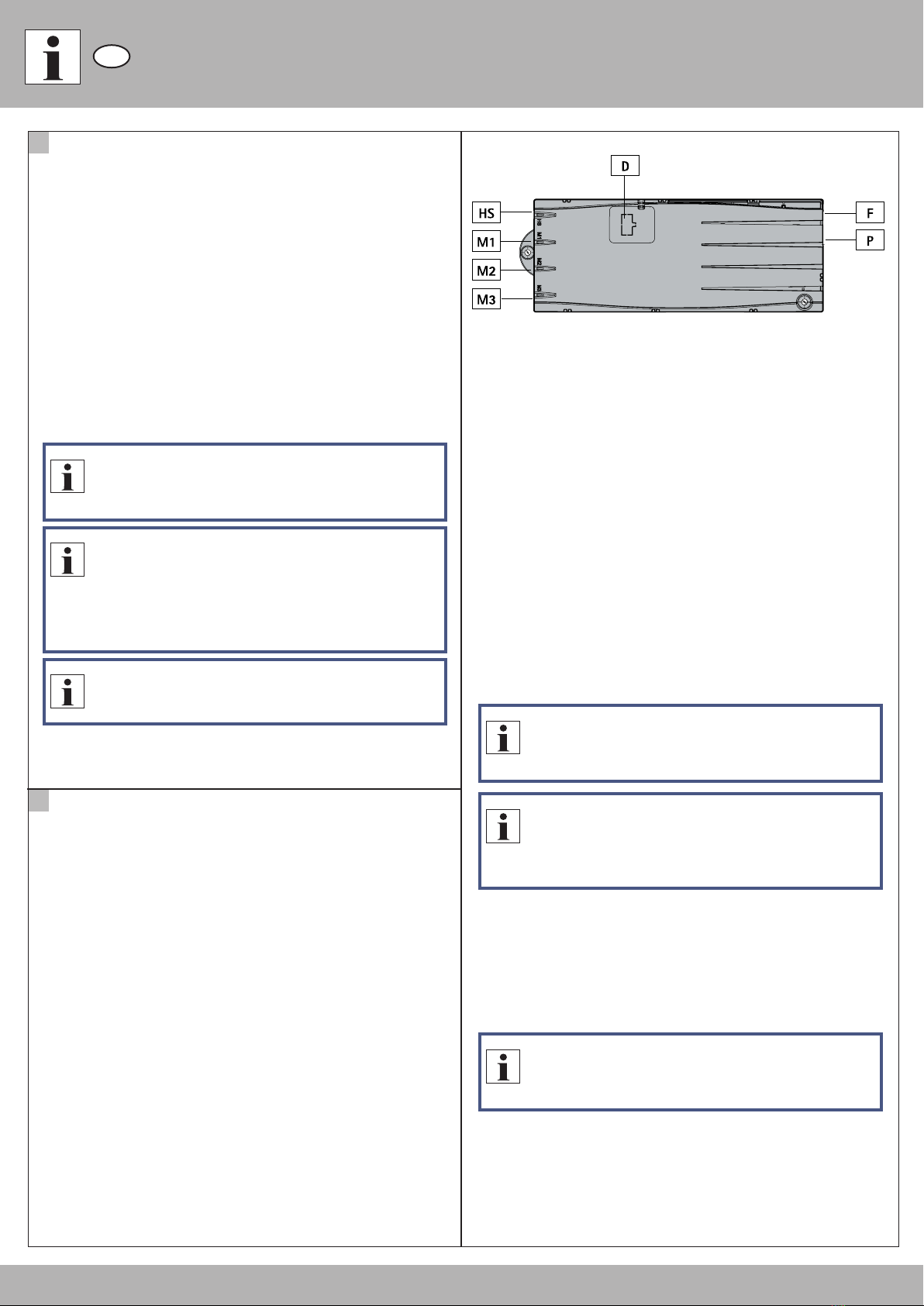
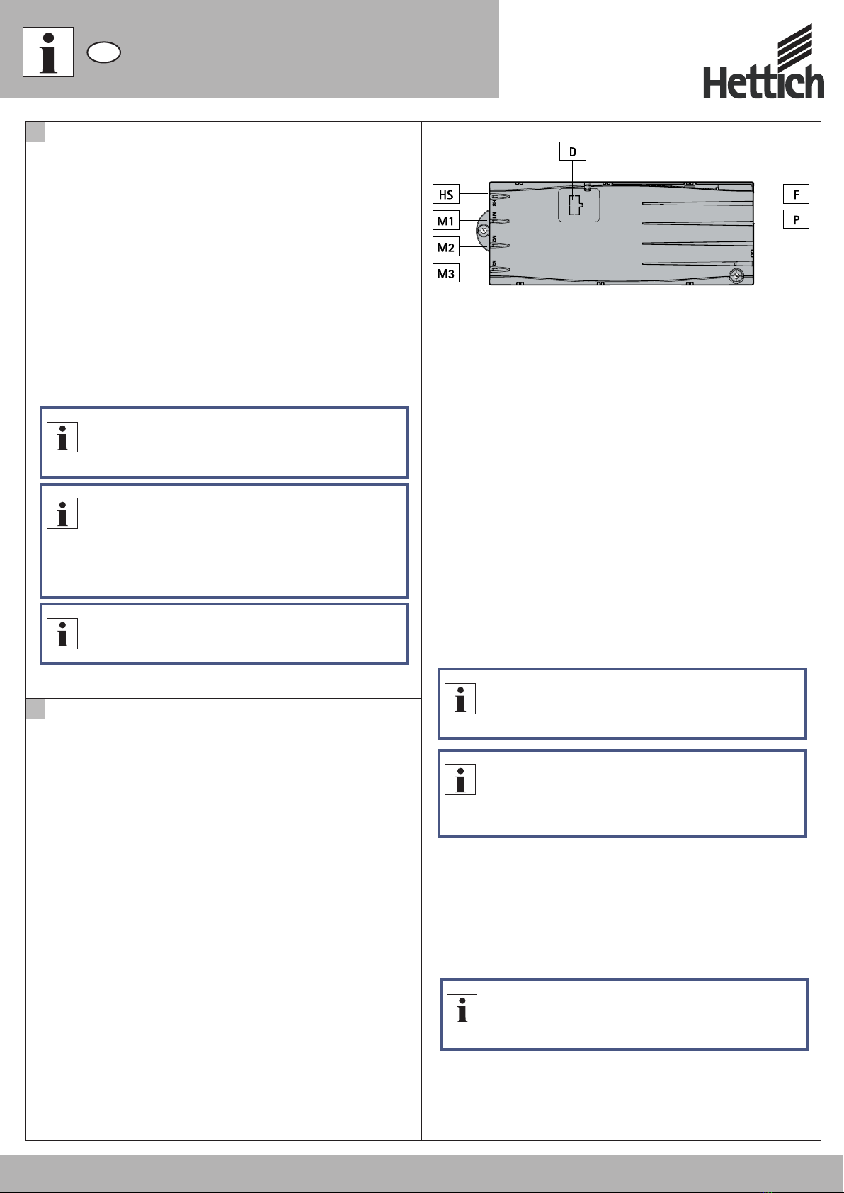
D
Betrieb des kaskadierten Verbundes
3
3.1 Änderung des Kaskadierverbundes
Sollte es nötig sein, innerhalb eines Kaskadierverbundes eine oder mehrere
Steuerungen zu tauschen, so ist folgende Vorgehensweise zu beachten:
1. Bevor Sie die betroffenen Steuerungen durch neue austauschen, setzen
Sie alle Steuerungen des geplanten Verbundes auf Werkszustand zurück
(siehe Kapitel 3.2).
2. Trennen Sie den gesamten Kaskadierverbund von der Stromversorgung.
3. Stellen sie den Kaskadierverbund her ( ).siehe Kapitel 2
3.2 Steuerung auf Werkseinstellung zurücksetzen (S0-Menü)
Mit dieser Funktion kann die Steuerung auf Werkseinstellungen
zurückgesetzt werden.
Hinweis
Vermeiden Sie unbedingt das Anschließen einer Steuerung, die
sich nicht im Werkszustand befindet.
Hinweis
Durch den Aufruf des S0-Menüs werden alle Steuerungen im
Verbund auf die Werkeinstellungen zurückgesetzt.
Hinweis
Der Verbund muss grundsätzlich vor jeder Veränderung
(Parameter, Konfiguration) in den Werkszustand gebracht
werden.
1. Drücken Sie gleichzeitig die Memoryposititonstasten 1,
2 und die Taste Tischplatte nach oben. Halten Sie diese
Tastenkombination ca. 3 Sekunden gedrückt. Lassen Sie
dann die Tasten los.
Am Display wird S und eine Nummer, z.B. S 1 angezeigt.
2. Drücken Sie so oft die Taste Tischplatte nach oben bis
am Display S 0 angezeigt wird.
Am Display wird S 0 angezeigt.
3. Drücken Sie die Memorytaste.
Am Display wird E70 angezeigt.
4. Ziehen Sie das Netzanschlusskabel heraus und stecken
es nach ca. 5 Sekunden wieder ein.
Die Steuerung wird auf Werkseinstellungen zurück
gesetzt.
Die Steuerung befindet sich nun im selben Zustand wie
vor der Erstinbetriebnahme.
21
SAVESAVE
2.6 Erster Reset der Hubsäulen
Nachdem die Steuerungen ein erstes Mal mit der Spannungsversorgung
verbunden wurden, ist es nötig einmalig den Reset der Hubsäulen zu
durchlaufen, da hierbei auch die Adressierung des Kaskadierverbundes
durchgeführt wird.
Hinweis
Es dauert ca. 5 Sekunden bis die Hubsäulen mit der Resetfahrt
beginnen.
Hinweis
Tritt während des Reset ein Fehler auf (Fehlermeldung am
Display, fehlerhaftes Verhalten der Hubsäulen) muss der
Kaskadierverbund in den Werkszustand gebracht werden (S0-
Menü).
Warnung
Achtung: Unbedingt entweder direkt beim oder unmittelbar
nach dem Reset überprüfen, ob sich die jeweiligen Hubsäulen
auch bewegen
System kann ansonsten durch schiefes Anfahren
zerstört werden.
1. Am Display muss 000 blinken. Dies signalisiert, dass das
System auf einen Reset wartet.
2. Drücken Sie die Taste Tischposition nach unten.
Nun sollten die Hubsäulen mit verminderter Geschwindigkeit
in die Resetposition gefahren werden. Die Taste darf erst
nach Erreichen der Endposition, welches durch ein Klicksignal
signalisiert wird, losgelassen werden!
3. Warten Sie mindestens 3 Sekunden nach dem Reset. In
diesem Zeitfenster wird die Hubsäulenerkennung
abgeschlossen und gespeichert.
4. Am Display wird nun die aktuelle Tischplattenposition
angezeigt.
2.5 Stromversorgungskabel anschließen
Bevor Sie alle Steuerungen mit Strom versorgen, vergewissern Sie sich, dass
die vorhergehenden Schritte korrekt durchgeführt wurden und der Verbund
prinzipiell einem in Kapitel 4.1 dargestelltem Verbund entspricht.
Warnung
Bevor Sie die Stromversorgungskabel anschließen, überprüfen
Sie nochmals
ob die Netzspannung dem Typenschild Ihrer Steuerung
entspricht,
ob alle Komponenten an den richtigen Buchsen
angeschlossen sind.