Hewland TMT-200 User manual

Hewland Engineering Ltd
Waltham Road, White Waltham
Maidenhead, Berkshire, SL6 3LR, UK
+44 (0) 1628 827600
info@hewland.com
www.hewland.com
GEARBOX MANUAL
Issue: 20
Date: 16/10/2020
TMT-200

©Hewland Engineering Limited 2017 1
LIMITATION OF LIABILITY AND WARNING
The Hewland products and transmissions which are detailed herein are intended to be used in motorsport activities and are therefore subject to the following warning:
A) Hewland products are intended for use in or as high speed and high performance racing vehicles. The racing of high speed and high performance vehicles can be a very hazardous
activity and therefore involves a high risk of personal injury or even death. Hewland products will not withstand all foreseeable impacts during their normal intended use in or as a racing vehicle
without the likelihood of serious personal injury or death to the driver and/or passenger(s) or of damage to the Hewland products themselves which may impact the products performance and safe
use.
B) Hewland products should only be driven or used:
1. By a driver with the requisite training, skill and experience necessary both for the conditions under which the products are to be used and for the racing of high speed and high
performance vehicles
2. On specially designed racing tracks and under the supervision of official and approved racing organisations or otherwise under proper and reasonable operating conditions supported
by appropriate safety, medical and rescue services
3. With proper maintenance and repairs effected to parts and gearboxes as all parts and gearboxes, being mechanical devices, are inherently subject to wear and tear, fatigue or
disintegration and/or damage due to collision or improper use.
WARNING
The information and/or graphics presented in this Hewland Gearbox Service Manual may include inaccuracies or typographical errors. Changes and/or improvements may also be made to the
information presented herein without notice at any time. Hewland Engineering Limited makes no representations about the suitability, reliability, availability, timeliness or accuracy of the information
and/or graphics presented herein. All such information and/or graphics are provided on an “AS IS” basis without warranty, representation or guarantee of any kind, express or implied. Hewland
Engineering Limited hereby disclaims, to the fullest extent permitted under law, all warranties and conditions with regard to this information and/or graphics, including all implied warranties and
conditions of merchantability, fitness for a particular purpose, and workmanlike effort.
The user of the information and/or graphics contained in thisHewland Gearbox Service Manual is solely responsible for its use. If the user is dissatisfied with any such information and or graphics,
or with the terms of use, the user’s sole and exclusive remedy is to discontinue using the information and/or graphics. In no event shall Hewland Engineering Limited be liable for any direct,
indirect, incidental, special or consequential damages whatsoever, including without limitation, damages for accident, injury, property damage, loss of use, loss of data or loss of profits (whether
such damages are based on contract, tort, negligence, strict liability or otherwise, even if Hewland Engineering Limited has been advised of the possibility of damages arising), arising out of or in
any way connected with:
1. The use or performance of the information and/or graphics presented in this Hewland Gearbox Manual
2. Any inability to use such information and/or graphics,
3. any other use of such information and/or graphics.

©Hewland Engineering Limited 2017 2
CONTENTS
Limitation Of Liability And Warning.............................................................................................................................................................................................................................................. 1
Figures............................................................................................................................................................................................................................................................................................. 4
Technical Specification.................................................................................................................................................................................................................................................................. 5
Recommended Tightening Torques............................................................................................................................................................................................................................................ 6
Recommended Loctite Use .......................................................................................................................................................................................................................................................... 7
General Notes................................................................................................................................................................................................................................................................................. 8
Differential Bearing Preload.......................................................................................................................................................................................................................................................... 9
Pinion Height Settings................................................................................................................................................................................................................................................................. 10
Pinion Bearing Preload................................................................................................................................................................................................................................................................ 11
Crownwheel & Pinion Backlash Setting.................................................................................................................................................................................................................................... 12
Sequential Barrel Setting ............................................................................................................................................................................................................................................................ 13
DIFFERENTIALS............................................................................................................................................................................................................................................................................... 14
Powerflow Differential................................................................................................................................................................................................................................... 15
Differential Settings....................................................................................................................................................................................................................................... 16
TPT Differential Assembly ........................................................................................................................................................................................................................... 17
Gearbox Assembly –(Manual Gear Shift)................................................................................................................................................................................................................................ 18
Gearbox Assembly –(Pneumatic Gear Shift).......................................................................................................................................................................................................................... 20
Changing Gear Ratios................................................................................................................................................................................................................................................................. 21
ILLUSTRATED PARTS LIST .............................................................................................................................................................................................................................................................. 22
Output Assembly.......................................................................................................................................................................................................................................................................... 23
Casing Parts (Without Integral Gear Shift Compressor) ........................................................................................................................................................................................................ 24
Casing Parts (With Integral Gear Shift Compressor).............................................................................................................................................................................................................. 25
Layshaft Assembly....................................................................................................................................................................................................................................................................... 26
Pinion Shaft Assembly................................................................................................................................................................................................................................................................. 27
Gear Shift Assembly (Manual Gear Shift Only)....................................................................................................................................................................................................................... 28
Gear Shift Assembly (Pneumatic Gear Shift Only) ................................................................................................................................................................................................................. 29

©Hewland Engineering Limited 2017 3
Input Assembly............................................................................................................................................................................................................................................................................. 30
Barrel/Potentiometer Interfaces ................................................................................................................................................................................................................................................. 31
Temperature & Pressure Sensor Positions.............................................................................................................................................................................................................................. 32
Part Numbering ............................................................................................................................................................................................................................................................................ 33
Output Flange Options ................................................................................................................................................................................................................................................................ 41
TMT Typical Oil System Layout................................................................................................................................................................................................................................................. 43
Running Without An Oil Cooler.................................................................................................................................................................................................................................................. 44
Revision History............................................................................................................................................................................................................................................................................ 45
`

©Hewland Engineering Limited 2017 4
FIGURES
Figure 1-This table is taken from Hewland Standard: DOS-006-V4 ...................................................................................................................................................................................................... 6
Figure 2-This table is taken from Standard: DOS-006-V4 ..................................................................................................................................................................................................................... 7
Figure 3- Dierenal Bearing Preload................................................................................................................................................................................................................................................... 9
Figure 4-Pinion Height Seng ............................................................................................................................................................................................................................................................ 10
Figure 5- Pinion Bearing Preload......................................................................................................................................................................................................................................................... 11
Figure 6- Crownwheel & Pinion Backlash Seng ............................................................................................................................................................................................................................... 12
Figure 7- Sequenal Barrel Seng ..................................................................................................................................................................................................................................................... 13
Figure 8- Powerow Dierenal......................................................................................................................................................................................................................................................... 15
Figure 9- Dierenal Sengs ............................................................................................................................................................................................................................................................. 16
Figure 10- TPT Dierenal Assembly .................................................................................................................................................................................................................................................. 17
Figure 11- Output Assembly ............................................................................................................................................................................................................................................................... 23
Figure 12- Casing Parts Without Integral Gear Shi Compressor ....................................................................................................................................................................................................... 24
Figure 13- Casing Parts With Integral Gear Shi Compressor ............................................................................................................................................................................................................ 25
Figure 14- Laysha Assembly.............................................................................................................................................................................................................................................................. 26
Figure 15- Pinion Sha Assembly........................................................................................................................................................................................................................................................ 27
Figure 16- Gear Shi Assembly (Manual Gear Shi)........................................................................................................................................................................................................................... 28
Figure 17- Gear Shi Assembly (Pneumac Gear Shi)...................................................................................................................................................................................................................... 29
Figure 18- Input Assembly .................................................................................................................................................................................................................................................................. 30
Figure 19- Barrel / Potenometer Interfaces ..................................................................................................................................................................................................................................... 31
Figure 20- Temperature & Pressure Sensor Posions ........................................................................................................................................................................................................................ 32
Figure 21- Output Flange Opons....................................................................................................................................................................................................................................................... 41
Figure 22- Transmission Tooling ......................................................................................................................................................................................................................................................... 42
Figure 23- TMT Typical Oil System Layout .......................................................................................................................................................................................................................................... 43
Figure 24- Running Without An Oil Cooler.......................................................................................................................................................................................................................................... 44

©Hewland Engineering Limited 2017 5
TECHNICAL SPECIFICATION
The TMT gearbox is a transaxle unit, designed for mid-engined, rear wheel drive cars. The unit is produced with six forward gears, reverse, and a powerflow
differential.
The gear selection mechanism is sequential, and is available as either a pneumatically actuated semi-automatic or a mechanically operated direct link, both
have reverse engagement locked out.
The gear selection order is Rev - Neutral - 1st 2nd 3rd 4th 5th & 6th
The drive is taken from the engine via the clutch shaft, to the layshaft, through gears to the pinion shaft, and then onto the crownwheel and differential assembly.
Gear changing is effected through non-synchronising face dogs. An extensive range of gear ratios provides a wide range of gearing requirements. The gear
ratios and differential assembly can easily be changed without removing the gearbox from the vehicle.
Heat treated nickel chrome steel is used to manufacture all gears and shafts. The selector forks are also steel. Lubrication is by internal pump with distribution
circuit, and the oil is retained by lipped oil seals.
In general configuration, the TMT-200 is a high tech racing transaxle unit which achieves the maximum effective use of power, in conjunction with extremely
stiff integral rear suspension mountings.
1st to 6th gear ratios from 3.083:1 to 0.9230:1
Note: Overdrive ratios need proof maching found in TMT-202 version 12 and above.
Final drive ratios 8/35, 9/35, 10:31 & 11/31
Clutchshafts made to customer's requirements
WEIGHT
Aluminium 49.5kg / Magnesium 44.5kg
OIL GRADE
SAE 80 or SAE 90
OIL QUANTITY
1.75ltr (not including oil cooler circuit)
MAXIMUM TORQUE
320lbs.ft (430Nm) –reduced to 275lbs.ft (373Nm) for 8:35 final drive

©Hewland Engineering Limited 2017 6
RECOMMENDED TIGHTENING TORQUES
Final Drive Bolts
100
Nm
Pinion Shaft Nut
163
Nm
Differential Centre Bolt
80
Nm
Selector Barrel Bolt
48
Nm
All Studs
12
Nm
Nm lb/ft Nm lb/ft Nm lb/ft Nm lb/ft Nm lb/ft Nm lb/ft
Fine M3x0.35 1.4 1.1 0.8 0.6 0.5 0.4 1.7 1.2 1.2 0.9 0.7 0.6
Course M3x0.5 1.4 1.0 0.8 0.6 0.5 0.4 1.6 1.2 1.3 0.9 0.8 0.6
Fine M4x0.5 3.5 2.5 2.0 1.4 1.2 0.9 4 3 3 2 1.8 1.3
Course M4x0.7 3.0 2.5 1.8 1.4 1.2 0.9 4 3 3 2.5 2 1.4
Fine M5x0.5 7 5 4 3 2.5 2 8 6 5 4 3.5 2.5
Course M5x0.8 6 5 4 3 2.5 2 7 5 6 4 3.5 3.0
Fine M6.0.75 11 8 7 5 4 3 13 10 10 7.0 6 4.5
Course M6x1.0 11 8 6 5 4 3 13 910 8 7 5
Fine M8x1.0 27 20 16 12 10 732 23 23 17 14 11
Course M8x1.25 26 19 15 11 10 731 23 24 18 15 11
Fine M10x1.25 53 39 31 22 19 14 62 46 44 33 28 21
Course M10x1.5 51 38 30 22 19 14 60 44 46 34 29 22
Fine M12.x1.5 91 67 53 39 34 25 107 79 76 56 48 36
Course M12x1.75 89 66 52 38 33 24 104 77 79 58 50 37
UNF 1/4x28 14 10 8.0 6.0 5.0 4.0 16 12 12 9 8 6
UNC 1/4x20 13 10 8.0 6.0 5.0 3.5 16 12 14 10 9 6
UNF 5/16x24 27 20 16 12 10 732 24 23 17 15 11
UNC 5/16x18 26 19 15 11 10 731 23 25 19 16 12
UNF 3/8x24 48 35 28 20 18 13 56 41 38 28 24 18
UNC 3/8x16 46 34 27 20 17 12 54 40 43 32 27 20
UNF 7/16x20 76 56 44 32 28 21 89 66 61 45 39 29
UNC 7/16x14 73 54 42 31 27 20 86 63 68 50 43 32
Metric
Imperial
Direct in material
Steel Insert (Helicoil, Timesert, Keensert)
Nut Torque
Nut on EN16 Stud
Torque in Magnesium
Torque in Steel
Torque in Aluminium
Torque in Magnesium
Torque in Aluminium
Unless otherwise specied within this manual.
Figure 1-This table is taken from Hewland Standard: DOS-006-V4

©Hewland Engineering Limited 2017 7
RECOMMENDED LOCTITE USE
Loctite
222
Loctite
243
Loctite
270
Loctite
542
Loctite
648
Permanent
fixings
Studs being fitted to holes tapped directly into base material
✔
Fixing timesert or keensert into tapped hole in base material
✔
General fixings
Screws / bolts being fitted to holes tapped directly into base material
✔
Screw / bolt into timesert
✔
Screws / bolts fitted to heli-coil fixings
(LAST RESORT IF LOCKWIRE CANNOT BE USED)
✔
Specific
fixings
Oil line blanking plugs
✔
Differential cap bolts / studs
✔
Pinion / Mainshaft / Layshaft nut
(ONLY IF LOCKING DEVICE IS NOT INCORPORATED INTO DESIGN)
✔
Crownwheel bolts / studs
✔
Selector barrel Nut
✔
Pinion bearing retaining bolts
✔
Figure 2-This table is taken from Standard: DOS-006-V4
Unless otherwise specied within this manual.

©Hewland Engineering Limited 2017 8
GENERAL NOTES
Read these instructions carefully and with reference to the illustrations.
Before dismantling the gearbox, see that a clean tray is available, in which to place the parts.
Thoroughly clean and inspect all parts before reassembly. Discard any worn or damaged components and replace with new ones.
Use only genuine Hewland parts as replacements. These are manufactured in our workshops to the fine tolerances necessary and are rigorously
inspected.
Always ensure that locknuts, and oil seals are in good condition when reassembling.
All studs and screws must be Loctited or wirelocked in position, unless stated otherwise.
Bearing Replacement :-
oBearings can only be removed or renewed if the casings have been warmed in an oven, or with a blowlamp. In the latter case, keep the blowlamp
moving while heating the casing.
oNB. Do not overheat. Test with a spot of water which will bounce off at the correct temperature. Once a casing is heated, all bearings
should be pressed into their respective seating’s without delay, thus eliminating the needto reheat. At the correct temperature, fitting the bearings
should present no difficulty.
oDuring cooling, or when the casings have cooled, it is advisable to once more lightly press the bearings to ensure that they are correctly seated.
Oil:-
oFill the gearbox through the oil filler hole on top of the maincase. The oil will find its own level within the gearbox.
oNB. Too much oil will not directly cause any harm, but is undesirable as it will induce power loss and overheating of the internals.

©Hewland Engineering Limited 2017 9
DIFFERENTIAL BEARING PRELOAD
Using the original shims (40) as a guide, fit the outer races of bearings (37) to
the maincase and side cover. Fit the inner races of the bearings to the differential
case. Offer up the differential assembly to the maincase and fit the sideplate.
Adjust shims (40) as necessary to achieve 0.012”/0.015” of preload, giving 4/6 lb
ft (5.4/8.1 Nm) torque to turn.
(With bearings oiled.)
Refer to page 19 for part references.
The table below is to inform you of which sideplate spacers should be used with
which crownwheel when mounted on a TPT differential. The reason that there
are two sets of spacers, is that the crownwheels have different mounting
distances. The table also shows which crownwheel Bolts should be used with
each crownwheel, as shorter bolts are required for the 11/31 CW.
PART NUMBER
RATIO
MOUNTING
DISTANCE
ITEM (41)
ITEM (68)
CW BOLTS
ITEM (126)
TMT-221-EW
8/35
2.100”
FGC-206-2D
NLT-206-2
VG-221-1
TMT-221-CW
9/35
2.200”
FGC-205-2A
NMT-205-2A
VG-221-1
NMT-221-BW
10/31
2.316”
FGC-206-2A
NMT-205-2
VG-221-1
NMT-221-AW
11/31
2.316”
FGC-206-2A
NMT-205-2
VG-221-1C
Refer to page 19 for part references.
Figure 3- Dierenal Bearing Preload

©Hewland Engineering Limited 2017 10
PINION HEIGHT SETTINGS
Special tools required: SK-1470-A
Press the inner race of the pinion head bearing
(67) Onto the pinion shaft (69). Fit the bearing outer race
and nominal shim pack (66) into the maincase (102).
Assemble the pinion shaft into the maincase, then fit the tail
bearing outer race (14) to the bearing carrier (105), and
secure it to the maincase. Tighten the pinion shaft nut (110)
onto the pinion shaft until the shaft requires 20-25 lbs.in
(2.2-2.8Nm) to turn it in its bearings.
Fit tool SK-1470-A into the maincase diff bearing bore, and
use feeler gauges to measure the gap between the tool and
the pinion shaft front face. This clearance should comply
with the dimension indicated on the
crownwheel & pinion label (also etched on the head of the
pinion shaft), and can be adjusted by reducing the peelable
shimpack (66) behind the pinion head bearing outer race.
Refer to page 19 for part references.
Alternatively, the pinion mounting distance can be measured with a height
gauge, and set to the dimension indicated on the pinion shaft label.
(Also etched on the head of the pinion shaft).
NB. It is not correct practice to replace a pinion shaft without checking the setting
distance, even if the old and newshafts have the same recorded setting distance.
It is also good practice to renew the pinion head bearing if the pinion shaft is being
replaced.
Figure 4-Pinion Height Seng

©Hewland Engineering Limited 2017 11
PINION BEARING PRELOAD
Having obtained the correct pinion setting, remove
The bearing carrier (105). Add the reverse gear spacer (71), reverse
gear inner track (109), reverse clutch ring (31), 3 off hubs (2) and
spacer (108) to the pinion shaft. Replace the bearing carrier (105),
bearing inner race (24) and pinion nut (110). Tighten the pinion shaft
nut until the shaft requires 20-25 lbs.in (2.2-2.8Nm) to turn it in its
bearings.
If necessary adjust the preload across the bearings by grinding the
pinion shaft spacer (71) on its pinion bearing face to reproduce the
pinion shaft setting figure (see previous page) It is essential that if
any component on the mainshaft is renewed, then the bearing preload
must be checked and adjusted as required.
Refer to page 19 for part references.
NB. It is essential that the pinion bearing
preload is checked and adjusted if any of the pinion shaft
components are replaced, with
the exception of the locknut and locking ring. Fitting a longer
reverse gear spacer (71) will
decrease the pinion bearing preload, whereas shortening the
reverse gear spacer (71) will
increase the pinion bearing preload.
Figure 5- Pinion Bearing Preload
©Hewland Engineering Limited 2017 12
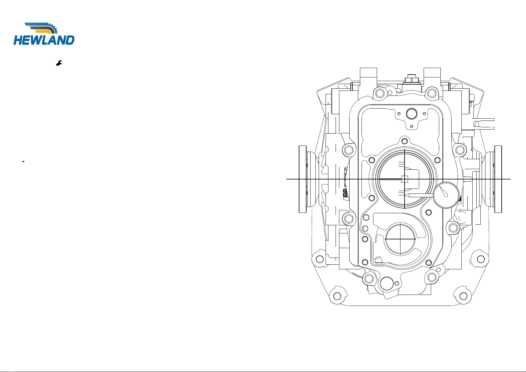
CROWNWHEEL & PINION BACKLASH SETTING
Special tools required: SK-1913
With the pinion shaft, differential assembly, and sideplate fitted, and the correct diff
bearing shims ascertained, the actual backlash can be measured by means of a dial
test indicator against the relevant crownwheel & pinion ratio mark etched in the face of
tool SK-1913. Be sure to take at least 6 backlash readings, turning the crownwheel 30-
45 degrees between each reading (this is to ensure that any variation due to
manufacturing tolerances are taken into account). The backlash variation from
manufacture will be logged on the gear data card supplied with each crownwheel &
pinion set.
The correct minimum backlash figure should be 0.005” (0.13mm) taken at the tightest
point of gear mesh. If the measured backlash is incorrect, rectify it by removing some
shims (40) from behind one diff bearing, and inserting the equivalent amount of shim
behind the other, thus moving the diff across in the maincase.
NB. Generally 0.001” of crownwheel axial adjustment equates to 0.0008” modification
in gear set backlash.
Do not add or discard any shims, as to do so will affect the differential bearing preload.
NB. Dummy bearings can be used to ease the shim change during the setting
procedures. However, before fitting the actual differential bearings, it is important to
compare their width with that of the dummy bearings and compensate the shim
thicknesses for any difference.
Figure 6- Crownwheel & Pinion Backlash Seng

©Hewland Engineering Limited 2017 13
SEQUENTIAL BARREL SETTING
Special tools required: SK-2311
Build up the assembly into the maincase, and fit the fork setting fixture as shown, making
sure that the barrel is in the neutral position before securing the face plate of the fixture.
Measure and record the dog face clearance for 5th and 6th gears. Their position in the
maincase, (furthest away from the datum face), means any dog clearance errors due to
tolerance build up, will be at their worst. Therefore it is acceptable to adjust the barrel
position according to these readings. Any difference in the dog face clearance between
these gears must be averaged out by changing the barrel setting spacer (32). Spacers of
various thicknesses are available, as shown in Fig.6.
In order to change this spacer, the face plate of the fixture, the mainshaft locknut (110),
selector rail (114), selector forks (22) and the barrel bolt (118) must be removed. (Please
note for clarity the selector rail (114) and selector forks (22) have not been shown in Fig.6).
Removal and replacement of the barrel bolt (118) is madeeasier if a suitable tool is located
into the radial hole in the barrel (117) and the reverse blocker hole in the maincase above
it.
NB. It is not possible (or necessary) to individually adjust each fork.
Figure 7- Sequenal Barrel Seng

©Hewland Engineering Limited 2017 14
DIFFERENTIALS

©Hewland Engineering Limited 2017 15
Powerflow Differential
This powerflow differential unit is designed with versatility as its major asset. Many factors will contribute to the settings required. A car with good traction and
low power, may require a completely different arrangement to that of a car with poor traction and high power. There are 10 friction plates within the unit (4
splined to the diff casing, and 6 splined to the side bevel gears). Slip limiting is dependent on the friction resistance between these plates, and is affected by
clamping the plates together. Four factors contribute to the total friction torque between the plates:-
1)The side bevel gears thrust apart to clamp the plates as they transmit the driving
power. This is a feature of the gear geometry, and is not adjustable.
2) The side ring gear ramp angles have an effect on how much of the transmitted
torque is converted into sideways (clamping) force onto the plates. For example,
on the drive side of the ring gear, 45 degrees transmits less sideways force than
30 degrees. Likewise on the coast side of the ring gear, an 80 degree angle will
transmit little or no clamping force onto the plates, whereas a 45 degree angle will
transmit a much greaterforce. The side rings gearare available with many different
drive/coast ramp angle combinations.
3) The second adjustable factor is how tightly the plate stack is compressed on
assembly (known as static preload). The preload torque is measured between the
side bevel gears, by holding one side bevel gear stationary, and measuring the
torque required to turn the other.
NB. Figure 8 shows a belleville spring fitted to the plate stack, that can be
used to maintain static preload during the “running in” period.
4) The final adjustment is simply to re-order the plate stack so as to change the
number of relatively rotating faces. The diagram shows the stack setup with the
maximum 12 working faces. Standard stack may be shuffled to give as few as 2
working faces.
Figure 8- Powerow Dierenal

©Hewland Engineering Limited 2017 16
Differential Settings
This table is intended as a quick reference guide to percentage lock various setting permutations.
30 degree ramps with 12 working plate surfaces has been set as the 100% benchmark.
Percentage Rating
Ramp Angle
No. of Friction Surfaces
4
85
2
4
80
2
7
85
4
7
60
2
8
80
4
11
85
6
11
45
2
13
80
6
14
85
8
15
60
4
17
80
8
17
30
2
18
85
10
21
85
12
21
80
10
22
60
6
22
45
4
25
80
12
30
60
8
33
45
6
33
30
4
37
60
10
43
45
8
45
60
12
50
30
6
54
45
10
65
45
12
67
30
8
83
30
10
100
30
12
Figure 9- Dierenal Sengs
©Hewland Engineering Limited 2017 17
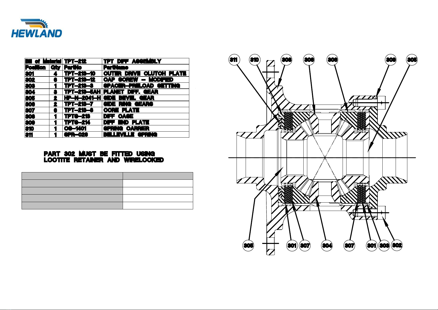
TPT Differential Assembly
Various Bellville springs (311) and Carriers (310) are available.
The first preload value given is the initial value that will be given without any additional shims.
Shims can be added to the carrier to give higher preloads if required.
SPRING AND CARRIER
PRELOAD RANGE
SPR-026 WITH CS-1401
85-145 Lbs.Ft
SPR-032 WITH CS-1401
0-140 Lbs.Ft
SPR-065 WITH CS-1401
0-110 Lbs.Ft
SPR-150 WITH TPT-213-3SP
40-80 Lbs.Ft
Figure 10- TPT Dierenal Assembly

©Hewland Engineering Limited 2017 18
GEARBOX ASSEMBLY – (MANUAL GEAR SHIFT)
It is assumed that all bearings, oil seals, studs, oil jets, and dowels are already fitted into their casings.
Slide the reverse idler top hat bush (48) into place in the maincase (102), then push it in as far as it will go. Slide the second reverse idler top hat bush
(34) into place, then pull it towards the rear of the maincase. Press the bearing (52) into the reverse idler gear (33), slide the sleeve (49) into the bearing,
and position the gear between the bushes. Push the reverse idler top hat bush (34) towards the front of the maincase, fit the screw (87), and lockwire.
Press the dowel (35) into the maincase, and secure the detent arm (82), trunion (51), and spring (83) into the maincase using screw (59) and washer
(53).
Position the pawl (91) in the slot in the selector rack (153), and press pin (30) into place ensuring that it does not protrude outside the rack outer diameter,
and movesfreely. Slidethe washers (50), spring (155), and sleeve (156) onto the rack and securethem with circlip (16).This spring has a limited effective
life, therefore periodic replacement is recommended. It is also advisable never to re-use the circlip (16).
Fit the quad ring seal (154) carefully into the seal carrier (152), then assemble it onto the maincase using screws (90) ensuring o-ring (78) is fitted. Fit
the spring carrier (151), into the maincase, oil the rack liberally and slide it in, ensure that it travels back and forth without any stiction. Fit the anti-rotation
pin (93) and washer (128) into the maincase.
Put the fork setting spacer (32) onto the barrel (117) and whilst holding the detent arm against its spring using a pair pliers feed the barrel into the
maincase and secure with the barrel bolt (118). It may be necessary to lift the pawl up so as to let the barrel pass underneath it.
Slide the plunger (92), spring (1) and washer (36) into the rack and secure with circlip (15), then fit rack cover (150) and o-ring (78), using screws (90).
NB. If the gearbox has not yet been fork set, then delay this step, as it easier to push the pawl up if it has not yet been fitted with its return spring.
Assemble the bell crank (162), bearings (160), spacer (161), washers (158) and shim washer (159) to the maincase and secure with screw (157) and
nut (163). Ensure by adjusting the shim washer thickness that the selector operates smoothly in both directions, and self-returns to its normal position.
Fit the bearing (28) onto the clutchshaft (18) and secure using circlip (26). Fit oilseal (44) into slave adaptor (116), and slide the slave adaptor over the
clutchshaft to enable fitting of bearing circlip (27). Offer up clutchshaft assembly to the maincase with o-ring (29) in place and secure with screws (90).

©Hewland Engineering Limited 2017 19
The gear cluster can now be loaded into the maincase, (this is assuming that the pinion, and pinion bearing preload have been set as previously
described). With the pinion shaft (69) complete with the pinion head bearing (67) inner race held in position in the maincase the pinion gears, spacers,
hubs, bearings and clutchrings can be slide onto it. It is necessary tofit the relevant selector forks in conjunction with their clutchring, locating the selector
fork pin into the barrel track, once all four forks are correctly located with their clutchring, and the barrel, then the selector rail (114) can be slid through
all of the forks and into the maincase. The layshaft, input gears, and spacers can now also be assembled into the maincase. (See figure 14 for details of
both layshaft designs). NB The pinion gears may need rotating in order to allow the input gears to pass and mesh properly.
The bearing carrier (105) can now be fitted with the barrel oil seal (64), barrel bearing (8), pinion shaft bearing outer (14), layshaft bearing outer race
(11), and secured onto the maincase, ensuring that the o-ring cord (125) has been correctly fitted into its groove.
The pinion shaft bearing inner race (24), and locknut (110) can now be fitted and tightened to the recommended torque, the locknut locking ring (72) and
retaining circlip (43) can now be applied.
The oil pump gears (112), (120), and rear cover (123) can now be fitted ensuring that the o-ring (76) has been correctly located in its groove.
Fit the output shaft oilseal (39), bearing (38), and output flange (107) in the maincase, securing it with circlip (23). Fit similar parts intothe sideplate (106).
Assuming that the differential bearing preload and the crownwheel and pinion backlash have been set as previously described, then the differential can
be fitted into the maincase, and the sideplate (106) secured into position ensuring that the o-ring (81) is fitted.
Fit all ancillary parts, oil filters, pinion oil spray, breather and oil fittings.
s) Assemble the neutral/reverse blocker and fit it into the maincase above the barrel. NB When installing the gearbox into the car, the blocker release
cable length should be adjusted so that the blocker plunger is held just clear of the barrel when a forward gear is selected.
Refer to page 19 for part references.
Table of contents
Other Hewland Microphone System manuals


