Hewlett Packard Enterprise Aruba User Experience Insight User manual

ARUBA USER EXPERIENCE INSIGHT
QUICK START GUIDE
MAY 15TH 2018

UXI Quick Start Guide
May 2019
Page 2
Revision
Date
Author
Notes
15.05.19
Johnny Vo
Initial – created for “May 2, Dashboard Upgrade”
29.05.19
Johnny Vo
v2 – updated for wired testing enhancements
Scope
Aruba’s User Experience Insight Sensor provides alerts and reporting on the network’s
performance completed by sequential testing. This guide was created to help users set
up their sensors, from activating their subscription to configuring tests. This guide will
not cover the sales administration and the ordering process. External guides will be
linked if further explanation is required. Infrastructures will vary, this guide will attempt
to cover all use cases for provisioning the sensor. The dashboard GUI may change and
functionality may be added over time, this guide will be updated for major updates.
Support is always available to assist and answer any questions you may have on the
sensor. The team is not limited to troubleshooting but can assist with provisioning,
configuration and management of the sensor. You can find a chat bubble on the
dashboard or email support@capenetworks.com. There are also more guides available
here https://help.capenetworks.com which I have referenced in many sections.

UXI Quick Start Guide
May 2019
Page 3
Table of Contents
Provisioning 4
Demo 4
Subscription 5
Initial Configuration 6
Wizard 6
Settings 7
Group Management 8
Adding an SSID 9
Associating to an SSID 10
SSL Certificate Installation 11
Creating Tests 12
Advanced Testing 13
Multiple SSIDs 13
Setting up Ethernet testing 14
BSSID Locking 15
Threshold Adjustments 16
NAPLAN Testing (AU) 17
UXI Quick Start Guide
May 2019
Page 4
PROVISIONING
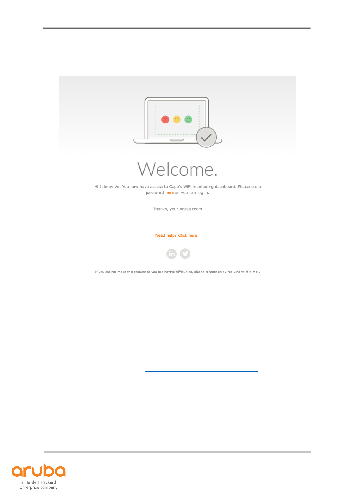
Figure 1.1 Welcome Email
Demo
Prior to receiving your sensor, you should have received an email to create a password
for your new login for the dashboard as show in Figure 1.1. Please follow the prompts
and create an account to have access to the Aruba UXI Dashboard.
If you have not received this email, please advise your sales rep or contact support at
support@capenetworks.com with your sensor serial to check the status.
The dashboard is available here: https://dashboard.capenetworks.com
UXI Quick Start Guide
May 2019
Page 5
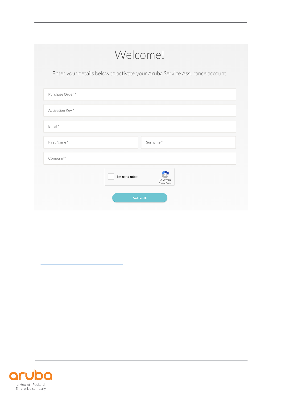
Figure 1.2 Activate License Key Form
Subscription
For paying customers, once you receive your PO and license key, please head on over
to https://capenetworks.com/activate to request provisioning for your sensor as shown
in Figure 1.2. If you do not have a license key, put “NO” in the field. Once provisioned,
you will also receive an account creation email as shown in Figure 1.1.
The dashboard is available here after activation: https://dashboard.capenetworks.com
UXI Quick Start Guide
May 2019
Page 6
INITIAL CONFIGURATION
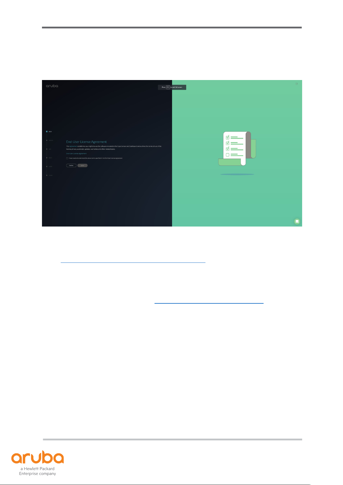
Figure 2.1 Configuration Wizard
For physical installation, status light information and FAQs please visit the following
page: https://capenetworks.com/guide#tabs-installation. The sensor can be plugged in
via an AC adapter provided or through PoE.
Wizard
Access the dashboard and login from https://dashboard.capenetworks.com
If the sensor is out of the box and has not been configured, you will be met with a
wizard. The wizard will assist you in setting up the sensor to connect to the network you
want to test. There is no captive portal configuration for the wizard, we will cover this
later in the document
Follow the wizard to set up the following initial configurations:
• SSID
• Network security
• Pre-configured external tests
• Users accessing the dashboard
In the event your sensor is not detected, you will be met with troubleshooting screens
to assist with getting your sensor online and connected to the dashboard.
UXI Quick Start Guide
May 2019
Settings
After you have gone through the wizard or have a sensor that has already gone
through the wizard, you are able to adjust the settings from the wizard and also
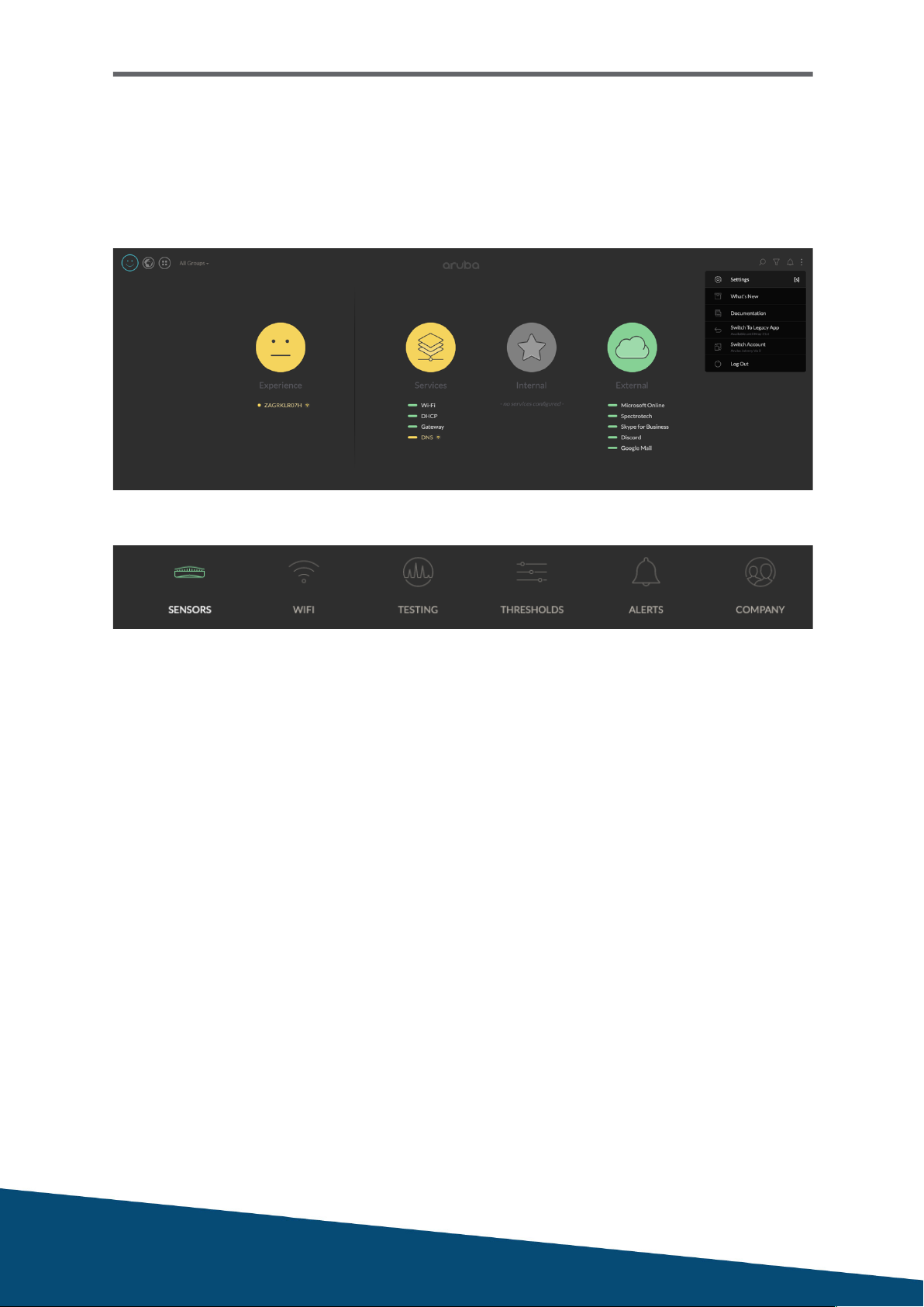
configure additional settings. You can access the settings via the hamburger menu via
the 3 dots on the top right as shown by Figure 2.2 or by pressing S.
Figure 2.2 Settings
Figure 2.3 Configurations
Figure 2.3 shows what can be configured, if you have been through the wizard, most
settings are configured for you. If the sensor has not been configured, you will need to
create an SSID for testing, associate the sensor to the SSID and configure testing
which is shown below.

UXI Quick Start Guide
May 2019
Group Management
In the event you have multiple sensors and they are getting difficult to manage
individually, you can create groups and assign sensors to the group.
1. In the settings menu, under Sensors, select the tab Group Management
2. Click on Add a group
3. Enter a name for the group
4. Click on Manage
5. Click on Add for the sensors you want in the group
6. Save
UXI Quick Start Guide
May 2019
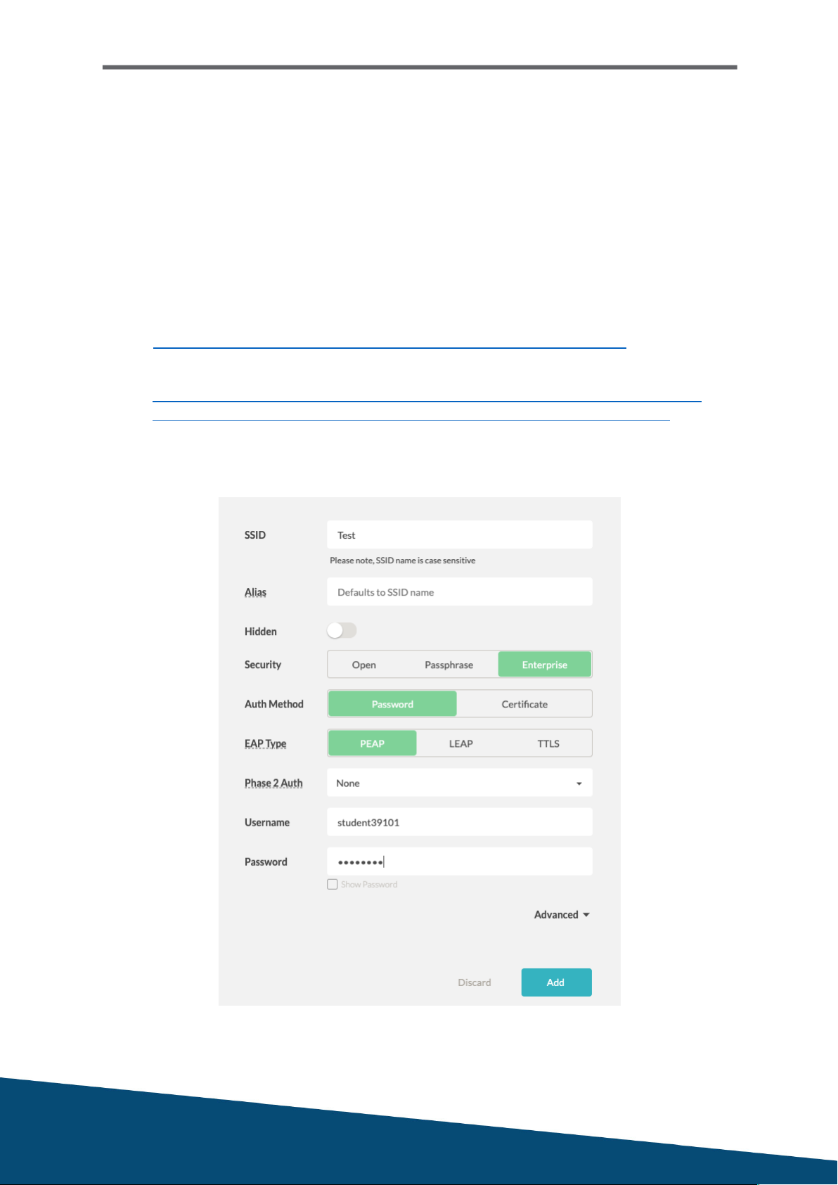
Adding an SSID
Similar to associating to an SSID for your devices with a few manual inputs. You can
add up to 3 SSIDs to test on one sensor.
1. When in the settings menu, go to Networks
2. Click Add SSID which will present you with a form as shown in Figure 2.4
3. Select SSID and choose user authentication method
a. If captive portal, choose open authentication and add the SSID
b. You will need to follow the instructions listed here:
https://help.capenetworks.com/captive-portal/captive-portal-setup
c. For EAP-TLS, please follow the guide linked below:
https://community.arubanetworks.com/t5/Cloud-Managed-Networks/How-to-
configure-Aruba-Service-Assurance-Cape-EAP-TLS/m-p/493252#M478
4. Advanced: If you would like to lock bands or have proxies
5. Save
Figure 2.4 SSID Configuration
UXI Quick Start Guide
May 2019
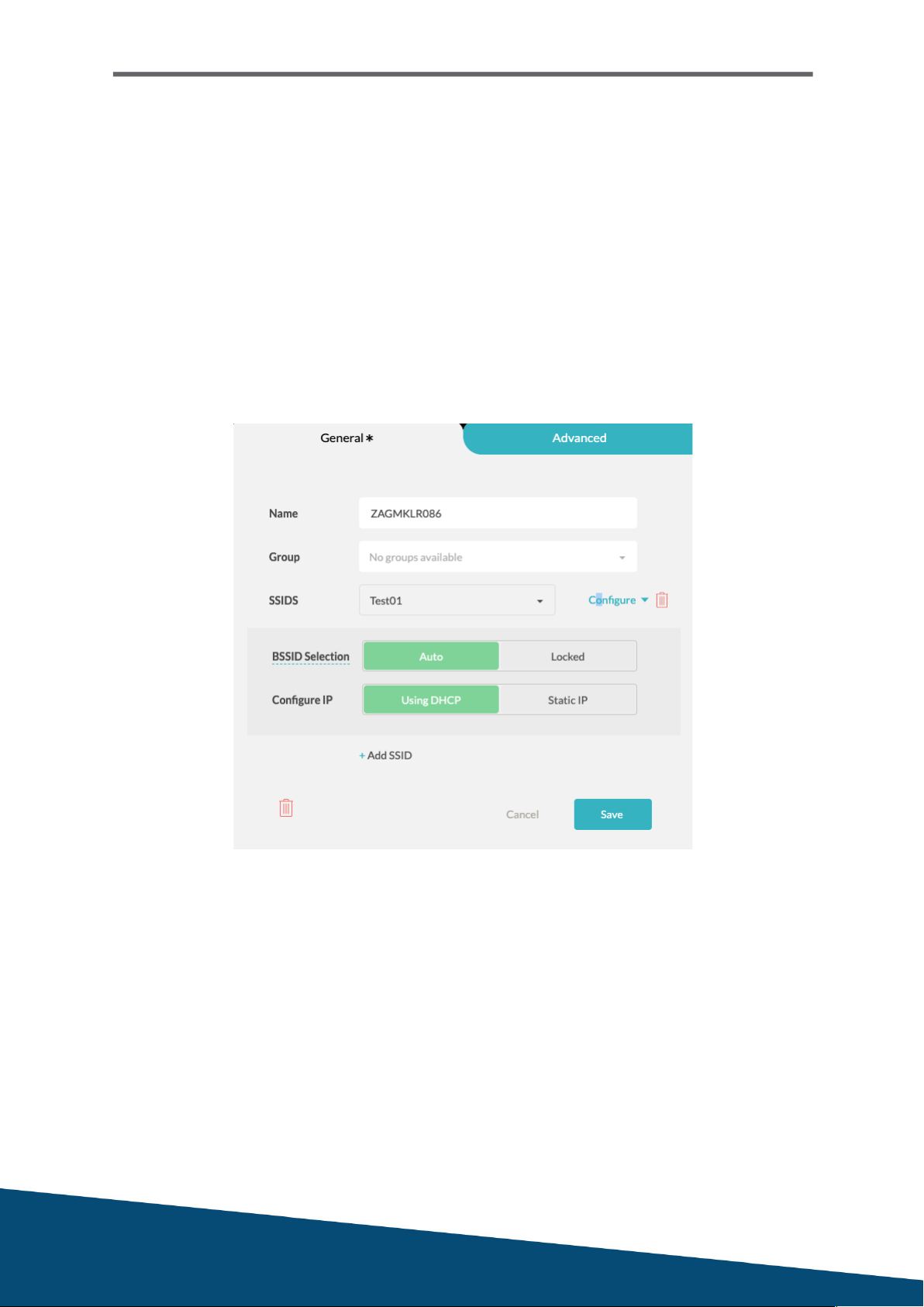
Associating to an SSID
We need to associate the SSID to sensor, you can associate up to 3 SSIDs per sensor.
1. When in the settings menu, go to Sensor and click on your sensor
2. Click on the pencil in line with the sensor to display the form as show in Figure 2.5
3. Click on the SSID drop down to select the SSID you want to test
4. Configure: If you would like to lock to an AP or want to assign a static IP
5. Add more SSIDs if you would have multiple SSIDs to test
5. Save
Figure 2.5 Sensor Configuration

UXI Quick Start Guide
May 2019
SSL Certificate Installation
Please note this is not needed if your environment does not secure or encrypt data
between your network and users.
If you are receiving an SSL error, please follow the instructions below.
To test HTTPS and not receive an SSL error message, you will have to install your SSL
certificate onto the sensor. The certificate will have to follow X.509 standards and can
be in the following formats: PEM, DER, PKCS#7 and PKCS#12.
Follow these steps to install the certificate onto the sensor:
1. Obtain your server certificate (from your firewall or Active Directory)
2. Find your sensor’s serial number under sensor details or via the box
3. Email support@capenetworks.com or open the chat popup
4. Attach the certificate you obtained in step 1
5. In the email or chat, include your company name and sensor serial number
Figure 2.6 Experience > Sensor > About or Settings > Sensor

UXI Quick Start Guide
May 2019
Creating Tests
Tests can be for internal services and also for external services such as websites.
1. When in the settings menu, go to Testing
2. Click on add test as shown in Figure 2.7
3. Choose either internal or external services
4. Predefined tests have been provided for common websites
Figure 2.8 shows a configuration for YouTube testing with Video Download
5. Custom tests are configured manually
6. Select a template and adjust settings if necessary
7. Click on Add to finish
Figure 2.7 Add test button
Figure 2.8 GUI for YouTube configuration

UXI Quick Start Guide
May 2019
ADVANCED TESTING
This section will discuss how to set up multiple SSIDs, threshold adjustments and
reviewing the WiFi data from the sensor.
Multiple SSIDs
Currently, the hardware will only let you test up to 3 SSIDs. Please note that the more
SSIDs, the sensor will have more to test and the more time it will spend testing across
the network.
You will first need to create the SSIDs you would like to test as explained under the
section “Adding an SSID” in the previous section.
After you have added your three SSIDs, you will need to associate them to the sensor.
1. Settings > Sensors > Click on the pencil next to your sensor
2. Click on Add SSID as shown in Figure 2.9
3. Select the SSID you want to add onto the sensor
4. Repeat until you have selected the desired number
Figure 3.1 Multiple SSID Configuration
UXI Quick Start Guide
May 2019
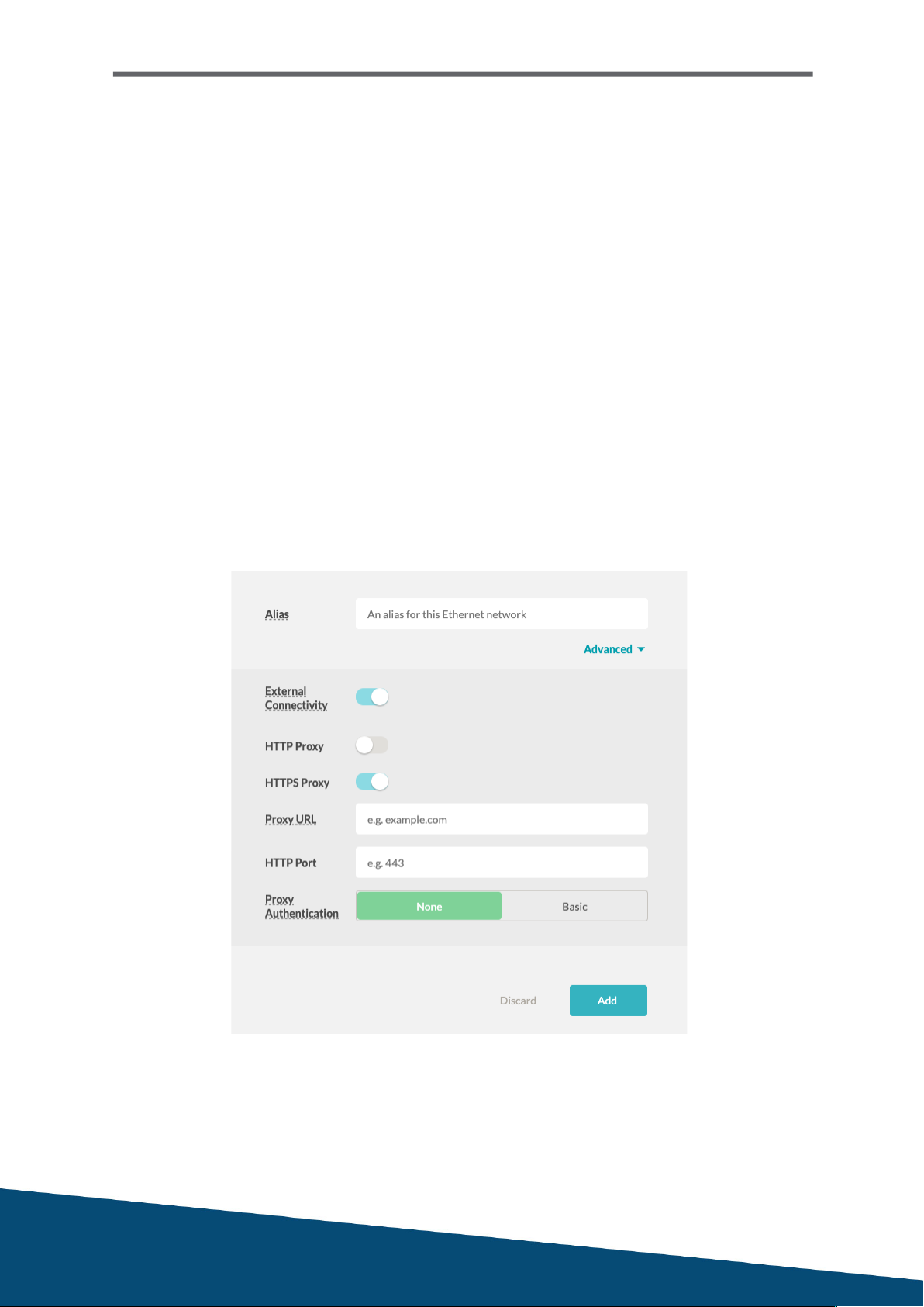
Setting up Ethernet testing
As of the 28th of May 2019, wired testing is now enabled once you create a wired
network configuration and associate the network to the sensor. The process is similar
to wireless testing.
1. When in the settings menu, go to Networks and click on the Wired tab
2. Click on Add Network
3. Create an alias for the wired network
4. Advanced: If you have proxy, this is where you can configure the details (Figure 3.2)
5. Click Add to save the network
6. Go to Sensor > Click on the pencil in line with the sensor you want to configure wired
7. Add wired network > Select the network you created in steps 1-5
8. Configure: If you would like to give the sensor a static wired IP address
9. Save
Figure 3.2 Create Wired Configurations

UXI Quick Start Guide
May 2019
BSSID Locking
When there is an access point you believe is having performance issues, the sensor is
able to lock onto the BSSID for testing.
1. When in the settings menu, go to Sensor and click on your sensor
2. Click on the pencil in line with the sensor
3. Next to your wireless network, click on configure (Figure 3.3)
4. Select “Locked” and then the AP MAC address you want to test
5. Optional: You can decide how long you want to test the SSID
6. Save the configuration
You can also lock BSSID via the sensor status page > “WiFi Environment” (Figure 3.4)
Figure 3.3 BSSID Locking

UXI Quick Start Guide
May 2019
Threshold Adjustments
After having the sensor for an extended period of time, you may want to adjust the
thresholds on your alerts to ensure that the sensor is showing more relevant issues.
1. When in the settings menu, go to Thresholds
2. Select a category of testing; WiFi, Network, Internal and External
3. Find the desired issue you want to adjust the thresholds for
4. Adjust conditions as required
5. Click on the floppy disk icon to save changes
6. You may also disable an alert if required
Figure 3.4 Adjusting threshold

UXI Quick Start Guide
May 2019
NAPLAN TESTING (AU)
This includes the NAPLAN test server, NAPLAN website and a simulated performance
test for bandwidth. You can find the test information here
https://help.capenetworks.com/testing/how-to-set-up-tests-for-the-naplan-system
NAPLAN website
Service category: External
Template Type: Custom
Test Template: Webserver
Title: NAPLAN Website
Target: www.nap.edu.au
Tests: HTTP on port 80, ICMP ping, HTTP status codes
NAPLAN test server latency
Service category: External
Template Type: Custom
Test Template: Webserver
Title: NAPLAN Latency
Target: pages.assessform.edu.au
Tests: HTTP on port 80, HTTPS on port 443, ICMP ping
Simulated bandwidth testing – Total of 3 bandwidth tests (Figure 3.1 and 3.2)
Service category: External
Template Type: Custom
Test Template: iPerf3
Title: NAPLAN Load
Target: 13.237.44.230
Direction: Download
Protocol: TCP
Port: 5001 / 5002 / 5003 (create a new test for each port)
Maximum bandwidth: 4Mbit/sec (can be adjusted)
Window size: 0
Test duration: 10 seconds
Parallel streams: 10
Frequency: 30 minutes

UXI Quick Start Guide
May 2019
Figure 3.2 Bandwidth Testing Configuration
NAPLAN Dashboard
End result should look something similar to Figure 3.1
Figure 3.1 NAPLAN Testing Dashboard

UXI Quick Start Guide
May 2019
Thank You for
Considering Aruba
Table of contents


 owner's manual")


