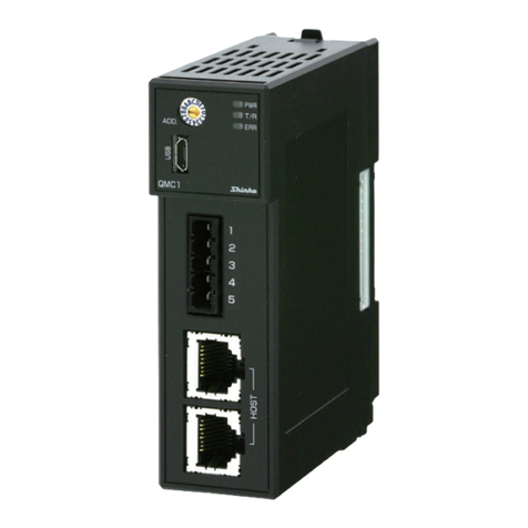
Shinko QMC1-MT User manual

Communication Expansion Module
QMC1-MT
INSTRUCTION MANUAL

ii

iii
Preface
Thank you for purchasing our communication expansion module [QMC1-MT] (hereinafter referred to as
this instrument or QMC1-MT).
This instruction manual (hereinafter referred to as this manual) describes the mounting method, functions,
operation method, and handling of this instrument.
Please read this manual carefully and fully understand it before using it.
Also, be sure to give this manual to users of this instrument to prevent accidents due to mishandling.
Notes
•This instrument should be used in accordance with the specifications described in the manual.
If it is not used according to the specifications, it may malfunction or cause a fire.
•Be sure to follow the warnings, cautions and notices. If they are not observed, serious injury or
malfunction may occur.
•The contents of this instruction manual are subject to change without notice.
•Care has been taken to ensure that the contents of this instruction manual are correct, but if there are
any doubts, mistakes or questions, please inform our sales department.
•This instrument is designed to be installed on a DIN rail within a control panel. If it is not, measures must
be taken to ensure that the operator does not touch power terminals or other high voltage sections.
•Any unauthorized transfer or copying of this document, in part or in whole, is prohibited.
•Shinko Technos Co., Ltd. is not liable for any damage or secondary damage(s) incurred as a result of
using this product, including any indirect damage.
SAFETY PRECAUTIONS
(Be sure to read these precautions before using our products.)
The safety precautions are classified into categories: “Warning” and “Caution”.
Depending on circumstances, procedures indicated by Caution may result in serious consequences, so
be sure to follow the directions for usage.
Warning
Procedures which may lead to dangerous conditions and cause death or
serious injury, if not carried out properly.
Caution
Procedures which may lead to dangerous conditions and cause superficial to
medium injury or physical damage or may degrade or damage the product, if
not carried out properly.
Warning
•To prevent an electrical shock or fire, only Shinko or qualified service personnel may handle the inner
assembly.
•To prevent an electrical shock, fire, or damage to instrument, parts replacement may only be
undertaken by Shinko or qualified service personnel.
Safety Precautions
•To ensure safe and correct use, thoroughly read and understand this manual before using this
instrument.
•This instrument is intended to be used for industrial machinery, machine tools and measuring
equipment. Verify correct usage after purpose-of-use consultation with our agency or main office.
(Never use this instrument for medical purposes with which human lives are involved.)
•External protection devices such as protective equipment against excessive temperature rise, etc.
must be installed, as malfunction of this product could result in serious damage to the system or injury
to personnel. Proper periodic maintenance is also required.
•This instrument must be used under the conditions and environment described in this manual.
Shinko Technos Co., Ltd. does not accept liability for any injury, loss of life or damage occurring due
to the instrument being used under conditions not otherwise stated in this manual.

iv
Warning on Model Label
Caution
Failure to handle this instrument properly may result in minor or moderate injury or property damage
due to fire, malfunction, malfunction, or electric shock. Please read this manual before using the product
to ensure that you fully understand the product.
Caution with Respect to Export Trade Control Ordinance
To avoid this instrument from being used as a component in, or as being utilized in the manufacture of
weapons of mass destruction (i.e. military applications, military equipment, etc.), please investigate the
end users and the final use of this instrument.
In the case of resale, ensure that this instrument is not illegally exported.
Precautions for Use
1. Installation Precautions
Caution
This instrument is intended to be used under the following environmental conditions (EN61010-1):
•Pollution degree 2
Ensure the mounting location corresponds to the following conditions:
•A minimum of dust, and an absence of corrosive gases
•No flammable, explosive gases
•No mechanical vibrations or shocks
•No exposure to direct sunlight, an ambient temperature of -10 to 50°C (14°F to 122°F) that does not
change rapidly, and no icing
•An ambient non-condensing humidity of 35 to 85 %RH
•No large capacity electromagnetic switches or cables through which large current is flowing
•No water, oil or chemicals or the vapors of these substances can come into direct contact with the unit.
•When installing this unit within a control panel, please note that ambient temperature of this unit – not
the ambient temperature of the control panel – must not exceed 50°C (122°F).
Otherwise the life of electronic components (especially electrolytic capacitor) may be shortened.
*Avoid setting this instrument directly on or near flammable material even though the case of this
instrument is made of flame-resistant resin.
2. Wiring Precautions
Caution
•Do not connect QTC1-2P (with power supply / communication option) (hereinafter referred to as
QTC1-2P) or QTC1-4P (with power supply / communication option) (hereinafter referred to as
QTC1-4P) in the same unit.
•When wiring, do not drop wire scraps into the ventilation window of this instrument.
It may cause fire or malfunction.
•When wiring, use a crimping pliers and a solderless terminal with an insulation sleeve in which an M3
screw fits.
•Tighten the terminal screw using the specified torque.
If excessive force is applied to the screw when tightening, the screw or case may be damaged.
•Do not pull or bend the lead wire with the terminal as the base point during or after wiring work.
It may cause malfunction.
•This instrument does not have a built-in power switch, circuit breaker and fuse.
It is necessary to install a power switch, circuit breaker and fuse near the instrument.
(Recommended fuse: Time-lag fuse, rated voltage 250 V AC, rated current 3 A)
•When wiring the power supply (24 VDC), do not confuse the polarities.
•Use a large wire (1.25 to 2.0 mm2) for the FG terminal.

v
3. Operation and Maintenance Precautions
Caution
•Do not touch live terminals. This may cause electrical shock or problems in operation.
•Turn the power supply to the instrument OFF when retightening the terminal or cleaning.
Working on or touching the terminal with the power switched ON may result in severe injury or death
due to electrical shock.
•Use a soft, dry cloth when cleaning the instrument.
(Alcohol based substances may tarnish or deface the unit.)
•As the display section is vulnerable, be careful not to put pressure on, scratch or strike it with a hard
object.
4. Compliance with Safety Standards
Caution
•Always install the recommended fuse described in this manual externally.
•Use of equipment in a manner not specified by the manufacturer may impair the protection provided
by the equipment.
•Use a device with reinforced insulation or double insulation for the external circuit connected to this
product.
•When using this product as a UL certified product, use a power supply conforming to Class 2 or LIM
for the external circuit connected to the product.
The following abbreviations are used in the text, figures, and tables of this manual.
Symbol
Term
PV
Process variable (PV)
SV
Desired value (SV)
MV
Output manipulated variable (MV)
AT
Auto-tuning (AT)
CT
Current transformer (CT) [for heater burnout alarm (option)]
About description of reference page
In the case of "Refer to page 2-2.", it is described as (P. 2-2).

vi
Contents
1Overview .........................................................................................1-1
1.1 Overview of QMC1-MT.................................................................................................1-1
1.2 Description of Module...................................................................................................1-2
1.3 System Configuration ...................................................................................................1-3
1.3.1 Ethernet Communication with Host Computer [Console Selection (MODBUS/TCP)]................1-3
1.3.2 Ethernet Communication with PLC [Console Selection (SLMP ASCII or SLMP BINARY)] .......1-4
1.4 Exchange of Parameters ..............................................................................................1-5
2Model ..............................................................................................2-1
2.1 Model............................................................................................................................2-1
2.2 How to Read the Model Label ......................................................................................2-1
3Name and Functions .......................................................................3-1
4Procedure Before Starting Operation..............................................4-1
5Setting of QMC1-MT IP Address.....................................................5-1
6Setting of Specification....................................................................6-1
6.1 Preparation...................................................................................................................6-1
6.1.1 Preparation of USB Communication Cable and Console Software............................................6-1
6.1.2 Connecting to Host Computer.....................................................................................................6-1
6.2 Specification Setting .....................................................................................................6-4
6.2.1 USB Limited Item Setting ............................................................................................................6-6
6.2.2 Setting Event Input / Output Items ..............................................................................................6-9
6.2.3 Selecting Setting Value Reload Request ..................................................................................6-10
6.2.4 Reading Monitor Values ............................................................................................................6-11
7Mounting .........................................................................................7-1
7.1 Selection of Location....................................................................................................7-2
7.2 External Dimensions (Unit: mm)...................................................................................7-2
7.3 Mounting.......................................................................................................................7-3
8Wiring..............................................................................................8-1
8.1 Recommended Terminal..............................................................................................8-1
8.2 Pin Assignment and Terminal Arrangement ..................................................................8-2
8.2.1 Pin Assignment of Ethernet Communication Connector.............................................................8-2
8.2.2 Power supply terminal and FG terminal arrangement ................................................................8-2
8.3 Wiring ...........................................................................................................................8-3
8.3.1 Wiring for power supply and FG..................................................................................................8-3
8.4 Connect to Ethernet......................................................................................................8-5
8.4.1 Example 1 of Connection to Ethernet .........................................................................................8-5
8.4.2 Example 2 of Connection to Ethernet .........................................................................................8-6
9MODBUS/TCP Protocol ..................................................................9-1

vii
9.1 Communication Procedure...........................................................................................9-1
9.2 Port Number .................................................................................................................9-2
9.3 Message Format...........................................................................................................9-2
9.4 Message Example ........................................................................................................9-4
10 Communication Command List .....................................................10-1
10.1 List of QMC1-MT Communication Commands (For Console Software) .....................10-1
10.2 List of QMC1-MT Communication Commands (For Communication Program) ..........10-3
10.3 List of Communication Commands for Modules Connected to QMC1-MT .................10-9
10.4 Data..........................................................................................................................10-88
10.4.1 Notes About Write/Read Command ........................................................................................10-88
10.4.2 Write Command.......................................................................................................................10-88
10.4.3 Read Command ......................................................................................................................10-88
10.5 Negative Acknowledgement .....................................................................................10-89
10.5.1 Error Code 2 (02H)..................................................................................................................10-89
10.5.2 Error Code 3(03H)...................................................................................................................10-89
10.5.3 Error Code 17(11H) .................................................................................................................10-89
10.6 Notes on Programming Monitoring Software............................................................10-89
10.6.1 How to Speed up the Scan Time.............................................................................................10-89
10.6.2 How to Read PID Parameters after AT or Start-up AT Finishes .............................................10-89
10.6.3 Notes on Batch Transmission of All Setting Values ................................................................10-89
10.7 Initialization Items by Changing Settings ..................................................................10-90
11 Operation ......................................................................................11-1
11.1 Control Permission .....................................................................................................11-1
11.2 Set PID Constants (Execute AT).................................................................................11-3
11.3 Set Alarm....................................................................................................................11-5
12 Communication with PLC Using SIF Function ..............................12-1
12.1 Procedure Before Starting Operation .........................................................................12-2
12.2 Setting of QMC1-MT IP Address ................................................................................12-3
12.3 Setting Specification of QMC1-MT .............................................................................12-4
12.3.1 Preparation of USB Communication Cable and Console Software..........................................12-4
12.3.2 Connecting to Host Computer...................................................................................................12-4
12.3.3 Specification Settings for QMC1-MT.........................................................................................12-7
12.4 Mounting of QMC1-MT .............................................................................................12-28
12.5 Wiring of QMC1-MT..................................................................................................12-31
12.5.1 Wiring for Power Supply..........................................................................................................12-31
12.6 Communication with Mitsubishi Electric Corporation PLC ........................................12-33
12.6.1 Communication parameter setting ..........................................................................................12-33
12.6.2 Connect to Ethernet ................................................................................................................12-37
12.6.3 Communication Procedure......................................................................................................12-38
12.6.4 Handshake between QMC1-MT and PLC ..............................................................................12-39
12.6.5 PLC communication data map ................................................................................................12-41
12.6.6 Exchange of data between QMC1-MT and PLC ....................................................................12-50
12.6.7 Data Settings...........................................................................................................................12-51

viii
13 Specifications ................................................................................13-1
13.1 Standard Specifications..............................................................................................13-1
14 Troubleshooting ............................................................................14-1
14.1 Operation indicator .....................................................................................................14-1
14.2 Communication...........................................................................................................14-2
14.3 Status Flag .................................................................................................................14-2

1-1
1 Overview
1.1 Overview of QMC1-MT
This instrument is a communication expansion module that connects to the control module (QTC1-) for
Ethernet communication.
A maximum of 16 control modules QTC1-20 (no power supply / communication option) (hereinafter
referred to as QTC1-20) or QTC1-40 (no power supply / communication option) (hereinafter referred to
as QTC1-40) can be connected via BUS, and a maximum of 64 points can be controlled.
Connection example of QMC1-MT and QTC1-40
(Fig. 1.1-1)
Ethernet
Host computer or
PLC
Maximum of 16 modules
Control module QTC1-40
(no power supply / communication
option)
Communication expansion module
QMC1-MT

1-2
1.2 Description of Module
(Fig. 1.2-1)
This instrument is the communication expansion module for
communication translation and data management.
Connects to control module (QTC1-) for Ethernet communication
(MODBUS/TCP or SIF function).
MODBUS/TCP
Physical layer: 10BASE-T/100BASE-TX automatic recognition
User layer: MODBUS/TCP Number of connections: 1
SIF function
The SIF function (Smart InterFace, programless communication
function) enables programless connection to the PLC.
User layer:TCP/IP
Mitsubishi Electric Corporation PLC MELSEC
Communication Protocol
Frame: QnA compatible 3E frame (SLMP 3E frame)
Code: Binary or ASCII
Connectable PLC: 1 unit

1-3
1.3 System Configuration
Caution
Do not connect QTC1-2P or QTC1-4P in the same unit.
1.3.1 Ethernet Communication with Host Computer [Console Selection (MODBUS/TCP)]
A maximum of 16 control modules QTC1-20 (no power supply / communication option) (hereinafter
referred to as QTC1-20) or QTC1-40 (no power supply / communication option) (hereinafter referred
to as QTC1-40) can be connected via BUS, and a maximum of 64 points can be controlled.
Connection example of QMC1-MT and QTC1-40
(Fig. 1.3.1-1)
Ethernet
Host computer or
PLC
Maximum of 16 modules
Control module QTC1-40
(no power supply / communication
option)
Communication expansion module
QMC1-MT

1-4
1.3.2 Ethernet Communication with PLC [Console Selection (SLMP ASCII or SLMP BINARY)]
Program less connection to Mitsubishi Electric Corporation PLC MELSEC is possible.
A maximum of 16 control modules QTC1-20 (no power supply / communication option) (hereinafter
referred to as QTC1-20) or QTC1-40 (no power supply / communication option) (hereinafter referred
to as QTC1-40) can be connected via BUS, and a maximum of 64 points can be controlled.
Connection example of QMC1-MT and QTC1-40
(Fig. 1.3.2-1)
Ethernet
Maximum of 16 modules
Control module QTC1-40
(no power supply / communication
option)
Communication expansion module
QMC1-MT
PLC

1-5
1.4 Exchange of Parameters
The parameter exchange is shown in the figure below.
For RO (read only)
(Fig. 1.4-1)
For R/W (read and write)
(Fig. 1.4-2)
QMC1-MT
(2) Receives sending
data from the
host computer.
(3) Returns response
data to the host
computer.
(4) Monitor the
control module
QTC1-0.
Host computer
(1) Monitor the
control module.
QTC1- 0
(5) Receives the
sending data
from the
QMC1-MT.
(6) Returns
response data to
the QMC1-MT.
Asynchronous
QMC1-MT
(2) Receives sending
data from the host
computer.
(3) Returns response
data to the host
computer.
(4) Set and monitor
the control module
QTC1-0.
Host computer
(1) Set and monitor
the control
module.
QTC1- 0
(5) Receives the
sending data from
the QMC1-MT
and controls it.
(6) Returns response
data to the
QMC1-MT.
Synchronous

2-1
2 Model
2.1 Model
QMC1-MT
2.2 How to Read the Model Label
The model label is attached to the right side of this instrument.
(Fig. 2.2-1)
Model
Power supply voltage, power consumption
Serial number

3-1
3 Name and Functions
(Fig. 3-1)
Base

3-2
Operation indicator
No.
Symbol (color)
Name and Function
PWR (Green)
Power indicator (*1)
•Lights off (always): No power supply to the instrument.
•Lights up (always): Power supply to the instrument.
•Flashing (500 ms lights up/500 ms lights off):
Non-volatile IC memory error.
T/R (Yellow)
Communication indicator (*1)
•Lights off (always): Ethernet communication error (no response) or USB
communication.
•Flashing (slow): Ethernet communication error (reception error).
•Flashing (fast): Ethernet communication is normal.
ALM (Red)
Alarm indicator (*1)
•Lights up (1 sec.): When communication with the slave [control module
(QTC1-)] is error. (*2)
•Flashing (250 ms lights up/250 ms lights off):
When power is supplied from a PC via USB.
LA1 (Yellow)
Link indicator (LA1)
•Lights up (always): When link is established.
•Lights off (always): When link is not established.
LA2 (Yellow)
Link indicator (LA2)
•Always lights off
RUN (Green)
Line connection indicator (*1)
•Lights up: When Ethernet connection.
ERR (Red)
Communication error indicator (*1)
•Lights off (always): No errors.
•Lights up (1 sec.): When communication error occurs in SLMP
communication (*3) of Ethernet.
(e.g.) When data outside the setting range is sent from the PLC
The ERR indicator lights up for 1 second in response to a
negative-acknowledgement from the connected module.
(*1): Each operation indicator (except LA1 and LA2) lights up sequentially during warm-up after
power-on.
(*2): Does not light up in the SIF function.
(*3) Communication protocol for Mitsubishi Electric Corporation PLC MELSEC.

3-3
Switch and connector
No.
Symbol
Name and Function
USB
Console communication connector
Connector for console communication tool cable.
IP ADDRESS
QMC1-MT IP address setting rotary switch
Ethernet
Ethernet communication connector [Modular jack (RJ45)]
DIP switch
Not used in this instrument. Please leave all switches OFF.
Connector
Connector for connection to control module QTC1-0.
Lock lever
Lever for fixing or releasing when mounting or dismounting on a DIN rail.

4-1
4 Procedure Before Starting Operation
The flow up to the operation in case of Ethernet communication with the host computer is shown below.
Preparation of
communication program
Communication program is required for Ethernet communication with
the host computer.
Refer to “9 MODBUS/TCP Protocol” (P.9-1), to create the
communication program.
Setting of QMC1-MT
IP address
Set the QMC1-MT IP address.
Refer to “5 Setting of QMC1-MT IP Address” (P. 5-1).
Setting of specification
Set the items of through USB.
Refer to “6.2 Specification Setting” (P. 6-4).
Mounting
Mount the QMC1-MT to the DIN rail.
Refer to “7.3 Mounting” (P. 7-3).
Wiring
Wire the QMC1-MT.
Refer to “8.3 Wiring” (P. 8-3).
Connect to Ethernet
Connect the host computer and QMC1-MT to Ethernet.
Refer to “8.4 Connect to Ethernet” (P. 8-5).
Setting of
control parameters
Set QTC1-0 control parameters such as SV and alarm.
Refer to “10 Communication Command List” (P. 10-1).
Operation start
Send the control enable command and start operation.
Refer to “11 Operation” (P. 11-1).
(Fig. 4-1)

5-1
5 Setting of QMC1-MT IP Address
Caution
•The QMC1-MT IP address setting is required for Ethernet communication.
Selection of QTC1-20 or QTC1-40 module address is required to communicate with QMC1-MT.
•If the QMC1-MT IP address setting has been changed, turn the power OFF and ON.
The QMC1-MT IP address setting becomes effective by turning the power OFF and ON.
The 3rd (a) and 4th (b) bytes of the QMC1-MT IP address (e.g. 192.168.a.b) are set using the QMC1-MT
IP address setting rotary switch or console software.
The factory default for the QMC1-MT IP address is 192.168.0.0.
When using the QMC1-MT IP address setting rotary switch
Use a small flat-blade screwdriver to set the QMC1-MT IP address.
(Fig. 12.2-1)
Rotary switch
Description and Setting range
Factory default
3rd octet
QMC1-MT IP address 3rd byte setting
Setting range: 0 to 15 (0 to F)
0
4th octet
QMC1-MT IP address 4th byte setting
Setting range: 0 to 255(0 to FF)
0
When using the console software
When the 4th octet of the rotary switch for setting the QMC1-MT IP address is set to "0," the setting
values of the 3rd and 4th bytes of the console software set using USB communication become
effective.
If necessary, set the 1st byte (192) and the 2nd byte (168). Refer to "6. Setting of Specification"
(P.6-1) for details.
QMC1-MT IP address
setting rotary switch

6-1
6 Setting of Specification
Set the specifications.
This section describes how to set specifications using console software (SWC-QMC101M).
6.1 Preparation
6.1.1 Preparation of USB Communication Cable and Console Software
Please prepare the USB communication cable and the console software.
•USB communication cable
USB-micro USB Type-B (commercial item)
•Console software (SWC-QMC101M)
Please download from our website and install.
Click https://shinko-technos.co.jp/e/ → Support/Download → Software
6.1.2 Connecting to Host Computer
Caution
Disconnect the Ethernet cable (LAN cable) from the Ethernet communication connector when
communicating by connecting the USB communication cable.
(1) Connect the micro USB Type-B side of the USB communication cable to the console
communication connector of this instrument.
(2) Connect the USB plug of the USB communication cable to the USB port of the host computer.
Connection example of QMC1-MT and QTC1-40
(Fig. 6.1.2-1)
Host computer
USB port
USB communication cable
(commercial item)
USB - micro USB Type-B
Communication
expansion module
QMC1-MT
Console communication
connector
Table of contents
Other Shinko Control Unit manuals
Popular Control Unit manuals by other brands

SPX FLOW
SPX FLOW POWER TEAM A operating instructions
AutomationDirect
AutomationDirect CLICK C0-08TR-3 manual
Keyautomation
Keyautomation 14A Instructions and warnings for installation and use
SimTech
SimTech SIMCom SIM7600E-PCIE Hardware design
Blu Stream
Blu Stream Multicast ACM200 user manual

Technica Engineering
Technica Engineering TE-1437 user manual

Hi-P
Hi-P HIP-10RV Maintenance instructions

Sun Power
Sun Power E Series Safety and installation instructions

Oriental motor
Oriental motor ASTEP AR Series operating manual

Timeguard
Timeguard TS800B operating instructions

red lion
red lion ITMA product manual
Krom Schroder
Krom Schroder VAS Series operating instructions
