TESTO 0554 9311 01 User manual

LAN/PoE communication module
0554 9330
WLAN communication module
0554 9320
testo UltraRange communication module
0554 9311 01 / 0554 9311 02
0554 9312 01 / 0554 9312 02
0554 9313 01 / 0554 9313 02
0554 9314 01 / 0554 9314 02
Instruction manual

Contents
Contents
1About this document ...........................................................................3
2Safety and disposal..............................................................................4
3Product-specific approvals .................................................................4
4Support .................................................................................................4
5Lieferumfang.........................................................................................4
6LAN/PoE communication module.......................................................4
6.1 Use........................................................................................................................ 4
6.2 Product description ............................................................................................... 4
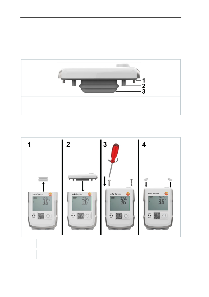
6.3 Commissioning ..................................................................................................... 5
6.4 Technical data for the LAN/PoE communication module...................................... 6
7WLAN communication module ...........................................................6
7.1 Use........................................................................................................................ 6
7.2 Product description ............................................................................................... 7
7.3 Commissioning ..................................................................................................... 7
7.4 Technical data for WLAN module .........................................................................8
8testo UltraRange communication module .........................................8
8.1 Use........................................................................................................................ 8
8.2 Product description ............................................................................................... 9
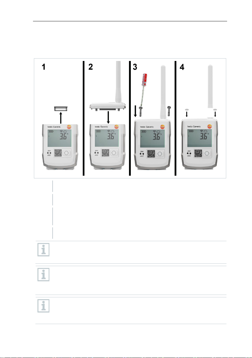
8.3 Commissioning ................................................................................................... 10
8.4 Technical data for the testo UltraRange communication module .......................11
9Maintenance .......................................................................................12
9.1 Cleaning the housing .......................................................................................... 12

1 About this document
3
1About this document
•The instruction manual is an integral part of the testo Saveris measurement
data monitoring system.
•Keep this documentation to hand so that you can refer to it when necessary.
•Please read this instruction manual through carefully and familiarize yourself
with the product before putting it to use.
•Hand this instruction manual on to any subsequent users of the product.
•The instruction manual for the testo Saveris measurement data monitoring
system is divided into the following sub-documents:
oOperating instructions for the testo Saveris measurement data
monitoring system
oCommissioning instructions for the testo Saveris measurement data
monitoring system
oOperating instructions for individual system components
•Pay particular attention to the safety instructions and warning advice in order
to prevent injury and damage to the product.
•Familiarity with a PC as well as the Microsoft®products is assumed in this
documentation.
Symbols and writing standards
Display Explanation
Note: basic or further information.
1. ...
2. ...
Action: several steps, the sequence must be followed.
•…
List
> ... Action: one step or optional step.
- ...
Result of an action.
✓…
Requirement
1...
2...
Position numbers for the clarification of the relationship
between text and picture.
Menu
Elements of the instrument, the instrument display or the
program interface.
[OK]
Control keys of the instrument or buttons of the program
interface.

2Safety and disposal
4
Display Explanation
... | ...
Functions/paths within a menu.
“...” Example entries
2Safety and disposal
Take the testo information document into account (accompanies the product).
3Product-specific approvals
Please find the current country approvals in the enclosed Approvals and
Certifications document.
4Support
You can find up-to-date information on products, downloads and links to contact
addresses for support queries on the Testo website at: www.testo.com.
5Lieferumfang
•Communication module
•Instruction manual
•Testo information
•Approvals and Certifications
6LAN/PoE1communication module
6.1 Use
The LAN/PoE communication module for the testo 150 data logger module is
designed to transmit measurement data and to supply power via a LAN
infrastructure. The product is used in the monitoring of products subject to cold
chain requirements in warehouses, production facilities, cold rooms, clinics,
laboratories and laboratory equipment.
The product can only be used with other Testo components. Use of the product
requires skilled personnel trained in the above areas.
If the network ports used are PoE-enabled, power can be supplied to a
connected testo 150 data logger module via the Ethernet cable.
6.2 Product description
Overview
1Power over Ethernet

7WLAN communication module
6
2
Place the communication module on the testo 150 data logger module.
3
Attach the communication module to the testo 150 data logger module
using the screws.
4
Close screw openings with rubber plugs.
It is not possible to replace communication modules while the testo 150
data logger module is in operation!
To replace a communication module, the power supply must be
disconnected (remove batteries/pull out mains plug).
Once the communication modules have been installed, the testo 150
data logger module can be returned to its original packaging.
6.4 Technical data for the LAN/PoE
communication module
PoE performance class 0 max. 7 W
Feature Value
Order no.
0554 9330
Connections
TCI
LAN/PoE
Dimensions (W x H x L)
69.3 x 17.7 x 29.0 mm
Weight
Approx. 45 g
Protection class
IP30 with mounted testo 150 data logger
module
Housing material
PC/PET (front); ABS+PC+10% GF/PET (rear)
Communication cycle
5 seconds - 24 hours
Storage temperature
-35 °C to 60 °C
Operating temperature
-35 °C to 50 °C
7WLAN communication module
7.1 Use
The WLAN communication module for the testo 150 data logger module is
designed for the wireless transmission of measurement data. The product is
used in the monitoring of products subject to cold chain requirements in
warehouses, production facilities, cold rooms, clinics, laboratories and
laboratory equipment.

7 WLAN communication module
7
The product can only be used with other Testo components. Use of the product
requires skilled personnel trained in the above areas.
7.2 Product description
Overview
1
Fastening screws
2
Positioning aid
3
TCI connector
7.3 Commissioning
Attaching the communication module
1
Remove the protective cap.
2
Place the communication module on the testo 150 data logger module.

8testo UltraRange communication module
8
3
Attach the communication module to the testo 150 data logger module
using the screws.
4
Close screw openings with rubber plugs.
It is not possible to replace communication modules while the testo 150
data logger module is in operation!
To replace a communication module, the power supply must be
disconnected (remove batteries/pull out mains plug).
Once the communication modules have been installed, the testo 150
data logger module can be returned to its original packaging.
Rücksprache PM:
weitere Infobox:
Intern verbaute Batterien werden nicht geladen, bei Ausfall der
externen Versorgung misst der Logger bei 15 min Mess- und
Kommunikationstakt noch ca ... und schaltet dann in Sleepmode.
7.4 Technical data for WLAN module
Feature Value
Order no.
0554 9320
Connections
TCI
Dimensions (W x H x L)
69.3 x 9.5 x 29.0 mm
Weight
Approx. 17 g
Protection class
IP67 with mounted testo 150 data logger
module
Housing material
PC/PET (front); ABS+PC+10% GF/PET (rear)
Communication cycle
1 min to 24 h
Storage temperature
-35 °C to 60 °C
Operating temperature
-35 °C to 50 °C
8testo UltraRange communication
module
8.1 Use
A testo UltraRange communication module with testo UltraRange radio
technology is designed for the wireless transmission of measurement data.

8 testo UltraRange communication module
9
UltraRange communication modules are designed either for combination with
testo 150 data logger modules or with the UltraRange Gateway.
Use of the product requires skilled personnel trained in the above areas.
An UltraRange Gateway is required to transmit data to the Saveris base
when testo 150 data logger modules are combined with UltraRange
communication modules.
Select the appropriate regional version of the testo UltraRange
communication module depending on the intended region of use.
Products of this type are generally not suitable for outdoor use when
delivered. Prerequisite for outdoor use are measures that reliably
protect the product from environmental influences (e.g. moisture, solar
radiation). Please note that measures to protect the product from
environmental influences may impair its performance.
8.2 Product description
Overview
1
Radio antenna
2
Fastening screws
3
Positioning aid
4
TCI connector

8testo UltraRange communication module
10
8.3 Commissioning
Attaching the communication module
1
Remove the protective cap.
2
Place the communication module on the testo 150 data logger module.
3
Attach the communication module to the testo 150 data logger module
using the screws.
4
Close screw openings with rubber plugs.
When using wireless modules with external antenna, please ensure that
the screw connection between antenna and module has been
tightened.
It is not
possible to replace communication modules while the testo 150
data logger module is in operation!
To replace a communication module, the power supply must be
disconnected (remove batteries/pull out mains plug).
Once the communication modules have been installed, the testo 150
data logger module can be returned to its original packaging. To place
testo 150 data logger modules with mounted UltraRange module in the
packaging, unscrew the external antenna and place in the recess

8 testo UltraRange communication module
11
provided in the packaging, underneath the testo 150 data logger
module.
8.4 Technical data for the testo UltraRange
communication module
Feature Value
Order no.
0554 9311 01 (Region EU, testo 150
data logger module)
0554 9311 02 (Region EU, UltraRange
Gateway)
0554 9312 01 (Region US, testo 150
data logger module)
0554 9312 02 (Region US, UltraRange
Gateway)
0554 9313 01 (Region CN, testo 150
data logger module)
0554 9313 02 (Region CN, UltraRange
Gateway)
0554 9314 01 (Region JP, testo 150
data logger module)
0554 9314 02 (Region JP, UltraRange
Gateway)
Connections
TCI
1
Dimensions (W x H x L)
69.3 x 9.5 x 28.9 mm (without antenna)
Antenna length
90 mm
Weight
Approx. 31 g
Protection class
IP67 with mounted testo 150 data logger
Housing material
ABS+PC+10% GF/PET
Radio frequency
testo UltraRange
communication module
- Region: EU
- Region: US
- Region: CN 868
- Region: JP 920
868 MHz
915 MHz
868 MHz
920 MHz
Wireless range
>100 m indoors
Communication cycle 1 min - 24 hours service life to be expected
with standard parameters
Storage temperature
-40 °C to 60 °C
Operating temperature
-40 °C to 50 °C

9Maintenance
12
9Maintenance
9.1 Cleaning the housing
>
If the housing is dirty, clean it with a damp cloth.
Use distilled water, or alternatively mild solvents, such as
isopropanol. If
using isopropanol, please refer to the instruction leaflet for the product.
Isopropanol fumes have a slight narcotic effect, and typically cause
irritation of the eyes and sensitive mucous membranes. When using it,
please ensure that there is adequate ventilation.
The use of strong or harsh alcohol may result in damage to the
instrument.
1
Moisten a microfibre cloth with 70% isopropanol.
2
Clean the data logger and wall bracket.
Other tolerated reagents for cleaning:
Active substances/additives Maximum concentration
Pentapotassium bis(peroxymonosulphate)
bis(sulphate)
1% (%V/V)
Peracetic acid, acetic acid
3% (%V/V)
Glutaraldehyde
3% (%V/V)
Quaternary ammonium cations/compounds
1.5% (%V/V)
Sodium hydroxide
3% (%V/V)
Isopropanol
70% (%V/V)
Ethanol
80% (%V/V)
H2O2
35% (m%)
% V/V = volume percent
m % = mass fraction

Testo SE & Co. KGaA
Testo-Strasse 1
D-79853 Lenzkirch
Germany
Phone: +49 7653 681-0
Fax: +49 7653 681-7699
Email: [email protected]e
www.testo.com
0970 2814 en 01

Approval and Certification
Product 0554 9320
(WLAN communication module)
Mat.-No. 0554 9320
Model No. 0554 9320
Date 26.11.2019
The use of the wireless module is subject to the regulations
and stipulations of the respective country of use, and the module
may only be used in countries for which a country certification has
been granted. The user and every owner has the obligation to
adhere to these regulations and prerequisites for use, and
acknowledges that the re-sale, export, import etc. in particular in
countries without wireless permits, is his responsibility.
Country Comments
Australia
New Zealand E1561
Canada Contains IC: 451I-CC3120MOD
IC: 6127B-05549320
See IC Warnings
Europa + EFTA
The EU Declaration of Conformity
can be found on the testo
homepage www.testo.com under
the product specific downloads.
EU countries:
Belgium (BE), Bulgaria (BG), Denmark
(DK), Germany (DE), Estonia (EE), Finland
(FI), France (FR), Greece (GR), Ireland (IE),
Italy (IT), Latvia (LV), Lithuania (LT),
Luxembourg (LU), Malta (MT),
Netherlands (NL), Austria (AT), Poland
(PL), Portugal (PT), Romania (RO), Sweden
(SE), Slovakia (SK), Slovenia (SI), Spain
(ES), Czech Republic (CZ), Hungary (HU),
United Kingdom (GB), Republic of Cyprus
(CY).
EFTA countries:
Iceland, Liechtenstein, Norway,
Switzerland
WEEE Reg. no. DE
75334352
Japan
See Japan Information
Turkey Authorized
USA Contains FCC ID: Z64-CC3120MOD
FCC ID: WAF-05549320
See FCC Warnings
WLAN-module Feature Values
Radio range > 100 m (free field)
WLAN Type CC3120MODRNM
MOBR
Company Texas Instruments
WLAN radio
class Accord with the standard
of IEEE 802.11b/g/n
RF Band 2412-2472MHz
Output
power 15.64dBm
Antenna gain 0.6dbi

IC Warnings
RSS‐Gen & RSS‐247 statement:
This device complies with Industry Canada licence‐exempt RSS
standard(s).
Operation is subject to the following two conditions:
(1) this device may not cause interference, and
(2) this device must accept any interference, including interference that
may cause undesired operation of the device.
Le présent appareil est conforme aux CNR d'Industrie Canada applicables
aux appareils radio exempts de licence.
L'exploitation est autorisée aux deux conditions suivantes :
(1) l'appareil ne doit pas produire de brouillage, et
(2) l'utilisateur de l'appareil doit accepter tout brouillage
radioélectrique subi, même si le brouillage est susceptible d'en
compromettre le fonctionnement.
Caution: Radio Frequency Radiation Exposure
This equipment complies with IC radiation exposure limits set forth for
an uncontrolled environment and meets the IC radio frequency (RF)
Exposure Guidelines.
Co‐Location:
This transmitter must not be co‐located or operated in conjunction with
any other antenna or transmitter.
Attention : exposition au rayonnement de radiofréquences
Cet équipement est conforme aux limites d'exposition aux
radiofréquences IC fixées pour un environnement non contrôlé et aux
Lignes directrices relatives à l'exposition aux radiofréquences (RF).
Co‐location
Ce transmetteur ne peut pas être installé en colocation ou être utilisé
avec une autre antenne ou transmetteur, quel qu'en soit le type.
FCC Warnings
Information from the FCC (Federal Communications Commission)
For your own safety
Shielded cables should be used for a composite interface. This is to
ensure continued protection against radio frequency interference.
FCC warning statement
This equipment has been tested and found to comply with the limits for
a Class B digital device, pursuant to Part 15 of the FCC Rules. These limits
are designed to provide reasonable protection against harmful
interference in a residential installation. This equipment generates, uses
and can radiate radio frequency energy and, if not installed and used in
accordance with the instructions, may cause harmful interference to
radio communications. However, there is no guarantee that interference
will not occur in a particular installation. If this equipment does cause
harmful interference to radio or television reception, which can be
determined by turning the equipment off and on, the user is encouraged
to try to correct the interference by one or more of the following
measures:
• Reorient or relocate the receiving antenna.
• Increase the separation between the equipment and receiver.
• Connect the equipment into an outlet on a circuit different from that
to which the receiver is connected.
• Consult the dealer or an experienced radio/TV technician for help.
Caution
Changes or modifications not expressly approved by the party
responsible for compliance could void the user's authority to operate the
equipment. Shielded interface cable must be used in order to comply
with the emission limits.
Warning
This device complies with Part 15 of the FCC Rules.
Operation is subject to the following two conditions:
(1) this device may not cause harmful interference, and
(2) this device must accept any interference received,
including interference that may cause undesired operation.
Caution: Radio Frequency Radiation Exposure
RF exposure information: To maintain compliance with FCC RF exposure
requirements, use the product that maintain a 20cm separation distance
between the user's body and the host. It satisfies RF exposure
compliance of FCC.
Co‐Location:
This transmitter must not be co‐located or operated in conjunction with
any other antenna or transmitter.
Japan Information
当該機器には電波法に基づく、技術基準適合証
明等を受けた特定無線設備を装着している。
This manual suits for next models
7
Table of contents
Other TESTO Control Unit manuals
Popular Control Unit manuals by other brands

Rabbit
Rabbit RabbitCore RCM3000 user manual

Viessmann
Viessmann VITOTRONIC 300 Technical data manual

Eaton
Eaton CI/E-PKZ01-X Series Instruction leaflet

HESCH
HESCH HE 5760 operating instructions

VAT
VAT 653 Series Installation, operating, & maintenance instructions

National Instruments
National Instruments SLSC-12251 user manual