hexinverter Mutant Hot Glue User manual

Mutant Hot Glue
analog bus mixer with compression and distortion
DIY ASSEMBLY MANUAL v1.05

04.24.2015 Mutant Hot Glue DIY assembly manual v1.05 PG2
HEXINVER ER ÉLEC RONIQUE, 2015
CONTENTS
INTRODUCTION ........................................................................................................................... 3
EURORACK KIT ASSEMBLY ........................................................................................................ 3
STEP_00: Resistors + iodes ...................................................................................................... 4
STEP_01: IC Sockets ................................................................................................................... 6
STEP_02: Power Header, Capacitors + Purple LE .................................................................... 7
STEP_03: Pin Headers ................................................................................................................ 8
STEP_04: THAT2180, Test Points + Jumper .............................................................................. 9
STEP_05: Take a break! ............................................................................................................ 10
STEP_06: Prepare the Potentiometers ..................................................................................... 10
STEP_07: Place the Parts ......................................................................................................... 11
STEP_08: Panel Fitment ............................................................................................................ 12
STEP_09: Jacks + Toggle Switch ............................................................................................. 13
STEP_0A: LE s + Trim Pot ........................................................................................................ 14
STEP_0B: Align + Solder ........................................................................................................... 15
STEP_0C: Install ICs .................................................................................................................. 16
STEP_0 : Assemble the PCB Sandwich ................................................................................... 17
STEP_0E: Looking good! ........................................................................................................... 18
STEP_0F: Compressor Calibration ............................................................................................ 19
STEP_10: Knobs, Shafts + Nuts ................................................................................................ 21
STEP_11: R.T.F.M. ..................................................................................................................... 22

04.24.2015 Mutant Hot Glue DIY assembly manual v1.05 PG3
HEXINVER ER ÉLEC RONIQUE, 2015
INTRODUCTION
hank you for your interest in/purchase of the Mutant Hot Glue DIY project! It is my hope that you find this
design a useful addition to your modular synthesizer.
his assembly manual will show you how to build your Mutant Hot Glue module in the eurorack modular
format. his project is designed as a eurorack module and thus there are no provisions made for other
formats, though, adapting is not impossible for the skilled builder.
The Mutant Hot Glue is not especially difficult to assemble, but, you will probably benefit from having a few
DIY projects under your belt before beginning on this one.
The regular assortment of hand tools are needed: a 2.5mm hex allen key, various sockets, a knurled nut
driver for the jacks, solder, a good bench-top soldering station (50 to 70W recommended). Besides that, a
relatively accurate digital storage oscilloscope (DSO) makes calibration of the compressor circuit the most
accurate, but you could also use an O’ ool or other DSO alternative, without too much of a difference.
A huge thank you to Hannes Pasqualini of papernoise.net for his excellent graphics design and artwork used
for this project! (http://papernoise.net)
EURORACK KIT ASSEMBLY
I recommend following the steps outlined here if you haven’t built many modules before. If you are an
experienced builder, you could probably just give a read through these steps to catch any possible traps
ahead of time.
If you are building a PC +panel set for which you sourced your own components, please note
that your parts may not exactly match ours shown in the following procedures. Because the
Hot Glue is a full kit project, our focus will primarily be to aid the kit builders in this manual.
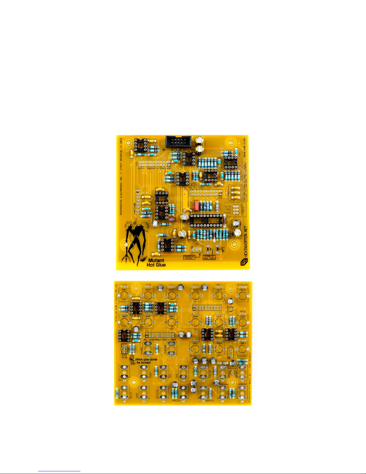
We’re going to be assembling both of the PC s at the same time, so get your tools and parts
ready and let’s go!

04.24.2015 Mutant Hot Glue DIY assembly manual v1.05 PG4
HEXINVER ER ÉLEC RONIQUE, 2015
STEP_00: Resistors Diodes

04.24.2015 Mutant Hot Glue DIY assembly manual v1.05 PG5
HEXINVER ER ÉLEC RONIQUE, 2015
•First, install the diodes. The band on the diode matches the band on the PCB silkscreen.
•Diodes are polarity sensitive. It is critical that you install them the right way or the circuit will not work
properly!
•It’s a good idea to set aside your resistor lead clippings for later when we install the test points
•Next, install the resistors. he resistor colour codes for 1% metal film (as supplied in the kits) are as follows…
51R
470R
1k91
4k99
5k1
10k
12k4
24k
33k
57k6
100k
169k
200k
300k
383k
576k
2M

04.24.2015 Mutant Hot Glue DIY assembly manual v1.05 PG6
HEXINVER ER ÉLEC RONIQUE, 2015
STEP_01: IC Sockets
•Install the IC sockets, being careful to orient them correctly. I find it easiest to put a book or something else
with a flat surface on them once they’re installed, then flip the PCB and book over for soldering. his keeps the
IC sockets nice and flat while you solder them in.
04.24.2015 Mutant Hot Glue DIY assembly manual v1.05 PG7
HEXINVER ER ÉLEC RONIQUE, 2015
STEP_02: Power Header, Capacitors Purple LED
•First, install one of the purple LEDs into its place on the MAIN PCB. The longer leg is positive (+) and must
align to the ‘+’ marking on the PCB
•Up next are the ceramic disc and film capacitors. hese are the yellow and blue blobs, and the red box. hey
can be installed in any direction
•he power connector should be installed next, making sure that it is installed in the right orientation (as
shown)
•he electrolytics can be installed now. The negative (-) strip on the capacitors must be aligned ith the
shaded (black) semicircle area on the PCB silkscreen. Just like the LED, the positive (+) leg is the longest.

04.24.2015 Mutant Hot Glue DIY assembly manual v1.05 PG8
HEXINVER ER ÉLEC RONIQUE, 2015
STEP_03: Pin Headers
•Begin by using pliers to snap the 2x40 pin headers into (2x) 2x10 sections and (1x) 2x3 section, as shown. We
included an extra 2x40 header in case you have an accident, or some snapped during shipment.
•Install the headers in the PCBs, making sure to install the female headers on the CONTROL PC (not the MAIN
PCB). his is because the longer profile of the female headers will interfere with component pins on the MAIN
PCB.
•ake your time checking alignment before and during soldering. You want to make sure that the
Take your time checking alignment before and during soldering of the pin headers. You want
to make sure that the PCBs line up nicely so that the standoffs+screws that hold the PCB
sandwich together are aligned properly. It might be a good idea to scre the PCBs together
hile you solder the pin headers, if you ant to guarantee they are aligned ell!
CONTROL PC
MAIN PC
The 2x3 header is saved for the
compressor speed jumper on the
MAIN PC
04.24.2015 Mutant Hot Glue DIY assembly manual v1.05 PG9
HEXINVER ER ÉLEC RONIQUE, 2015
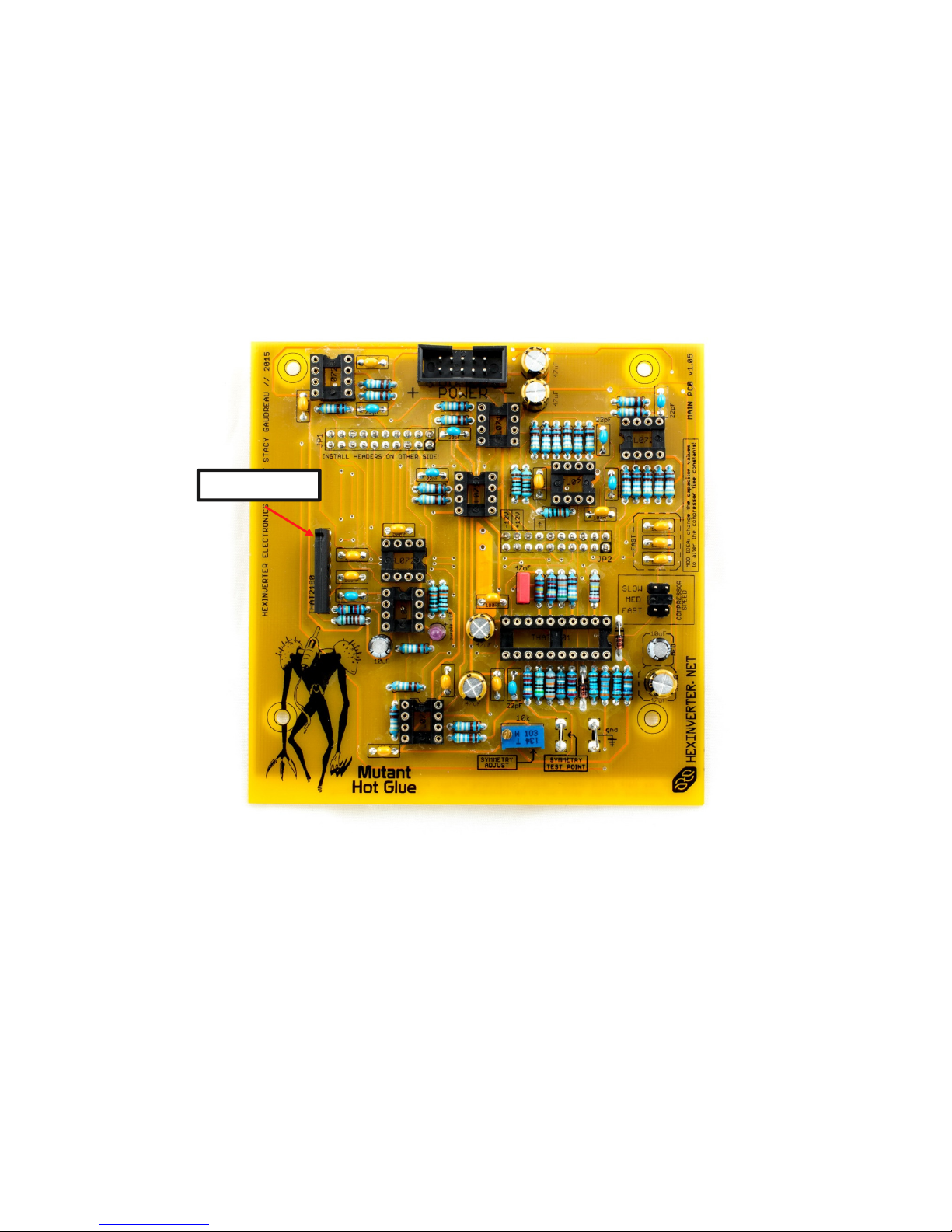
STEP_04: THAT2180, Test Points Jumper
•After installing the jumper on the 2x3 pin header we cut up in the last step, you can solder it in for the
COMPRESSOR SPEED jumper.
•Using a couple of left over component lead clippings, bend them into a ‘U’ shape which fit in the gnd and
SYMMETRY TEST POINT locations, at the bottom right of the MAIN PCB.
•Solder in the 10k trim potentiometer for the SYMME RY ADJUS calibration point
•Finally, solder in the HA 2180 VCA chip. Be careful not to overheat it, and make sure the notch is aligned
here indicated!
NOTCH IS HERE

04.24.2015 Mutant Hot Glue DIY assembly manual v1.05 PG10
HEXINVER ER ÉLEC RONIQUE, 2015
STEP_05: Take a break!
•It is almost time to assemble the control surface (yay)!
•But, first: look over the two PCBs you just populated and make sure there are no missing or shorted solder
joints. You don’t want to put it all together and then find out you missed a few spots with the iron! If you’re
anything like me, it happens more often than you’d like to admit (I’m not actually a robot…hehe)
•If you are feeling tired or rushed, it might be a good idea to rest up before coming at it again. he control board
is for sure the hardest part of assembly and you don’t want to mess it up! So have a fresh, well-rested mind for
this final section.
STEP_06: Prepare the Potentiometers
he included BI echnologies potentiometers all need their locking clip cut off. Grab a pair of sharp cutting pliers and
clip off the little tab of metal on each pot, as shown. Wear eye protection and try to prevent the clippings from flying all
over, by cupping your hand over the cut as you make it! These little bits go flying off in all directions very fast when
clipping.

04.24.2015 Mutant Hot Glue DIY assembly manual v1.05 PG11
HEXINVER ER ÉLEC RONIQUE, 2015
STEP_07: Place the Parts
•Place the 3.5mm jacks, potentiometers and ON-ON toggle switch into the CON ROL PCB but don’t solder
them in yet!
•We’ll do the panel LEDs and 10k trim pot later…
Install one of the nuts onto the
toggle switch
for now
04.24.2015 Mutant Hot Glue DIY assembly manual v1.05 PG12
HEXINVER ER ÉLEC RONIQUE, 2015
STEP_08: Panel Fitment
Remove the protective covering from the panel and install it on the loose-fitting control board components. Finger
tighten the nuts for a few of the potentiometers. Do not solder anything yet!
Make sure everything is sitting nice and flat on the PCB and especially that the pots are seated flat. Once you are
happy, flip the assembly over and solder one leg of each pot. hen inspect and reheat any pots that aren’t perfectly flat,
pushing them down flat on the PCB with your finger while you reheat the one leg you soldered.
he potentiometers set the height the panel is at. hat is, all of the other components follow
the height of the potentiometers. his means you have to align and solder the potentiometers
first, before the other components are soldered!
Leave out these jack nuts for
this step. I shouldn’t have left
these on
(oops)
!

04.24.2015 Mutant Hot Glue DIY assembly manual v1.05 PG13
HEXINVER ER ÉLEC RONIQUE, 2015
STEP_09: Jacks Toggle Switch
•Gently flip the control board with panel attached over so that the jacks fall down with gravity against the panel.
Sit the assembly gently on your desk and inspect to see that each jack is flush with the back of the panel.
•he jacks will be slightly lifted off of the PCB. ry to ensure that they are flush with the panel.
•Unscrew the nut for the toggle switch slightly, to raise it to the same height as the panel.
•When you are happy with the fit, solder each jack and toggle switch, going back to check that they are nicely
against the panel each time.

04.24.2015 Mutant Hot Glue DIY assembly manual v1.05 PG14
HEXINVER ER ÉLEC RONIQUE, 2015
STEP_0A: LEDs Trim Pot
•Remove the nuts holding the panel to the components you just soldered
•Loosely fit the purple and orange LEDs in their places, making sure to install the longer lead to the positive (+)
indicator on the PCB
•Fit the remaining 10k trim pot in its place on the CON ROL PCB (don’t solder it yet!)

04.24.2015 Mutant Hot Glue DIY assembly manual v1.05 PG15
HEXINVER ER ÉLEC RONIQUE, 2015
STEP_0B: Align Solder
•Once again, fit the panel to the CON ROL PCB using only a few nuts
•Carefully align and solder the LEDs and trim pot so that they fit the panel properly

04.24.2015 Mutant Hot Glue DIY assembly manual v1.05 PG16
HEXINVER ER ÉLEC RONIQUE, 2015
STEP_0C: Install ICs
•It’s time to install the ICs in their sockets!
•Be careful to install them in their correct orientation. If they are reversed when you power on the module, the
chips may be destroyed.

04.24.2015 Mutant Hot Glue DIY assembly manual v1.05 PG17
HEXINVER ER ÉLEC RONIQUE, 2015
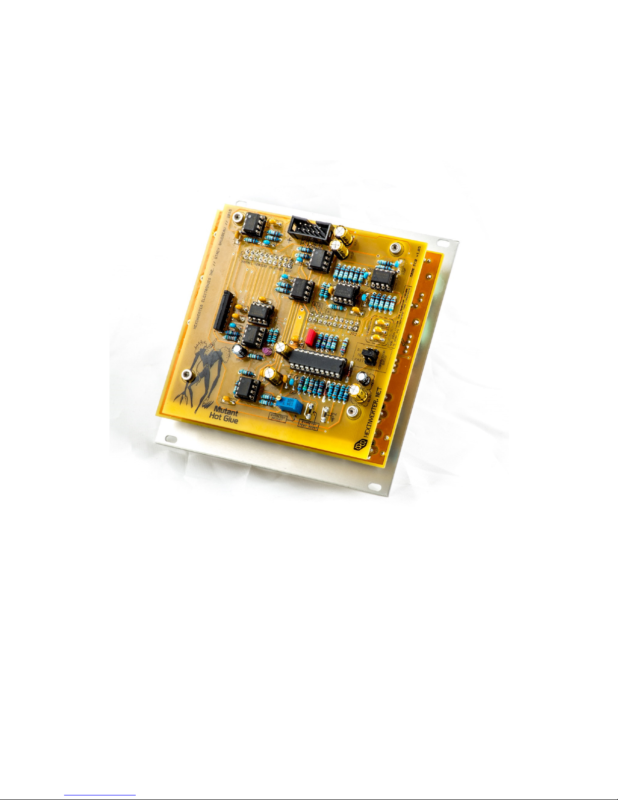
STEP_0D: Assemble the PCB Sandwich
•It’s probably a good idea to give each PCB a final inspection for obvious errors before moving on!
•Using the (8x) M3 screws and (4x) black nylon standoffs, it’s time to put the PCB sandwich together.
•It is recommended to first mount the standoffs tightly onto the CON ROL PCB, and then you can place the
MAIN PCB on top of that and screw it in a little more gently. This ill make it easier should you have to
unscre the MAIN PCB later – it should avoid accidentally loosening the CONTROL PCB’s scre s from the
standoffs at the same time as the MAIN PCB’s scre s.
04.24.2015 Mutant Hot Glue DIY assembly manual v1.05 PG18
HEXINVER ER ÉLEC RONIQUE, 2015
STEP_0E: Looking good!
•Almost done! Sit back and enjoy your work for a second.
•Apply power to your module to make sure nothing gets hot or lights on fire. Does everything work okay?
•If you don’t care about having a perfectly distortion-less compressor, go ahead and skip the next step:
STEP_0F: Compressor Calibration.
04.24.2015 Mutant Hot Glue DIY assembly manual v1.05 PG19
HEXINVER ER ÉLEC RONIQUE, 2015
STEP_0F: Compressor Calibration
•he HA 4130 Dynamics Engine IC, which is the heart of the analog compression circuit, benefits from having
its symmetry bias trimmed for least distortion. You can use the module just fine without it, but the audio
passed through the compressor will have its symmetry distorted somewhat.
•If you do not own a function generator and oscilloscope, you can use a sine wave oscillator and something like
the Jones O’ ool module
•If you use a sine wave oscillator: try to use the most symmetrically accurate one you have – digital is probably
best for symmetry. We don’t care about vertical resolution/bits of the waveform here, so there is no benefit to
analog – it’s the symmetry you want to look out for during this test.
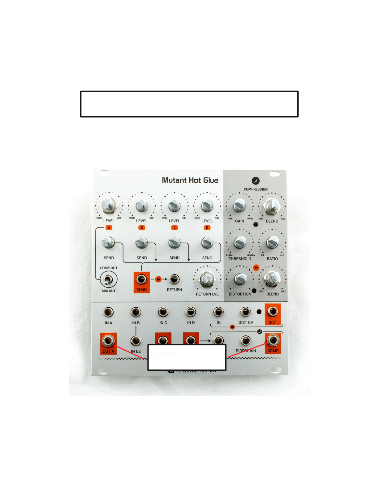
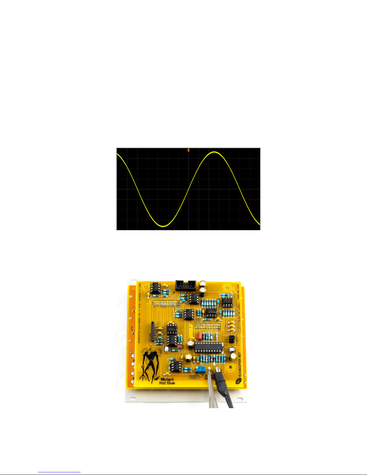
STEP 0: Begin by generating a sine wave, as shown below. Insert this sine wave into the Compressor IN jack.
Use a sine ave around 8Vpp @ 1kHz – exact numbers are not important, but, do make sure it is centered symmetrically about
0V!
STEP 1: If you are using an oscilloscope, clip your probe to the gnd and SYMMETRY TEST POINT clips on the back
of the module which you installed earlier. If you are using an O’ ool, patch into the COMP output.
04.24.2015 Mutant Hot Glue DIY assembly manual v1.05 PG20
HEXINVER ER ÉLEC RONIQUE, 2015
STEP 2: Deactivate the compressor’s gain reduction, with the following settings…
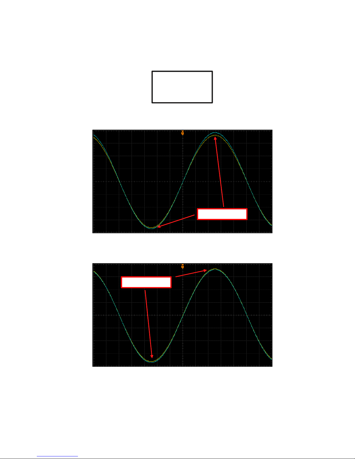
STEP 3: While viewing and comparing the COMP output signal to the input signal, adjust the SYMMETRY ADJUST
control for best vertical symmetry. See the images below for how to do this…
The upper and lo er peaks of the output aveform (blue) are not symmetrical. You can tell
by inspecting the vertical distance bet een the yello and blue aveforms.
At first glance, this might seem okay – but pay close attention! – the output aveform (blue) is above and below the input
aveform! This is not correct, as e ill see in the follo ing correct example.
GAIN = 0dB
BLEND = WE (100%)
HRESHOLD = +26dBu
RA IO = MAXIMUM
POOR SYMMETRY
POOR SYMMETRY
Table of contents


