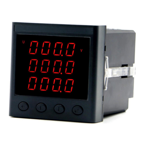
Heyuan Intelligence DZ81-DZS300 User manual

DZ81-DZS300 Energy Meter
User Manual
(V2.0.4)
Heyuan Intelligence Technology Co., Ltd

IMPORTANT DECLARATIONS
Copyright © 2018 Heyuan Intelligence Technology Co., Ltd All Rights Reserved
This manual may not be reproduced, copied, transmitted or transcribed in whole or in part by any means
without the expressed written permission of Heyuan. Any shall be investigated for legal responsibility in
violation of copyright or other intellectual property rights of the Company. We check the user manual’s
contents regularly and will make necessary amendments in next version. Welcome to give advice for
some unexpected errors. The rights of upgrading without notice are reserved.
Please read this manual carefully before the product is operated. And once you start operating the meter,
you’ll be considered to have read this manual and accept all our terms. Heyuan shall not be responsible
or liable for any damages or injuries caused by improper meter installation and/or operation.
Attention: the following symbols in this manual refer to meanings as follows
Electric Shock Symbol: Carries information about procedures which must be followed to
reduce the risk of electric shock and danger to personal health
Safety Alert Symbol: Carries information about circumstances which if not considered may
result in injury or death
The meter must be installed and operated by one who has experience with high-voltage devices or has
qualifications. Please connect the meter to correct voltage before operating the meter. Please install and
use the meter according to the user manual. Heyuan shall not be responsible or liable for any damages
or injuries caused without following the instructions in the user manual.

Contents
Chapter 1 Meter Overview ……………………………………………………………………………......1
Chapter 2 Specifications ………………………………………………………………………………….1
Chapter 3 Dimensions & Installation …….…………………………………………………….…….2
Chapter 4 Terminals ………………………………………………………………………...……….…….2
Chapter 5 Typical Wiring ………………………………………………………………………………….3
Chapter 6 Parameters Display Interfaces ……………………………………………………….…..4
Chapter 7 Parameters Setting Interface ……………………………………….…….……..…………..7
Chapter 8 Basically Measured Parameters Zone (Modbus Protocol) ………………...................10
Chapter 9 Basic Set Parameters Zone (Modbus Protocol) ……………………….…………….….11
Chapter 10 Measurement Parameters (Modbus Protocol) ………………….……………..….…...12
Chapter 11 After-sales Service …………………………………………………………………...…….14
Chapter 12 Contact Us ………………………………………………………………....………..……....14

1
Chapter 1 Meter Overview
DZS300 is an advanced, smart DIN rail energy meter. It is widely used in energy distribution sites,
energy management systems and intelligent on-line monitoring systems of different industries. It can
measure electric parameters i.e. three-phase voltage, three-line voltage, three-phase current,
harmonics (2nd-31st), active power, reactive power, apparent power, power factor, frequency, active
energy, reactive energy, multi-tariff energy etc. with high accuracy.
Chapter 2 Specifications
2.1 Input Voltage
Reference Voltage: 3×220V/380V Voltage Range: 0.6Un~1.2Un
2.2 Input Current
Measuring Range: 1‰In~4In Current Range: 20(80)A
2.3 Energy
Accuracy Class: Class 0.5S Resolution: 0.01kWh
2.4 Frequency Measurement
Frequency Measuring Range: 45~65Hz
2.5 Measuring Accuracy
Voltage/Current: 0.2% Power Factor: 1%
Frequency: ±0.01Hz
2.6 Communication
RS485/Modbus-RTU Communication Protocol Baud Rate: 1200~9600bps (settable)
Remark: DZ81-DZS300 adopts RS485 interfaces and Modbus RTU communication
protocol to communicate. The terminals are 485A and 485B. The RS485 transmission
medium is shielded twisted pair.
2.7 Power Supply
Power Supply: AC85~265V(45~55HZ)/ DC85~300V Power Consumption: <3VA
2.8 Pulse Output Interface
Terminals PE+ and PE- are pulse output interface. The import active energy output is
settable.
2.9 Pulses Per Second(PPS) Output Interface
Terminals SEC+ and SEC- are PPS output interface. When the real-time clock update per

2
second, the interface will output a high-level pulse of 500ms(+/-2ms).
2.10 Working Condition
Operating Temperature: -20℃~+65℃ Storage Temperature: -40℃~+85℃
Relative Humidity: 20%~90%(non-condensing)
Chapter 3 Dimensions & Installation
3.1 Overall Dimension and Cut-out Size (unit: mm)
Top View (Unit: MM) Side View (Unit: MM)
Model No.
Dimension(mm)
DZ81-DZS300
L.
W.
H.
126
89
74
3.2 Installation Method
Installation Environment: DZS300 should be installed in a dry and dust free environment. Avoid
exposing meter to excessive heat, radiation and high electrical noise sources.
Install Method: DIN rail Mounting.
Chapter 4 Terminals
1
9
10
2
11
12
3
13
14
4
In1
Ic1
Ib1
Ia1
In2
Ic2
Ib2
Ia2
In3
Ic3
Ua
Ia
Ia*
Ub
Ib
Ib*
Uc
Ic
Ic*
Un
Upper Row of Terminals
Lower Row of Terminals
20
19
18
17
16
15
485A
485B
PE+
PE-
SEC+
SEC-

3
Chapter 5 Typical Wiring
5.1 Wiring Approach 1
5.2 Wiring Approach 2

4
5.3 Interface of Energy Pulse Output 5.4 RS485 Interface 5.5 PPS Output Interface
PE+ PE-
18 17
20 19
485B
485A
SEC+ SEC-
16 15
Chapter 6 Parameters Display Interfaces
6.1 Interfaces of Voltage, Current and Date
Press button " " to cyclically display interfaces of voltage, current and date.
6.2 Interface of Energy
Press the button " " to cyclically display interfaces of total active energy, import active
energy, export active energy, total reactive energy, import reactive energy and export
reactive energy.
6.3 Interface of Power
Press button " " to cyclically display interfaces of active power, reactive power, apparent
power, power factor, frequency, total active power, total reactive power, total apparent
power, total power factor, voltage unbalance, current unbalance etc.

5
%
%
6.4 Interface of Harmonics
Press the buttons " " and "" simultaneously to enter harmonics display interfaces. Press
buttons " " to cyclically display interfaces of total voltage harmonic content, total current
harmonic content, total voltage odd harmonic content, total voltage even harmonic content,
total current odd harmonic content, total current even harmonic content, voltage 2nd
harmonic content, current 2nd harmonic content. On interfaces of voltage 2nd harmonic
content and total voltage harmonic content, press button " " to cyclically display interfaces
of voltage 2nd~31st harmonic content. On interface of current 2nd harmonic content, press
button " " to cyclically display interfaces of current 2nd~31st harmonic content.

6
6.5 Interface of Historical Multi-tariff
Press the buttons " " and " " simultaneously to enter multi-tariff display interface. Press the
button " " to cyclically display energy of N months (N referring to 0~11, 0 signifying present month).
Press button " " to display energy in sharp, peak, normal, valley from last N months. Press button
" " to display total active energy, import active energy, export active energy, total reactive energy,
import reactive energy, export reactive energy.
kWh
1
Imp
1
2
3
4

7
Chapter 7 Parameter Setting Interface
E
P
U/I
DZS300
On measured value display interface, press buttons
the " " and " " at the same time, it will enter total parameters setting mode. Under
setting mode, the button " " will be used for digital shift. It can edit 1 digit shift left each
time, and the digit will flash. The button " " is used to plus 1, i.e., the flashing digit will
plus 1 when pressing " " each time. If the flashing digit is 9, then press " " and the digit
will become 0. The button " " is used to confirm setting and enter the next setting interface.
On any setting interface, press " " and " " simultaneous and it will quit setting mode to
switch to measured value display interface.

8
7.1 Password Setting Interface
Press buttons " " and " " at the same time, it will enter total
parameters setting mode. Enter password setting interface, the default password is 0001.
If the password is not correct, press button " "(U/I). Then the upper right corner will show
a warning sign. If the password is correct, press " " to enter address setting interface.
7.2 Address Setting Interface
Enter address setting interface. The present meter address is 001.
Setting range is 1-247. The address setting should comply with the requirements of register
table. Press button " " to confirm and enter setting interface of communication
parameters.
7.3 Communication Parameter Setting Interface
Enter communication parameter setting interface. The present
parameter of RS485 communication is "8n1". Press the button " " to set the parameters
as "8n1", "8o1", "8e1". Press button " " to confirm and enter baud rate setting interface.
7.4 Baud Rate Setting Interface
Enter baud rate setting interface. The present baud rate of RS485 is
9600. Press the button " " to set the parameters as 1200, 2400, 4800 or 9600. After
completing setting, press button " " to confirm and enter wiring mode setting interface.
7.5 Wiring Mode Setting Interface
On wiring mode setting interface, the present wiring mode is 3-phase
4-wire. It can be set as “2LL” 3-phase 4-wire and “3Ln” 3-phase 4-wire by pressing the
button " ". After setting it, press “Enter” to enter voltage ratio setting interface.

9
7.6 Voltage Ratio Setting Interface
Enter voltage ratio setting interface, the present voltage ratio is 0001.
Voltage ratio setting should comply with the requirements of register table. Press the
buttons " " and " " to set the range of voltage ratio among 1-9999. After completing
setting, press button " " to confirm and enter current ratio setting interface.
7.7 Current Ratio Setting Interface
Enter current ratio setting interface. The present current ratio is
0001. Press the buttons " " and “ ” to set the range of current ratio among 1-9999. After
setting, press button " " to confirm and enter pulse output type setting interface.
7.8 Pulse Output Type Setting Interface
Enter setting interface of pulse output type. The present interface
displays the pulse type as full-wave active pulse. Among the values, 0 signifies full-wave
active power pulse, 1 signifies full-wave reactive power pulse, 2 signifies full-wave apparent
power pulse, 3 signifies fundamental wave active pulse, 4 signifies fundamental wave
reactive power pulse, 5 signifies fundamental wave apparent power pulse. Press the button
" " to select energy pulse output type. After completing setting, press button " " to
confirm and enter setting interface of pulse per second(PPS).
7.9 PPS Output Type Setting Interface
Enter setting interface of pulse per second(PPS). The present
interface displays the PPS output from the PPS port. Press the button " " and the values
can be set as 0 signifying fundamental wave active energy output, 1 signifying PPS output.
After completing setting, press button " " to confirm and enter setting interface of
backlight time interface.
7.10 Backlight Setting Interface

10
Enter setting interface of backlight time. The present interface displays
the backlight time is 10s (100ms as a unit). Press the button " " and " " to set the
backlight time among 10~600(i.e. 1s to 60s). After completing setting, press button " " to
confirm and return to setting interface of address.
7.11 Password Setting Interface
Press buttons " " and " " at the same time, it will enter total
parameters setting mode. Enter password setting interface, when setting password as 1111,
press " " to enter setting interface of energy ratio.
7.12 Energy Ratio Setting Interface
Enter setting interface of energy ratio switch setting interface. Press
button " " to set the energy ratio, among which 0 signifies “ON” while 1 signifies “OFF”.
After completing setting, press button " " to confirm and enter setting interface of decimal
places.
7.13 Decimal Place Setting Interface
Enter setting interface of decimal place setting interface. The
present interface displays the 2 decimal places. Press button " " to set the decimal places
from 1~3. When setting decimal place as 0, 4 or values over 4, there will be an exclamation
mark at the left corner, which means it is unsettable. After completing setting, press button
" " to confirm and return to password setting interface.
Chapter 8 Basically Measured Parameters Zone (Modbus Protocol)
Address
Address
Parameter Name
Default Value
Value Range
DEC
HEX
4096
1000
phase A voltage
Magnifying 100 times
0~65535
4097
1001
phase B voltage
Magnifying 100 times
0~65535
4098
1002
phase C voltage
Magnifying 100 times
0~65535

11
4099
1003
reserved
0xffff
0~65535
4100
1004
reserved
0xffff
0~65535
4101
1005
line voltage(A-B)
Magnifying 100 times
0~65535
4102
1006
line voltage(B-C)
Magnifying 100 times
0~65535
4103
1007
line voltage(C-A)
Magnifying 100 times
0~65535
4104
1008
reserved
0xffff
0~65535
4105
1009
phase/line current of phase A
Magnifying 1000 times
0~65535
4106
100A
0~65535
4107
100B
phase/line current of phase B
Magnifying 1000 times
0~65535
4108
100C
0~65535
4109
100D
phase/line current of phase C
Magnifying 1000 times
0~65535
4110
100E
0~65535
4111
100F
reserved
0xffff
0xffff
4112
1010
reserved
0xffff
0xffff
4113
1011
phase A active power
Magnifying 1000 times
-32768~32767
4114
1012
phase B active power
Magnifying 1000 times
-32768~32767
4115
1013
phase C active power
Magnifying 1000 times
-32768~32767
4116
1014
total active power
Magnifying 1000 times
-32768~32767
4117
1015
phase A reactive power
Magnifying 1000 times
-32768~32767
4118
1016
phase B reactive power
Magnifying 1000 times
-32768~32767
4119
1017
phase C reactive power
Magnifying 1000 times
-32768~32767
4120
1018
total reactive power
Magnifying 1000 times
-32768~32767
4121
1019
phase A apparent power
Magnifying 1000 times
-32768~32767
4122
101A
phase B apparent power
Magnifying 1000 times
-32768~32767
4123
101B
phase C apparent power
Magnifying 1000 times
-32768~32767
4124
101C
total apparent power
Magnifying 1000 times
-32768~32767
4125
101D
phase A power factor
Magnifying 100 times
-100~100
4126
101E
phase B power factor
Magnifying 100 times
-100~100
4127
101F
phase C power factor
Magnifying 100 times
-100~100
4128
1020
total power factor
Magnifying 100 times
-100~100
4129
1021
frequency
Magnifying 100 times
0~65535
4130
1022
voltage unbalance
Magnifying 1000 times
4131
1023
current unbalance
Magnifying 1000 times
Chapter 9 Basic Set Parameters Zone (Modbus Protocol)
Address
Address
Parameter Name
Default
Value
Value Range
DEC
HEX
8192
2000
Password protection (basic
parameter protection)
0001
0~9999
8193
2001
Communication address
1
1~247

12
Address
Address
Parameter Name
Default
Value
Value Range
DEC
HEX
8194
2002
RS485 serial port parameter
0
High :0:(N,8,1) ,1:(o,8,1) ,
2:(e,8,1)
8195
2003
RS485 serial port parameter
3
0:1200,1:2400, 2:4800, 3:9600,
8196
2004
Voltage connection mode
0
0:3LN,1:2LL
8197
2005
PT
1
1∼9999 (Remark 1)
8198
2006
CT
1
1~9999 (Remark 1)
8199
2007
DO1 pulse output energy
selection
0
0: full-wave active power pulse
1: full-wave reactive power
pulse
2: full-wave apparent power
pulse
3: fundamental wave active
power pulse
4: fundamental wave reactive
power pulse
5: fundamental wave apparent
power pulse
8200
2008
DO2 pulse output port
0
0: fundamental wave active
energy output
1:PPS Output
8201
2009
Backlight time
100
10-600 (Remark 2)
8202
200A
Monthly energy transferred
time
1
1-30
Remark 1: The product of voltage and current should be less than 300,000.
Remark 2: The unit of time is 100ms
Chapter 10 Measurement Parameters (Modbus Protocol)
Real-time Clock Zone(( Function Code 0x10 Write; Function Code 03/04 Read)
Address
Address
Type
Parameter Name
Value range
DEC
HEX
12800
3200
Year
2000
2000-2099
12801
3201
Month
1
1-12
12802
3202
Day
1
1-31
12803
3203
Hour
0
0-23
12804
3204
Minute
0
0-59

13
12805
3205
Second
0
0-59
12806
3206
Millisecond
0
0-999
Remark:
1. Write register to set time, read register to read time of the meter. In order to prevent the
occurrence of February 31st, the "Time" must be set by the command 10H, otherwise invalid. The
clock chip automatically falls milliseconds to zero. So milliseconds can only be readable.
Real-time Energy Consumption—Four-quadrant LCD Display
(Function Code 03/04 Read)
Address
Address
Type
Parameter Name
Value range
DEC
HEX
16384
4000
Total Real-
time energy
consumption
Total active energy
0~9999999.99
16385
4001
16386
4002
Import active energy
0~9999999.99
16387
4003
16388
4004
Export active energy
0~9999999.99
16389
4005
16390
4006
Total reactive energy
0~9999999.99
16391
4007
16392
4008
Import reactive energy
0~9999999.99
16393
4009
16394
400A
Export reactive energy
0~9999999.99
16395
400B
The following parameters are not listed. If necessary, please contact Heyuan to get them.
Address
Parameter Name
DEC
HEX
4352-4560
1100-11DO
Harmonic Parameters Zone
8448-8477
2100-211D
Multi-tariff Time Setting Zone
16640-19585
4100-4C81
Multi-tariff Historical Energy Zone

14
Chapter 11 After-sales Service
Product Warranty
1. The product warranty period is one year.
2. The company is responsible for free maintenance or exchange within three -year
warranty period.
3. The cost of the components and freight shall be charged for improper meter installation
and/or operation.
4. Over the warranty period, part of the maintenance cost according to actual situation
will be charged.
Service Guarantee
1. Product technical consulting and quality complaints will be replied within 12 hours.
2. Solutions for quality complaints will be provided within 24 hours.
3. Except statutory holidays and force majeure.
Chapter 12 Contact Us
Headquarter Add.: 7F No.1 Aosheng Building, 1166 Xinluo Street, High-tech Development Zone,
Jinan, P.R. China 250101
Factory Add.: 2F Innovation Factory, Feiyue Road, High-tech Development Zone, Jinan,
P.R. China 250101
Tel: +86 68621770-863
Code: 250101
E-mail: info@hyznworld.com
Table of contents
Other Heyuan Intelligence Measuring Instrument manuals

Heyuan Intelligence
Heyuan Intelligence DZ81-MSU7C User manual

Heyuan Intelligence
Heyuan Intelligence DZ81-MS3UI7C User manual

Heyuan Intelligence
Heyuan Intelligence DZS100-4P User manual

Heyuan Intelligence
Heyuan Intelligence DZ81-METZ5C User manual
Heyuan Intelligence
Heyuan Intelligence DZ81-MS3UI7E3 User manual
Heyuan Intelligence
Heyuan Intelligence DZ81-DZS310 User manual

Heyuan Intelligence
Heyuan Intelligence DZ81-MA3UI5C User manual