Heyuan Intelligence DZ81-METZ5C User manual

DZ81-METZ5C
Intelligent Power Meter
User Manual
(V1.0)
Heyuan Intelligence Technology Co., Ltd

IMPORTANT DECLARATIONS
Copyright © 2018 Heyuan Intelligence Technology Co., Ltd All Rights Reserved
This manual may not be reproduced, copied, transmitted or transcribed in whole or in part by any
means without the expressed written permission of Heyuan. Any shall be investigated for legal
responsibility in violation of copyright or other intellectual property rights of the Company. We check
the user manual’s contents regularly and will make necessary amendments in next version. Welcome
to give advice for some unexpected errors. The rights of upgrading without notice are reserved.
Please read this manual carefully before the product is operated. And once you start operating the
meter, you’ll be considered to have read this manual and accept all our terms. Heyuan shall not be
responsible or liable for any damages or injuries caused by improper meter installation and/or
operation.
Attention: the following symbols in this manual refer to meanings as follows
Electric Shock Symbol: Carries information about procedures which must be followed
to reduce the risk of electric shock and danger to personal health
Safety Alert Symbol: Carries information about circumstances which if not considered
may result in injury or death
The meter must be installed and operated by one who has experience with high-voltage devices or
has qualifications. Please connect the meter to correct voltage before operating the meter. Please
install and use the meter according to the user manual. Heyuan shall not be responsible or liable for
any damages or injuries caused without following the instructions in the user manual.

Contents
Chapter 1 Meter Overview …………………………………………………………………………….......1
1.1 Overview…………………………………………………....................................................1
1.2 Main Functions…………………………………………………...........................................1
Chapter 2 Specifications ………………………………………………………………………………….2
2.1 Input Voltage ………………………………………………….............................................2
2.2 Input Current …………………………………………….................................. .................2
2.3 Frequency Measurement …………………………………………………..........................2
2.4 Measuring Accuracy ……………………………………....................................................2
2. 5 Communication……………………………………...........................................................2
2.6 Power Supply…………………………………….............................................. ................2
2. 7 Working Condition…………………………………….......................................................2
2.8 Pulse Constant……………………………………............................................................2
Chapter 3 Dimension and Installation ……………………………………………………………….…2
3.1 Dimension …………………………….……………...........................................................2
3.2 Installation Method ……………………………………………….................. .....................3
Chapter 4 Typical Wiring ………………………………………………………………………….………3
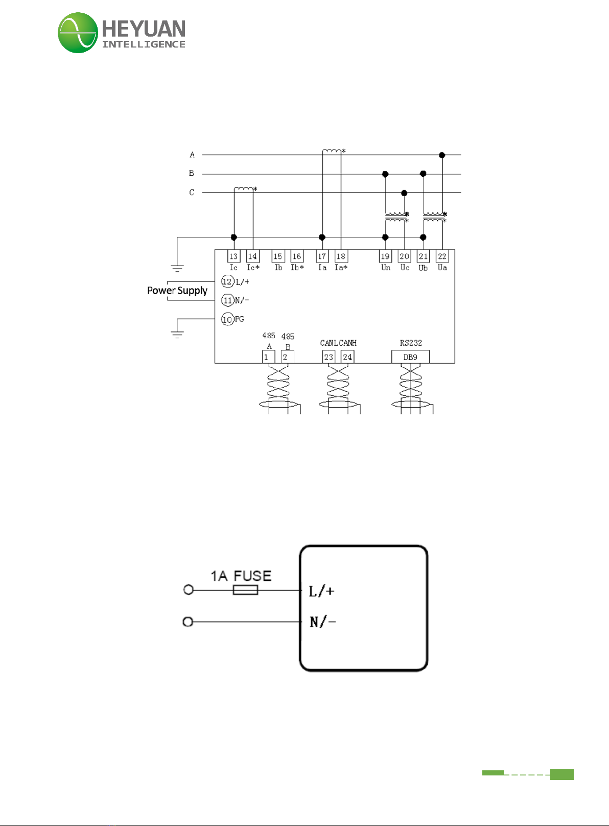
4.1 3-phase 4-wire Wiring Mode (3LN, 3CT)........................................................................3
4.2 3-Phase 3-Line Open Delta Mode (2LL, 2CT) ...............................................................4
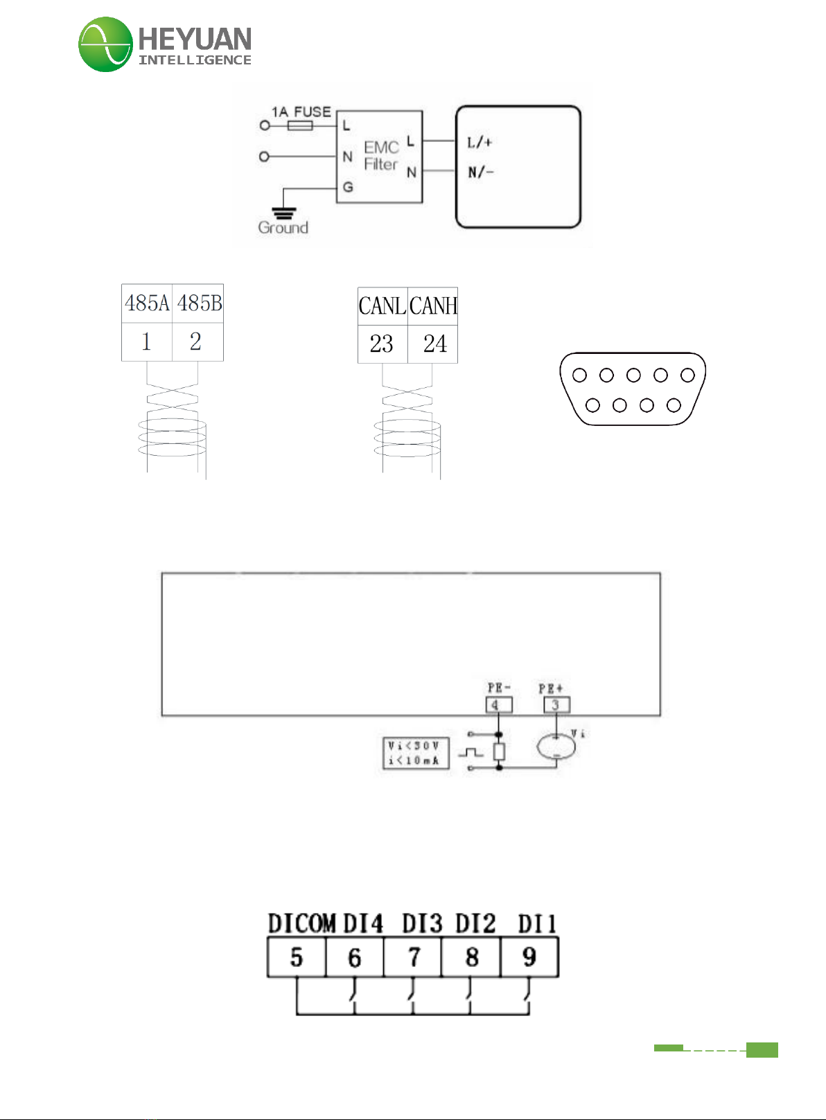
4.3 Power Supply.................................................................................................................4
4.4 Communication Interface...............................................................................................5
4.5 Energy Pulse Output .....................................................................................................5
4.6 Digital Input ....................................................................................................................5
4.7 Other Wiring Mode ........................................................................................................6
Chapter 5 Meter Display and Operation ........................................................................................6
5.1 Phase Voltage, Line Voltage and Current Display Interfaces ........................................6
5.2 Energy Display Interfaces ..............................................................................................6
5.3 Power Display Interfaces ...............................................................................................7
5.4 THD (Total Harmonic Distortion) Display Interfaces .......................................................7
5.5 Multi-tariff Display Interface ....................................................... ...................................8
Chapter 6 Parameter Setting Interface ...........................................................................................9
6.1 System Parameter Setting .............................................................................................9
6.2 Password Inquiry Interface ..........................................................................................10
6.3 Back-light Time Setting Interface.............. ............... ...................................................10
6.4 Meter ID Setting ...........................................................................................................10
6.5 Communication Parameter Setting Interface ...............................................................11
6.6 Voltage Wiring Mode Setting Interface ........................................................................11
6.7 Current Wiring Mode Setting Interface .........................................................................11
6.8 PT Ratio Setting Interface .......................................................................................... 12
6.9 CT Ratio Setting Interface ...........................................................................................12
Chapter 7 After-sales Service .......................................................................................................13
Chapter 8 Contact Us ....................................................................................................................13

1
Chapter 1 Meter Overview
1.1 Overview
DZ81-METZ5C is an advanced, smart multifunctional energy meter. It is widely used in power
distribution sites, energy management systems and intelligent monitoring systems of different
industries. Measuring all parameters: three phase/line voltage, three phase current, zero-sequence
voltage, zero-sequence current, voltage unbalance, current unbalance, active power, reactive power,
power factor, frequency, load property, analysis of harmonic(2~31times), active/reactive energy,
multi-tariff, four-quadrant electric energy, SOE event records etc. It has 4-channel digital input (DI),
4-channel relay output (DO), and 1-channel energy pulse output, and supports standard Modbus
RTU communication protocol.
Display: LCD display
1.2 Main Functions
·Telemetery:
Measuring all parameters of power: three-phase current, three-phase voltage, zero sequence
voltage, zero sequence current, active power, reactive power, apparent power, frequency, power
factor, load property etc.
·Teleindication:
4 digital inputs, supporting SOE (Sequence of Event) and COS (Change of State)
·Telecommand:
4 digital outputs; optional level output mode or pulse output mode; and adjustable hold time output.
·Off-limit Alarm:
2 levels of alarm when there is over current/ voltage, under voltage or voltage loss in loop; respond
in less than 20ms; settable alarm value and alarm time
·Energy Metering:
Bidirectional active and reactive energy metering; four-quadrant reactive energy metering; 4 tariffs’
energy metering in 10 periods of time
·Fault Wave-recording:
Fault wave-recording for the telemetery value in every channel; Launch condition of the fault
waveform record: overload and trip fault
·Multi Communication Interfaces:
RS485, RS232, CAN interfaces
·Parameter Adjusting:
Parameters of device can be remotely adjusted, such as: telecommand hold time output, thresholds
of telemetery trend changes, telemetery alarm value and alarm time; input and starting conditions of
the fault wave-recording. All running data, logging and system setting can be visited and adjusted
both locally and remotely.
·Data Logging:

2
Logging for teleindication displacement, telemetery off-limit, fault diagnosis, communication failure.
After power off, transmission in each channel can be continued and logging for SOE, telemetry curve
and wave-recording data can be saved. The data will be uploaded automatically after power on
·Self-diagnostic Function:
After power on, self-diagnosis about communication, adjusting value, clock, memory, system data is
available
·Real-time Clock:
With built-in clock chip, time checking through software from dispatch end is available.
Chapter 2 Specifications
2.1 Input Voltage
Rated Voltage: 3×220V/380V AC Voltage Range: 0~1.2Un
2. 2 Input Current
Rated Current: 1A/5A
2.3 Frequency Measurement
Frequency Measuring Range: 45~65Hz
2. 4 Measuring Accuracy
Voltage/Current: 0.2% Energy Accuracy: Class 0.5S Power Factor: 0.1%
Frequency: ±0.01Hz
2. 5 Communication
RS485/Modbus-RTU Communication Protocol Baud Rate: 2400~19200bps (programmable)
2.6 Power Supply
Power Supply: AC85~265V
Power-line Connection Terminals: L/+ and N/-
2. 7 Working Condition
Operating Temperature: -20℃~+65℃ Storage Temperature: -40℃~+85℃
Relative Humidity: 20%~90%(non-condensing)
2.8 Pulse Constant
Pulse constant: 9600imp/kWh
Chapter 3 Dimension and Installation
3.1 Dimension (unit: mm)

3
91
91
Cut-out Size (unit: mm) Side View (unit: mm)
3.2 Installation Method
This series of products should be installed in a dry and dust free environment, and avoid exposing
to excessive heat, radiation and high electrical noise source. The meters can be installed into a
standard panel cutout of switch cabinet.
Step1. Remove the clips from the meter and insert the meter into the cutout from the front side. Make
sure that the screen is at the front of the panel.
Step2. Install clips on the back side of the meter and secure tightly to ensure the meter is affixed to
the panel.
Chapter 4 Typical Wiring
4.1 3-phase 4-wire Wiring Mode (3LN, 3CT)

4
The star-like 3-Phase 4-Line wiring mode is commonly used in low-voltage electric distribution power
systems. The “UL” (voltage wiring mode) on the parameter setting interface should be set as “3Ln”;
“IL” (current wiring mode) should be set as “3C”.
4.2 3-Phase 3-Line Open Delta Mode (2LL, 2CT)
Open delta wiring mode is often used in high-voltage systems. The “UL” (voltage wiring mode) on
the parameter setting interface should be set as “2LL”; “IL” (current wiring mode) should be set as
“2C”.
4.3 Power Supply
The power supply for this meter is AC85-265V (45-55Hz) or DC85-300V. Terminals for the power
supply are (L/+,N/-). The typical power supply wiring is as follows
If the quality of power is poor or there is an EMI problem, it’s recommended to equip an EMC filter
in the auxiliary power supply loop to increase resistance to interference. The wiring mode is as
follows

5
4.4 Communication Interface
RS485 CAN RS232
4.5 Energy Pulse Output
Energy pulse output (pulse constant is 9600 imp/kWh): Terminal “PE-” and “PE+” are active energy
pulse output.
4.6 Digital Input
The real quantity of digital input is up to the model number of the meter. Its wiring mode is as follows.

6
4.7 Other Wiring Mode
Chapter 5 Meter Display and Operation
There are four buttons on the front panel, labeled button “H”, button “P”, button “E” and button “V/A”
from left to right. It can be used for reading different real-time data and setting parameters though
the four buttons.
5.1 Phase Voltage, Line Voltage and Current Display Interfaces
Press button “V/A”, it will cyclically display the values of phase voltage(U), line voltage (UL) and
current(I) etc.
5.2 Energy Display Interfaces
Press button “E”, it will cyclically display the values of energy parameters.

7
5.3 Power Display Interfaces
Press button “P”, it will cyclically display the values of power parameters.
5.4 THD (Total Harmonic Distortion) Display Interfaces
Press button “H”, it will cyclically display the total harmonic distortion of voltage and current.
Press “H” and “E” simultaneously, the meter will display the 2nd~31st HC (harmonic content). The
harmonic order will plus 1 from 2nd to 31st each time pressing button “P”. And the harmonic order
will minus 1 by one each time pressing button “E”. And press buttons “H” and “E” again, it will switch
back to display interface of voltage & current.

8
5.5 Multi-tariff Display Interface
Press buttons “E” and “V/A” simultaneously, it will enter the interface of historical multi-tariff.
Press button “V/A” to switch the last Nth-month energy (N represents 00~11).
Press button “E” to switch the interfaces of active energy, reactive energy and apparent energy etc.
Press button "H" to switch the interfaces of energy in sharp, peak, shoulder or off-peak period.
Press “E” and “V/A” at the same time, it will exit the interface of historical multi-tariff.
No
Item
Description
1
Active; Reactive; Apparent
(through pressing“E”to
shift)
EP: Active Energy;
EQ: Reactive Energy;
ES: Apparent Energy
2
Reactive Energy in
Quadrants (through pressing
“E”to shift)
Number 1~4 represent the 1st to the 4th quadrant
3
Multi-tariff
(through pressing“H”to
shift)
:Sharp Period :Peak Period
:Shoulder Period :Off-peak Period
4
Energy Type
(through pressing“E”to
shift)
Imp: Import energy
Exp: Export energy
Total: Absolute value and electrical energy
Net: Net energy
5
Historical Energy
(through pressing“V/A”to
shift)
Number 00~11 represent the present month to the
last 11th month

9
Chapter 6 Parameter Setting Interface
6.1 System Parameter Setting
Press buttons “H” and “V/A” simultaneously at any display interface of metering data, it will enter
the system setting interface.
At the setting mode:
The button “H” is used for digital shift. Press button “H” each time to shift one digit, which will flash
at the same time.
The button “P” is used to plus 1. Press button “P” each time and the flashing digit plus 1. If the
flashing digit is 9, press button "P" and the digit will become 0.
The button "E" is used to minus 1. Press button “P” each time and the flashing digit minus 1. If the
flashing digit is 0, press button "E" and the digit will become 9.
The button “V/A” is used to confirm the setting and switch to the next setting interface. Press button
“H” and “V/A” simultaneously at any setting interface, it will exit the setting interface and switch to
the display interface of metering data.
Press buttons “H” and “V/A” simultaneously at any setting interface, it will exit the setting interface
and turn to the metering data display interface.

10
6.2 Password Inquiry Interface
Press “H” and “V/A” simultaneously at any display interface of metering data, it will enter password
setting interface. The default password is 0000. Press button “V/A” to confirm and enter back-light
time setting interface. If the password is not correct, the meter won’t enter next interface and an
alarm icon ( ) will flash in the lower-left corner. If the password is correct, it will enter the next
setting interface.
6.3 Back-light Time Setting Interface
”BL” interface is the page of backlight time setting. At this page, the user can see and set the
backlight time. The value range is 1-999. After the setting is completed, press “V/A” to confirm and
enter the next setting interface.
6.4 Meter ID Setting
At this page the user can see and set the address of meter. The value is 1-247, After the setting is
completed, press “V/A” to confirm and enter the next setting interface.

11
6.5 Communication Parameter Setting Interface
”CM 0” interface is used for setting the RS485 communication parameters.
And ”CM 1” interface is used for setting the RS232 communication parameters.
The default communication parameter setting is 9600-n81.
The baud rate can be set as 19200, 9600, 4800, 2400.
The communication parameter can be set as "8n1", "8o1", "8e1".
Parity: n (no parity), o (odd parity), e (even parity)
Data bits: 8 Stop bit: 1
After the setting, please press "V/A" to confirm and enter the next setting interface.
On communication parameter setting interface, the present baud rate is 9600. The RS485
communication parameter is n81.
6.6 Voltage Wiring Mode Setting Interface
There are 3 options for the voltage wiring modes, i.e. “3Ln” referring to 3-phase 4-wire wiring mode;
“2Ln” referring to 3-phase 4-wire star-like wiring mode, “2LL” referring to 3-phase 3-wire open delta
wiring mode. The setting methods are as follows. Press button “P” or “E” to change and choose the
wiring method. After setting is completed, press button “V/A” to confirm and enter current wiring
mode setting interface.
6.7 Current Wiring Mode Setting Interface

12
There are 3 options for the current wiring modes, i.e. “3C” referring to 3 CTs used for current:
wiring:“2C” referring to 2 CTs used for current wiring to calculate phase B current in three-phase
balanced environment and “1C” referring to 1 CT used for current wiring to meter phase A current
only, which equals to phase B current and phase C current separately in three-phase balanced
environment.
Step 1. Press button “P” or “E” to change and choose the wiring method.
Step 2. After setting is completed, press button “V/A” to confirm and enter PT ratio setting interface.
6.8 PT Ratio Setting Interface
On PT ratio setting interface, the value range is 1~9999.
After setting is completed, press button “V/A” to confirm and enter CT ratio setting interface.
6.9 CT Ratio Setting Interface
On CT ratio setting interface, the value range is 1~9999.

13
After setting is completed, press button “V/A” to confirm and switch back the back-light time setting
interface.
For example, if the PT ratio is 10KV/100V, the PT ratio will be 100, that is to divide 10,000 by 100.
The CT ratio setting is the same as PT ratio setting.
Remark: the product of PT ratio and CT ratio is not more than 300,000.
Chapter 7 After-sales Service
Product Warranty
1. The product warranty period is one year.
2. The company is responsible for free maintenance or exchange within one-year warranty period.
3. The cost of the components and freight shall be charged for improper meter installation and/or
operation.
4. Over the warranty period, part of the maintenance cost according to actual situation will be
charged.
Service Guarantee
1. Product technical consulting and quality complaints will be replied within 12 hours.
2. Solutions for quality complaints will be provided within 24 hours.
3. Except statutory holidays and force majeure.
Chapter 8 Contact Us
Headquarter Add.: 7F No.1 Aosheng Building, 1166 Xinluo Street, High-tech Development Zone,
Jinan, P.R. China 250101
Factory Add.: 2F Innovation Factory, Feiyue Road, High-tech Development Zone, Jinan, P.R. China
250101
Tel: +86 68621770-863
E-mail: info@heyuanintel.com
Website: www.heyuanintel.com
Table of contents
Other Heyuan Intelligence Measuring Instrument manuals

Heyuan Intelligence
Heyuan Intelligence DZ81-MA3UI5C User manual

Heyuan Intelligence
Heyuan Intelligence DZ81-DZS310 User manual

Heyuan Intelligence
Heyuan Intelligence DZS100-4P User manual

Heyuan Intelligence
Heyuan Intelligence DZ81-MS3UI7E3 User manual

Heyuan Intelligence
Heyuan Intelligence DZ81-MSU7C User manual

Heyuan Intelligence
Heyuan Intelligence DZ81-DZS300 User manual

Heyuan Intelligence
Heyuan Intelligence DZ81-MS3UI7C User manual