HF HF-LPT230 Series User manual

HF-LPX30 Series Low Power WiFi Module User Manual
Shanghai High-Flying Electronics Technology Co., Ltd(www.hi-flying.com) - 1 -
HF-LPT230
Low Power WiFi Module User Manual
V 2.0
Overview of Characteristic
Support IEEE802.11b/g/n Wireless Standards
Based on Cortex-M4 SOC, 160MHz CPU, 352KB RAM for 1MB Flash Version, 384KB for
2MB Flash
Support UART Data Communication Interface
Support Work As STA/AP/AP+STA Mode
Support SmartLink V8 Function (Provide APP SDK)
Support SmartAPLink Function
Support WeChat Airkiss 2.0, MiniAPP Config
Support Wireless and Remote Firmware Upgrade Function
Support Software SDK for Develop
Support Different Antenna Option
HF-LPT230:Internal PCB or External IPEX
Small Size:

HF-LPX30 Series Low Power WiFi Module User Manual
Shanghai High-Flying Electronics Technology Co., Ltd(www.hi-flying.com) - 2 -
HF-LPT230:22mm x 13.5mm x 3mm, SMT18 package
FCC/CE/SRRC/RoHS Certificated

HF-LPX30 Series Low Power WiFi Module User Manual
Shanghai High-Flying Electronics Technology Co., Ltd(www.hi-flying.com) - 3 -
TABLE OF CONTENTS
LIST OF FIGURES...................................................................................................................................4
LIST OF TABLES ....................................................................................................................................5
HISTORY..................................................................................................................................................6
1. PRODUCT OVERVIEW ................................................................................................................7
1.1. General Description.................................................................................................................7
1.1.1 Key Application ...................................................................................................................7
1.1.2 Device Paremeters .............................................................................................................8
1.2. Hardware Introduction.............................................................................................................8
1.2.1. HF-LPT230 Pins Definition .................................................................................................9
1.2.2. Electrical Characteristics ..................................................................................................11
1.2.3. HF-LPT230 Mechanical Size ............................................................................................12

HF-LPX30 Series Low Power WiFi Module User Manual
Shanghai High-Flying Electronics Technology Co., Ltd(www.hi-flying.com) - 4 -
LIST OF FIGURES
Figure 1. HF-LPT230-1 and HF-LPT230-0 Appearance .......................................................................9
Figure 2. HF-LPT230 Pins Map.............................................................................................................9
Figure 3. HF-LPT230 Mechanical Dimension......................................................................................12
Figure 4. Suggested Module Placement Region...................................................... 错误!未定义书签。
Figure 5. HF-LPT230 EVK........................................................................................ 错误!未定义书签。
Figure 6. HF-LPT230 Order Information................................................................... 错误!未定义书签。

HF-LPX30 Series Low Power WiFi Module User Manual
Shanghai High-Flying Electronics Technology Co., Ltd(www.hi-flying.com) - 5 -
LIST OF TABLES
Table1. HF-LPT230 Module Technical Specifications ........................................................................8
Table2. HF-LPT230 Pins Definition.....................................................................................................9
Table3. Absolute Maximum Ratings:.................................................................................................11
Table4. Power Supply & Power Consumption: .................................................................................11

HF-LPX30 Series Low Power WiFi Module User Manual
Shanghai High-Flying Electronics Technology Co., Ltd(www.hi-flying.com) - 6 -
HISTORY
Ed. V0.2 07-25-2017 Internal Version.
Ed. V0.2 08-22-2017 Release Version
Ed. V1.1 13-10-2017 Add HF-LPT130A type module
Ed. V1.2 10-11-2017 Add HF-LPB130 type module
Ed. V1.3 03-01-2018 Update HF-LPT230 Pin,webpage config.
Ed. V1.4 03-01-2018 Add HF-LPT330 type, correct working temperature,voltage.
Ed. V1.5 04-28-2018 Add HF-LPB135 type, add 4.10.14 version software function. Add
AT+TMODE, AT+PING, AT+BVER, AT+HWVER, AT+SMEM and others.
Ed. V1.6 06-15-2018 Delete 4MB version, add HF-LPT230-0 type
Ed. V1.7 08-08-2018 Add HF-LPT230-0 size, add HF-LPT130B type and 4.12.07 firmware new
function(AT+CMDPW,AT+MDCH).
Ed. V1.8 10-10-2018 Add 4.12.14 version AT+SMARTAPCONFIG, AT+SMARTAPSTART,
AT+BTWAIT command
Ed. V1.9 12-11-2018 Add AT+WSLKO command, fix LPB130 size picture error.
Ed. V2.0 04-12-2019 Add WeChat MiniAPP Config, add AT+NTPXXX command, AT+WSDNS,
AT+WMAC, AT+DTIM, update AP MAC calculation, update power consumption

HF-LPX30 Series Low Power WiFi Module User Manual
Shanghai High-Flying Electronics Technology Co., Ltd(www.hi-flying.com) - 7 -
1. PRODUCT OVERVIEW
1.1. General Description
The HF-LPT230 is a fully self-contained small form-factor, single stream, 802.11b/g/n Wi-Fi module,
which provide a wireless interface to any equipment with a Serial interface for data transfer.HF-
LPT230 integrate MAC, baseband processor, RF transceiver with power amplifier in hardware and all
Wi-Fi protocol and configuration functionality and networking stack, in embedded firmware to make a
fully self-contained 802.11b/g/n Wi-Fi solution for a variety of applications.
The HF-LPT230 employs the world's lowest power consumption embedded architecture. It has been
optimized for all kinds of client applications in the home automation, smart grid, handheld device,
personal medical application and industrial control that have lower data rates, and transmit or receive
data on an infrequent basis.
The HF-LPT230 series Wi-Fi modules provide different package with different size called HF-
LPB130/HF-LPT230/HF-LPT130A/B(T means tiny). It is pin to pin compatible for HF-LPB100/HF-
LPB120, HF-LPT200/HF-LPT220, HF-LPT100F/HF-LPT120A modules.
1.1.1 Key Application
Remote equipment monitoring
Asset tracking and telemetry
Security
Industrial sensors and controls
Home automation
Medical devices

HF-LPX30 Series Low Power WiFi Module User Manual
Shanghai High-Flying Electronics Technology Co., Ltd(www.hi-flying.com) - 8 -
1.1.2 Device Paremeters
Table1. HF-LPT230 Module Technical Specifications
Class Item Parameters
Wireless
Parameters
Certification FCC/CE/SRRC/RoHS
Wireless standard 802.11 b/g/n
Frequency range 2412-2472MHz
Transmit Power
802.11b: +16 +/-2dBm (@11Mbps)
802.11g: +14 +/-2dBm (@54Mbps)
802.11n: +13 +/-2dBm (@HT20, MCS7)
Receiver Sensitivity
802.11b: -87 dBm (@11Mbps ,CCK)
802.11g: -73 dBm (@54Mbps, OFDM)
802.11n: -71 dBm (@HT20, MCS7)
Antenna Option
HF-LPT230:
Tested antenna type: PCB antenna
Antenna inferface port: IPEX port
Hardware
Parameters
Data Interface UART
GPIO,SPI
Operating Voltage 2.9~4.2V
Operating Current
Peak (Continuous TX): 260mA
Average(STA, No data): 18mA(DTIM=1),
14mA(DTIM=3)
Average(STA, Continuous TX): 24mA
Average(AP): 80mA
Shutdown(reset pull low):60uA
Operating Temp. -40℃- 85℃
0℃- 105℃(High Temperate Version)
Storage Temp. -40℃- 125℃
Density <85%
Dimensions and Size HF-LPT230:
22mm x 13.5mm x 3mm
Software
Parameters
Network Type STA/AP/AP+STA
Security Mechanisms WEP/WPA-PSK/WPA2-PSK
Encryption WEP64/WEP128/TKIP/AES
Update Firmware Local Wireless, Remote OTA
Customization Support SDK for application develop
Network Protocol IPv4, TCP/UDP/HTTP/TLS(SDK)
User Configuration AT+instruction set. Android/ iOS
SmartLink APP tools
1.2. Hardware Introduction
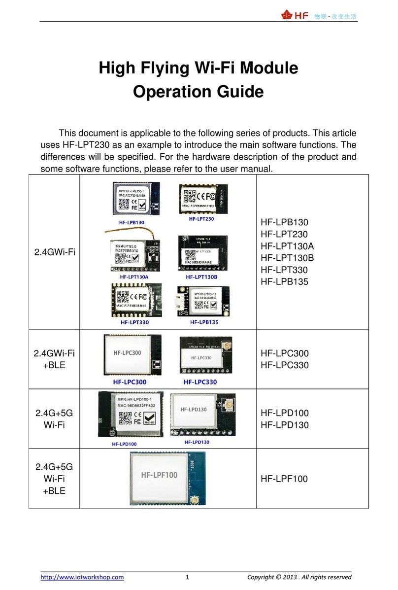
HF-LPT230 series Wi-Fi module appearance is as following.

HF-LPX30 Series Low Power WiFi Module User Manual
Shanghai High-Flying Electronics Technology Co., Ltd(www.hi-flying.com) - 9 -
Figure 1. HF-LPT230-1 and HF-LPT230-0 Appearance
1.2.1. HF-LPT230 Pins Definition
Figure 2. HF-LPT230 Pins Map
Table2. HF-LPT230 Pins Definition
Pin Describtion Net Name Signal
Type
Comments
1 SPI_MOSI SPI_MOSI O GPIO12,
2 SPI_CLK SPI_CLK I/O GPIO4,
3 SPI_MISO SPI_MISO I GPIO7
4 SPI_CS SPI_CS I/O GPIO5,
5 UART0 UART0_TX O,PU 3.3V UART0 Communication Output
GPIO2
6 UART0 UART0_RX I 3.3V UART0 Communication Input
GPIO1
7 UART0_CTS UART0_CTS I/O GPIO22, PWM0
8 UART0_RTS UART0_RTS I/O,PU GPIO23, PWM1
9 ADC ADC I/O,PU GPADC0,ADC function
10 Module Reset EXT_RESETn I,PU “Low” effective reset input. There is RC reset
circuit internally. External pull-up resistor is not
allowed.
11 Module Boot Up
Indicator
nReady O “0” – Boot-up OK;
“1” – Boot-up No OK;

HF-LPX30 Series Low Power WiFi Module User Manual
Shanghai High-Flying Electronics Technology Co., Ltd(www.hi-flying.com) - 10 -
Pin Describtion Net Name Signal
Type
Comments
GPIO24, PWM2
12 Multi-Function nReload I,PU Detailed functions see <Notes>
GPIO25, PWM3
13 Wi-Fi Status nLink O “0” – Wi-Fi connect to router
“1” – Wi-Fi unconncted;
Detailed functions see <Notes>
GPIO8
14 GPIO3 GPIO3 I/O GPIO3,PWM4
There will be 2ms output low when bootup, after
then it works as input pull high.
15 +3.3V Power DVDD Power
16 Ground GND Power
Debug RX UART1_RXD I 3.3V UART1 Debug Input
GPIO26, Leave it if not use
Debug TX UART1_TXD O 3.3V UART1 Debug Output
GPIO27, Leave it if not use
<Notes>
I — Input;O — Output
PU—Internal Resistor Pull Up;I/O: Digital I/O;Power—Power Supply
nReload Pin (Button) function:
1. When this pin is set to “low” during module boot up, the module will enter wireless
firmware and config upgrade mode. This mode is used for customer manufacture.
(See Appendix to download software tools for customer batch configuration and
upgrade firmware during mass production)
2. After module is powered up, short press this button (0.2s < “Low” < 1.5s) and loose
to make the module go into “SmartLink “ config mode, waiting for APP to set
password and other information. (See Appendix to download SmartLink V8 and
SmartAPLink APP)
3. After module is powered up, long press this button ( “Low” > 4s ) and loose to make
the module recover to factory setting.
High-Flying strongly suggest customer fan out this pin to connector or button for
“Manufacture” upgrade or “ SmartLink” application.
nReady Pin (LED) function(Low effective):
1. OS initial finished indicator. Only after this pin output low, can the UART function be
used.
nLink Pin (LED) function(Low effective):
1. At wireless firmware and config upgrade mode , this LED used to indicate configure
and upgrade status.
2. At “SmartLink” config mode, this LED is used to indicate APP to finish setting.
3. At normal mode, it’s Wi-Fi link status indicator. Output Low when STA mode connect
to router AP or other STA connect to it when in AP mode.

HF-LPX30 Series Low Power WiFi Module User Manual
Shanghai High-Flying Electronics Technology Co., Ltd(www.hi-flying.com) - 11 -
High-Flying strongly suggest customer fan out this pin to LED.
PWM function:
PWM0~PWM3 100ns period(if duty is from 0~255, then the maximum frequenry is
10M/256=39KHz), PWM4 support 800ns period.
Due to PWM pin is internal weak pull-up. So when these pins are used for LED bulb
application, suggest to add strong pull-down resistor to revent the lulb on when boot.
Note:nReload pin is also used for special function, when use this pin for PWM bulb
application and add external pull-down resistor, this will cause the module wait 1 second
when bootup(wait “space” key to etner bootloader). Contact us to provice special
bootloader in order to remove this wait time.
UART1 Debug :
1. Is used for debug log or firmware program, baud rate 921600.
2. Can be used for communication in SDK.
1.2.2. Electrical Characteristics
Table3. Absolute Maximum Ratings:
Parameter Condition Min. Typ. Max. Unit
Work temperature range -40 105 °C
Maximum soldering temperature IPC/JEDEC J-STD-020 260 °C
ESD (Human Body Model HBM) TAMB=25°C 2.5 KV
ESD (MM) TAMB=25°C 0.25 KV
Table4. Power Supply & Power Consumption:
Parameter Condition Min. Typ. Max. Unit
Operating Supply voltage 2.9 3.3 4.2 V
Supply current, peak Continuous Tx 260 mA
Supply current, STA No data transfer 27 mA
Supply current, STA Continuous data transfer 35 mA
Supply current, AP 80 mA
GPIO sink current GND+0.5V 3 mA
GPIO pull current VCC-0.5V 3 mA

HF-LPX30 Series Low Power WiFi Module User Manual
Shanghai High-Flying Electronics Technology Co., Ltd(www.hi-flying.com) - 12 -
1.2.3. HF-LPT230 Mechanical Size
The size of HF-LPT230-1 and HF-LPT230-0 is the same. HF-LPT230-1 does not have IPEX connector.
HF-LPT230 modules physical size (Unit: mm)as follows:
Figure 3. HF-LPT230 Mechanical Dimension

HF-LPX30 Series Low Power WiFi Module User Manual
Shanghai High-Flying Electronics Technology Co., Ltd(www.hi-flying.com) - 13 -
FCC Statement
This device complies with Part 15 of the FCC Rules. Operation is subject to the following two
conditions:
(1) this device may not cause harmful interference, and (2) this device must accept any
interference received, including interference that may cause undesired operation.
Caution!
Any changes or modifications not expressly approved by the party responsible for compliance
could void the user's authority to operate the equipment.
FCC Radiation Exposure Statement
The modular can be installed or integrated in mobile or fix devices only. This modular cannot be
installed in any portable device, for example, USB dongle like transmitters is forbidden.
This modular complies with FCC RF radiation exposure limits set forth for an uncontrolled
environment. This transmitter must not be co-located or operating in conjunction with any
other antenna or transmitter. This modular must be installed and operated with a minimum
distance of 20 cm between the radiator and user body.
If the FCC identification number is not visible when the module is installed inside another
device, then the outside of the device into which the module is installed must also display a
label referring to the enclosed module. This exterior label can use wording such as the
following: “Contains Transmitter Module FCC ID: 2ASCVHF-LPT230-0 or Contains FCC ID:
2ASCVHF-LPT230-0 ”.
The devices must be installed and used in strict accordance with the manufacturer's
instructions as described in the user documentation that comes with the product.
When the module is installed inside another device, the user manual of this device must
contain below warning statements:
1. This device complies with Part 15 of the FCC Rules. Operation is subject to the following
two conditions:
(1) This device may not cause harmful interference.

HF-LPX30 Series Low Power WiFi Module User Manual
Shanghai High-Flying Electronics Technology Co., Ltd(www.hi-flying.com) - 14 -
(2) This device must accept any interference received, including interference that may cause
undesired operation.
2. Changes or modifications not expressly approved by the party responsible for compliance
could void the user's authority to operate the equipment.
3. Module is limited to OEM installation ONLY.
4.That OEM integrators is responsible for ensuring that the end-user has no manual
instructions to remove or install module.
5.That module is limited to installation in mobile or fixed applications, according to Part
2.1091(b).
6.That separate approval is required for all other operating configurations, including portable
configurations with respect to Part 2.1093 and different antenna configurations.
Table of contents
Other HF Wireless Router manuals
