HFE INTERNATIONAL GENPOD 70 User manual

OWNER’S
MANUAL
HFE INTERNATIONAL
GENPODTM 70
HFEDCN0418
Revision A

1
SPECIFICATIONS........................................2
SAFETY PRECAUTIONS ..............................4
FUEL REQUIREMENTS ...............................5
COMPONENT IDENTIFICATION..................6
INSTALLATION AND STARTING..................9
INSTALLATION.....................................................................................................9
THROTTLE AND ENABLE SETUP..........................................................................11
ENGINE STARTING.............................................................................................11
STARTING AGAIN AFTER FIRST START................................................................12
INTERFACE SPECIFICATIONS....................13
MAINTENANCE .......................................16
Torque Specifications........................................................................................16
Maintenance Schedule......................................................................................16
Fuel Filter Replacement.....................................................................................17
TROUBLESHOOTING................................19
MAX POWER WORKSHEET......................22
PARTS LIST..............................................25
WARRANTY.............................................26
Document Revision Table
Rev
Description of change
Revised by
Revision
Date
Approved By
Approved
Date
A
Initial Release
TWest
10/02/19
DMcclain
10/02/19
B
Peer Review Revisions
TWest
10/18/19
DRB
10/18/19
CONTENTS

2
SPECIFICATIONS
Metric
Value (SI)
Value (SAE)
Actual displacement
70 cc
4.27 in3
Momentary Peak Power @ rated
RPM
4.5 kW@ 9000 RPM
6.0 hp @ 9000 RPM
Max Continuous Power
3.71 kW@ 7000 RPM
5 hP @ 7000 RPM
Peak Torque @ RPM
5 N-m @ 7500 RPM
3.7 ft-lb @ 7500 RPM
Max Torsional Impulse
29 N-m
21.6 ft-lb
Cruise BSFC @ RPM
437 g/kW-hr @ 6000 RPM
0.72 lb/hp-hr @ 6000 RPM
Idle BSFC @ RPM
732 g/kW-hr @ 3000 RPM
1.2 lb/hp-hr @ 3000 RPM
Do Not Exceed Max RPM
9000 RPM
9000 RPM
Rated (useable) Max RPM
8300 RPM
8300 RPM
Standard Operating RPM Range
3000 - 7500 RPM
3000 - 7500 RPM
Full System Weight with mufflers
5.06 kg
11.15 lb
Full System Power to Weight
Ratio
0.9 kw/kg
0.54 hp/lb.
Nominal Current Draw (12V)
0.5 A
0.5 A
Maximum Current Draw (12V)
1 A
1 A
Rated Max CHT
130 °C
270 °F
Do Not Exceed CHT
190 °C
375 °F
CHT after warm up
93 °C
200 °F
Rated Ambient Minimum
-18 °C
0 °F
Rated Ambient Maximum
49 °C
120 °F
Nominal Dynamic Compression
8.3 bar
120 psi
Compression Ratio
8.5 : 1
8.5 : 1
Time between overhauls
300 Hrs
300 Hrs

3

4
General Safety
Read and understand this Owner’s Manual before operating your engine. You can
help prevent accidents by being familiar with the controls and observing safe
operating procedures.
Operator’s Responsibility:
1. The operator should know how to stop the engine quickly in case of an emergency.
2. A safety zone of 3 feet around the propeller should be established in which no person
or object is allowed to enter. Install a guard around the propeller when appropriate.
WARNING
1. Observe all safety precautions when working around the propeller.
2. Exhaust contains poisonous carbon monoxide, a colorless and odorless gas.
Breathing carbon monoxide can cause loss of consciousness and may lead to death.
3. Never run your engine in an enclosed space. Always allow for appropriate
ventilation.
4. Observe precaution around the muffler. The exhaust system gets hot enough to
ignite some materials.
5. Keep flammable materials away from the engine.
6. Gasoline is extremely flammable and is explosive under certain conditions. Do not
smoke or allow flames or sparks where the engine is operating.
SAFETY
PRECAUTIONS

5
Engine Oil
This engine was calibrated using Red Line 2 Stroke Racing oil at a mix ratio of 40:1. This oil
type and mix ratio should be maintained to ensure that the fuel injection system and engine
operates as designed. If Redline oil is not available, use an equivalent 2T quality two stroke
oil for best results.
Oil Brand:
Red Line
Oil Type:
2 Stroke Racing Oil
Mix Ratio: 40:1
40 parts gasoline to one part oil by
volume.
Fuel Recommendations
The engine was calibrated with standard 87 octane gasoline. Customers may use higher
octane fuel if desired. Non-leaded fuels recommended.
Leaded Fuels Warning: When using leaded fuels, the result will be shorter TBO’s as a
result of lead oxide coking on cylinder and exhaust ports. Leaded fuels will require cylinder,
piston, and port, dressing and inspection every 50 to 100 hours (depending on use case).
Cylinder dressing and cleaning should be done by a trained professional or by HFE
International.
FUEL
REQUIREMENTS

6
Note: Non-leaded fuels will not require cylinder dressing and may be used continuously until
the suggested TBO.
Figure 1. GenPodTM Connections and Components
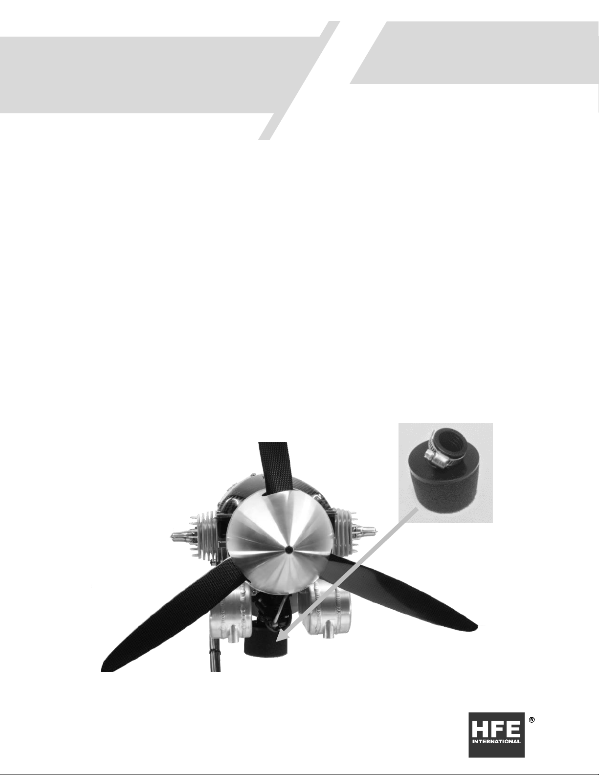
Figure 2. GenPodTM Air Filter
COMPONENT
IDENTIFICATION
Fuel Filter
Engine Connector
Generator
Connector
Fuel Connector
Air Filter
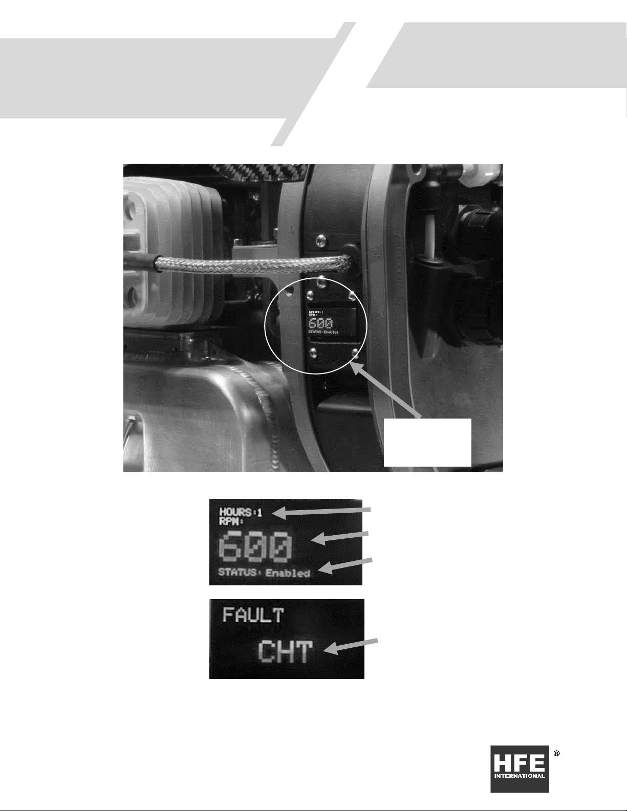
Display for
GenPodTM
Status

7
Figure 3. Intake Assembly Components
Figure 4. Intake Gasket Order
Throttle Servo
Injector
MAP Fitting
Fuel Fitting
8
Status
Display
Engine Hour Meter
Engine Speed (RPM)
Engine Status (Enabled /
Disabled)
Fault Codes will display in the
place of the standard display.
Faults:
CHT - Cylinder Head
Temperature Sensor Fault
MAT- Manifold air Temperature
Sensor Fault
TPS - No Throttle Command
given or throttle command error
Battery - Power to GenPodTM is
too high or too low. See Signal
input limits.
RPM - Crank position sensor
error.
Pump - Fuel pressure problem
9
INSTALLATION
1. Install the GenPodTM Interface to your aircraft with 4x M5 flat head screws, ensuring
that the attachment can handle up to 23 kg (50 lbs.) of thrust and vibration torque
impulses as high as 30 N-m (22 ft-lbs).
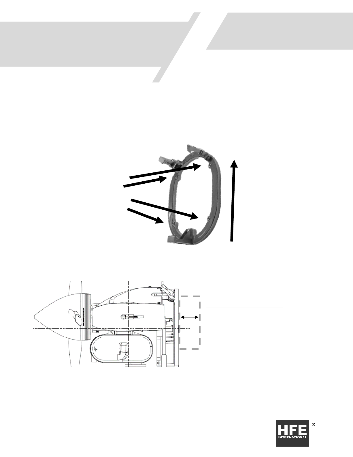
Figure 5. GenPodTM Mounting Interface
2. Verify that there is an opening in the center of the GenPodTM Interface that allows for
the back-shell of the connectors and fuel line to fit once the engine is installed. Verify
INSTALLATION
AND STARTING
Permanently Install
GenPodTM Mounting
Interface on Aircraft
with 4x M5 Flat Head
Screws
This Side Up
Allow 3 inches clearance or
more inside the vehicle for
wire strain relief
10
that there are no sharp edges that the wire harness can chafe on and that the fuel line
cannot kink when engine is installed.
3. Connect main harness and PMU inside the aircraft. You may cut and adjust the
harness inside the aircraft as needed. Use Mil Spec connectors or similar.
4. Install Engine and fuel connector to the back of the GenPodTM as shown.
5. The GenPodTM uses a Sullivan PMU and alternator. Connect the Engine as shown in
Figure 6
6. Install the GenPodTM to the Interface by resting the pin in the interface hook and latching
the two latches on top. Secure the latch with M5 flat head screws before flight.
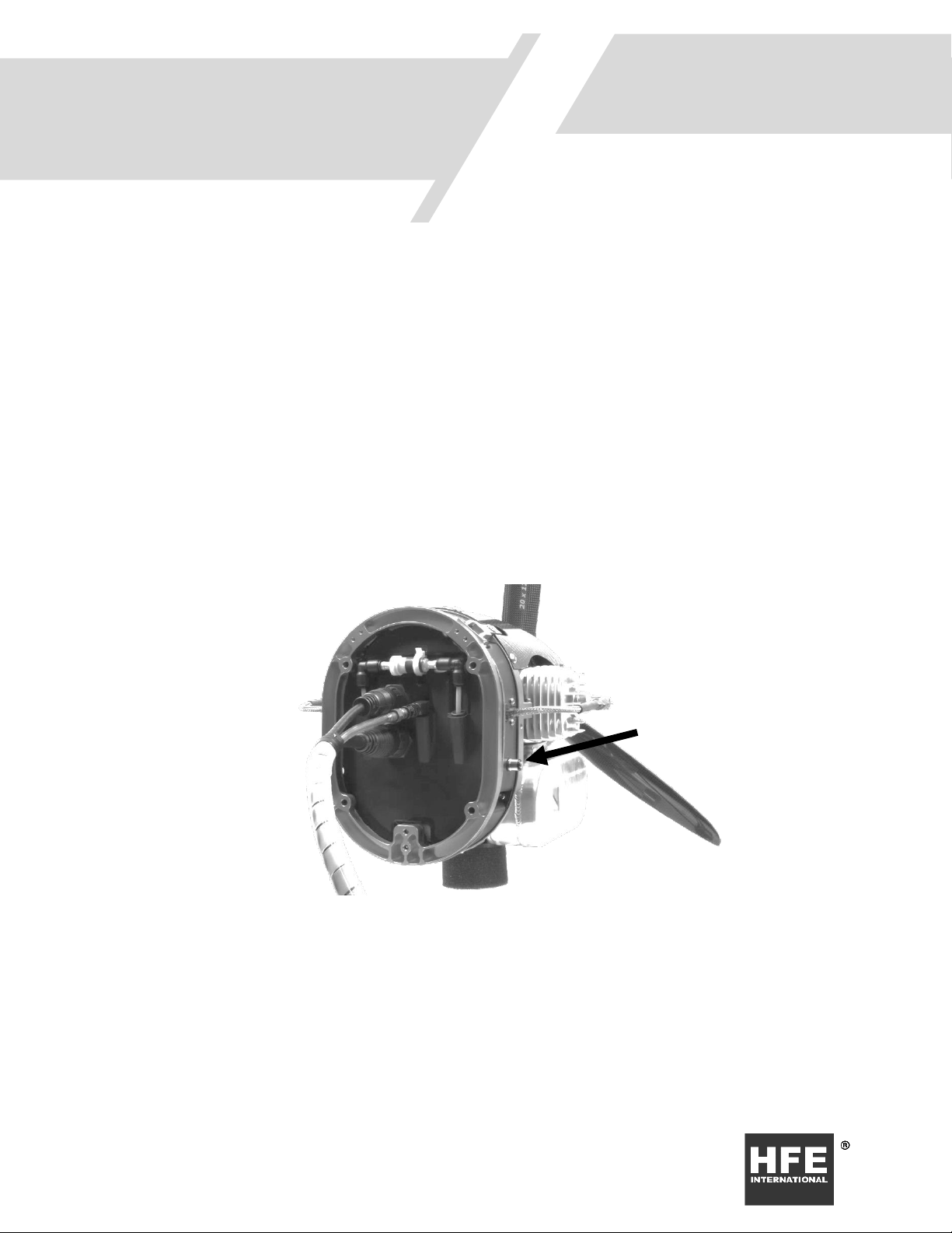
Figure 6. GenPodTM Connections.
Fuel Vent
Port

11
THROTTLE AND ENABLE SETUP
1. Throttle commands use a standard PWM signal. Expected pulse width range from 900µs
for closed throttle and 2100µs for wide open throttle.
2. (Throttle kill) When the pulse width from the receiver falls below 960µs (5% throttle),
the ECM will remove power to both the injector and ignition system thus stopping the
operation of the engine.
3. (Enable kill) Provide 5V power to the enable line, when power is removed ECM will
remove power to both the injector and ignition system thus stopping the operation of
the engine.
ENGINE STARTING
1. Verify that the throttle setting is at about 30%.
2. Prime your system for the first time by pressing and holding the fuel vent port when
the genpod power is on (Figure 6). Cycle the battery power to the Genpod in 5 second
intervals until fuel is flowing from the vent port without air. You should not have to
complete the priming process again unless the engine fuel system is allowed to run
dry or has been disconnected for any reason.
3. The engine should be started using an external hand held starter, or using a built-in
starting alternator. Flip starting is an additional option but is not
recommended due to possible injuries.
Note: The engine may struggle to run for the first few minutes as it is purging all the
air from the fuel system. This may not be evident until you go to wide open throttle.
4. Allow the engine to run for a few minutes around 3500 RPM.
5. Keep at wide open throttle for 10 seconds to verify that the air in the fuel system has
been purged. Reduce the engine speed to idle.

12
STARTING AGAIN AFTER FIRST START
1. Verify that the throttle setting is at about 30%.
2. The engine should be started using an external hand held starter, or using a built-in
starting alternator. Flip starting is an additional option but is not
recommended due to possible injuries.
3. Allow the engine to run for a few minutes around 3500 RPM.
4. Keep at wide open throttle for 10 seconds to verify that the air in the fuel system has
been purged. Reduce the engine speed to idle.

13
Signal Inputs/Outputs for GenPodTM:
Pin
Signal
Color
Description
1
TACH OUT
Brown
+5V logic-level digital output. This pin has a
maximum continuous load of ±20mA. Output
signal has a 50% duty cycle.
2
TX
Blue
RS-232 Transmit
3
CAN HI
White
CAN bus signal High
4
ENABLE
(Special feature
available on
request)
Green
Engine enable signal from Auto Pilot. A 5 volt
signal present to enable (UAV option only).
This pin has an 8mA draw. 10k pull down
resistor.
5
THROTTLE
SIGNAL
Yellow
Throttle position with logic-level input. A
Pulse Width Modulated (PWM) signal at
nominally 50Hz with ON time ranging from
900µs to 2100µs corresponding to throttle
position (0% to 100%). This pin has an 8mA
draw.
6
POWER 12V
Gray
Main power input. 10 to 14 volts. Maximum
power draw is 12 W at wide open throttle.
(11.1v 3 cell LiPo 2000ma or bigger)
7
RX
Pink
RS-232 Serial Communication Receive
8
CAN LO
Red
CAN bus signal Low
9
NC
Black
No Connect
10
GND (Main
Input)
Orange
Main Power Ground
11
GND
Purple
Serial Communication Ground Reference
12
GND
Light Green
CAN Ground Reference
13
GND
Black/White
Enable Ground Reference
14
GND
Brown/White
PWM Signal ground reference
Table I: GenPod
TM Input Connector 14 Pin
INTERFACE
SPECIFICATIONS

14
POWER MANAGEMENT UNIT NODE 1
Pin
Signal
Color
Description
1
AC IN 1
RED
3 Phase input 30VAC to 85 VAC
2
AC IN 2
YELLOW
3 Phase input 30VAC to 85 VAC
3
AC IN 3
BLUE
3 Phase input 30VAC to 85 VAC
4
BATTERY +
RED
System battery positive. 6S LiPo 24-30 VDC 150
CCA minimum for starting.
Note: LiPo battery charge circuit will enable after
engine is running.
5
BATTERY -
BLACK
System battery negative.
6
EXTERNAL +
RED
28V external input. (shore power) Do not exceed
32VDC.
7
EXTERNAL -
BLACK
External input ground.
POWER MANAGEMENT UNIT NODE 2
Pin
Signal
Color
Description
1
START +
GREEN
5V Signal indicates start.
2
START -
BLACK
Start signal ground reference
3
STATUS +
RED
TTL status signal indicates active rectification.
4
STATUS -
BLACK
TTL status signal reference ground
POWER MANAGEMENT UNIT NODE 3
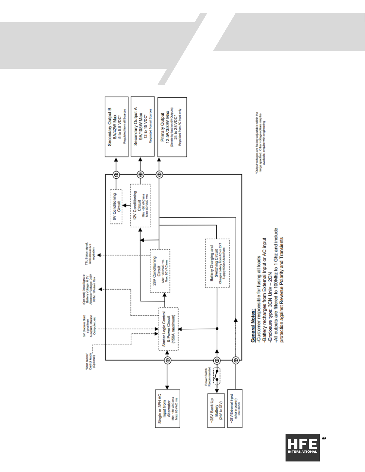
*NOTE: Primary, Secondary, and Tertiary outputs can be adjusted, within the range specified, based on
customer requirements.
Pin
Signal
Color
Description
1
PRIMARY +
RED
Primary Output 24 to 28VDC* de-rated by 6V load
on outputs. 12.5A/350W maximum output.
Regulated from AC input only. Engine must be
running for this output to function.
2
PRIMARY -
BLACK
Primary Ground Reference
3
SECONDARY +
RED
Secondary output = 12 to 15VDC* with 9A/108W
maximum output. This output is powered at all
times when battery is connected to PMU.
4
SECONDARY -
BLACK
Secondary Ground Reference
5
TERTIARY +
RED
Tertiary output = 5 to 6.5VDC* with 8A/42W
maximum output. This output is powered at all
times when battery is connected to PMU.
6
TERTIARY -
BLACK
Tertiary Ground Reference
15

16
Torque Specifications
Table 2. Torque Specifications
Description
Torque
Type
Spark Plug
10 N-m (90 in-lb)
NGK CM-6
Prop Bolts
7.3 N-m (65 in-lb)
M5 x 70 mm
Spinner Bolts
3.4 N-m (30 in-lb)
M5 x 120 mm
Muffler Bolts
6.8 N-m (60 in-lb)
M5 x 20 mm
Throttle Body Mounting Bolts1
2.3 N-m (20 in-lb)
M5 x 40 mm
Cylinder Bolts
8 N-m (70 in-lb)
M5 x 13 mm
Crank Case Bolts
8 N-m (70 in-lb)
M5 x 20 mm
Air Filter Torque
0.6 N-m (5 in-lb)
HFE0857
1Caution: Care must be taken to not over tighten the throttle body mounting bolts. Over
tightening can distort and damage the injected molded reed valve parts, rubber gaskets, and
throttle body.
Table 3. Spark Plug Gap
Spark Plug Gap
0.38mm to 0.5mm (0.018 to 0.020 inch)
Maintenance Schedule
Table 4. Maintenance Schedule
Item
Before
Each Flight
Every 50
Hours
Every 100
Hours
Every 300
Hours
Engine Oil Pre-Mix
X
Spark Plug Check/Adjust
X
Spark Plug Replace
X
Air Filter Check/Clean
X
Air Filter Replace
X
Fuel Filter
X
HFE OEM Maintenance
X
MAINTENANCE
17
Fuel Filter Replacement
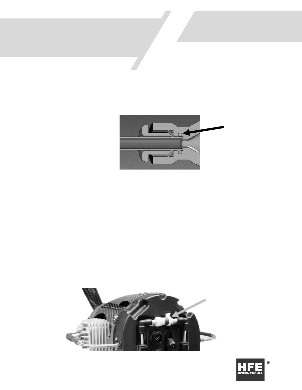
Figure 7. Push-to-Connect Seal
The GenpodTM is supplied with 2 filters: One 250 micron filtration element that is green and
one 48 micron filtration element that is blue. Fuel filters are designed to be installed with a
push to connect fitting. When installing the fuel filter make sure the push to connect is
pushed all the way down to the seal as shown in Figure 7.Also verify that the end of the
tube is cut perpendicular and smooth without flashing that may damage the O-ring seal or
prevent sealing.
1. Install the green fuel filter between the quick disconnect and the aircraft fuel tank.
2. The blue filter is part of the GenPodTM and can be found on the back bulkhead. It
resides between the fuel pump and the engine. See Figure 1 for location
Seal O-ring
48µ Fuel Filter
18
Air Filter Replacement
WARNING: Air filter installation is critical for protecting the throttle body from foreign
objects and dust that may jam the throttle barrel. Make sure the air filter is installed at all
times!
Replace air filter as needed by unscrewing the hose clamp and pulling the filter off of the
throttle body. Re-install the new filter. Do not over-tighten the hose clamp or the rubber
may tear. Follow torque specification in Table 2.
Only use OEM air filter PN HFE0857.
Make sure to rotate the air filter on the throttle body until it does not contact the muffler
surface.

19
Engine Does Not Start
No spark at spark plug(s)
Fault
Potential Cause
Corrective Action
Power
GenPodTM power is not 12 V or does
not have enough current capacity
when engine is cranking
Repair or diagnose Power Supply.
Verify GenPodTM connector is fully
seated.
Enable
Enable signal is not referencing
system ground
Tie autopilot ground to GenPodTM
system ground.
Enable signal is not 5V
Change enable voltage to 5 V
Throttle Position below 5%
Increase throttle position above 5%
Spark Plug
Gap not correct
Adjust per Table 3
Wet Spark Plug Electrodes
Remove plugs and let cylinder and
plugs dry.
Carbon Deposit on Electrodes
Replace spark plugs
Insulator failure or cracked insulator
Replace spark plugs
Burned electrodes
Replace spark plugs
Ignition
Ignition cap corroded or worn
through plating where it contacts
spark plug hex.
Return GenPodTM to HFE
International for repair
Ignition Coil Failure
Return GenPodTM to HFE
International for repair
Ignition Power
Return GenPodTM to HFE
International for Repair
TROUBLESHOOTING
Table of contents
Popular Engine manuals by other brands


Desert Aircraft
Desert Aircraft DA100 owner's manual

Bestway
Bestway HYDRO-FORCE 65043 Safety instructions

3T-Components
3T-Components 3T-MOTORS 3T35-R Installation & operating instructions

MTHTrains
MTHTrains F-3 POWERED B-UNIT Engineer's guide

Nanni
Nanni T4.155 seriers instruction manual

Powerhorse
Powerhorse 750122 owner's manual