HG7AN Antenna Analyzer plus User manual

User manual
/ verzió 1.0 /
Budapest, 2017

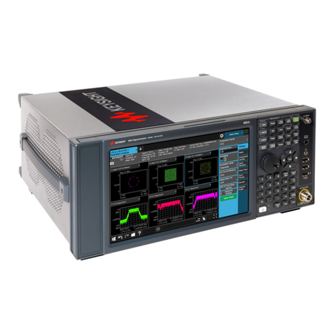
"Antenna Analyzer plus" is a multifunctional measuring instrument, most useful for
amateur radio activity. Its size allows you to easily take it for relocation as well. The
panel size is 115 x 75 mm fitting into a small box of
size eg. 125 x 80 x 25 mm. Its main function is put
into effect by the two RF impedance meters - called
together the antenna analyzer - which can measure
phase true complex impedance between the main
antenna poles, ranging
from 100kHz to
200MHz and 425MHz
to 445MHz. Numeric
results are also displayed graphically. In addition to the
detailed measurement of antenna parameters, it can be
used as an inductance and capacitance meter as
well, with which you
can measure parts
from 10nH or 1pF. Another interesting feature
available is
spectrum display
function, with
which you can
visualize the full
output spectrum
of the transmitter within the whole 100kHz to
200MHz and 425MHz to 445MHz frequency
interval.
Furthermore, the device includes a dual-channel
signal generator, which can produce sine signal from 100Hz to 200MHz and 425MHz
to 445MHz, freely set for the two independent channels
with a frequency resolution of 1 Hz. Moreover, the
relative phase shift between signals of the two channels
can be controlled by 1 degree increments from 0 to 360
degrees. Perhaps the most interesting part of the
instrument is the
control and display of
measurement results.
On the instrument
itself, there is no
display and no
controls, so it can be
placed directly on
the antenna base point while remote
controlled from a distance up to 50m, including
evaluation of the results. Control of the instrument is possible using any WiFi
enabled device with installed web browser. This could be notebook, tablet or even a
smartphone, and the solution adopted is "platform" independent, so it should not
matter if the controlling device is running Windows, Linux, Android or iOS operating
system.

TECHNICAL DATA:
Version 1.
Synthesizer: DDS with 1Hz resolution
Power: 3.7V/1500mA Li-Ion Battery
Frequency range: 100KHz - 200MHz
Operation time: ~4.5 hours
Phase: 0° –360°
Charge: 5V/400mA
Measured result range:
Charge time: ~4 hours
Complex impedance: 1Ω –1000Ω
Interface: 802.11g Wi-Fi certified
transceiver
Phase: -90° - 90°
AD converter: 12bit
Capacitance: 1pF –10nF
Size: 125x80x25 mm
Inductance: 10nH –100uH
Weight: 170g with battery
Version 2.
Synthesizer: DDS with 1Hz
resolution
Power: 3.7V/1800mA Li-Ion Battery
Frequency range: 100KHz - 200MHz
425MHz - 445MHz
Operation time: ~5 hours
Phase: 0° –360°
Charge: 5V/400mA
Measured result range:
Charge time: ~4.5 hours
Complex impedance: 1Ω –1000Ω
Interface: 802.11g Wi-Fi certified
transceiver
Phase: -90° - 90°
AD converter: 16bit
Capacitance: 1pF –10nF
Size: 125x80x25 mm
Inductance: 10nH –100uH
Weight: 175g with battery
Front layout:
A: Power on/off switch
B: Charging connector. Charge the antenna analyzer in switched off state!
C: Charge display LED
D: Power on display LED
E: Operation display LED
F: Antenna connector and signal generator channel 1 output
G: Signal generator channel 2 output

Warnings:
-Be sure that your antenna has no stored electrostatic charge before trying to
connect to the antenna analyzer.
-Do not connect the antenna analyzer to antenna in a stormy weather.
-Do not left the antenna analyzer connected to antenna. Electrostatic discharge can
damage analyzer even if it powered off.
-Do not connect analyzer to transmitter RF-Output. RF signal from transmitter
immediately damage the antenna analyzer.
-Please observe a correct polarity when you charge the antenna analyzer from
external DC source.
Requirements for the control device:
-WIFI 802.11g compatible
-Operating sytem with internet browser
/Windows 7 or newer, or Android 4 or newer, or iOS7 or newer, linux (not
tested)/
Connection:
-WIFI SSID: Analyzer http://192.168.1.1
-Password (WEP-13 characters): antenna123456
-Web address: http://192.168.1.1

FUNCTIONS
Antenna analyzer:
A: Choose a band or type the center frequency in the input field
B: Set the scan bandwidth
C: Choose the function of the frequency-tuning knob and the step value
D: Frequency-tuning knob. You can use the frequency-tuning knob to set the center
frequency or scan bandwidth
E: Select the measured value that the „blue”graph will show
F: Select the measured value that the „red” graph will show
G: Press the Start button and wait for the result of the measurement
H: Read the result from the the graph
I: Click on the graph to show the measured values in that point
J: Zoom-out selection button
K: Zoom-in selection button
L: Click on this stripe to zoom-in or zoom-out the graph
M: Type the name of the measurement in the input field. If you press the Save button
your measurement will be saved with the given name
N: Press the Save button if you want to save the result
O: Press the Load button if you want to load a saved result
P: Display of the battery value
Q: Press the Smith Chart button if you want to see the impedance curve of the
measurement

Smith Chart:
A: Read the result from the the graph
B: Analysis results:
-minimum SWR value in the measured frequency range
-complex impedance value at the minimum SWR value
-start frequency of the bandwidth
-end frequency of the bandwidth
-bandwidth of the measured antenna
-quality of the measured antenna
C: Press the Freq Graph button to return to the frequency graph

SIMPLE (measurement on a single frequency):
A: Choose a band or type the frequency in the input field
B: Choose the step value of the frequency-tuning knob
C: Frequency-tuning knob. You can use the frequency-tuning knob to set the
frequency
D: Press the Start button and wait for the result of the measurement
E: Read the result
F: Display of the battery value
G: Press the Back button to return to the main page

L/C (LC meter):
A: Follow the instructions and press the Start button
B: Read the result
C: Display of the battery value
D: Press the Back button to return to the main page
Tips and tricks: For more accurate measuring of a capacitance or inductance, make a
very short measuring cable and calibrate the analyzer with OSL method at the end of
the measuring cable. Afterwards connect the capacitance or inductance at the end of
the measuring cable and start the measuring.
Do not forget to recalibrate the Analyzer or load the default calibration value before
measuring an antenna!

SPECT (Spectrum display):
A: Choose a band or type the center frequency in the input field
B: Set the scan bandwidth
C: Choose the function of the frequency-tuning knob and the step value
D: Frequency-tuning knob. You can use the frequency-tuning knob to set the center
frequency or scan bandwidth
E: Press the Start button and wait for the result of the measurement
F: Read the result from the the graph
G: Display of the battery value
H: Press the Back button to return to the main page
Warnings: Do not connect the antenna analyzer to transmitter RF-Output. RF
signal from transmitter immediately damage the antenna analyzer!!!

SIGNAL (Signal generator):
A: To switch on or off the Channel 1 output press the eligible button
B: To switch on or off the Channel 2 output press the eligible button
C: Set the phase value between the channels
D: Type the Channel 1 frequency in the input field
E: Type the Channel 2 frequency in the input field
F: Offset function selection buttons for Channel 1
G: Offset function selection buttons for Channel 2
H: Type the Offset 1 and Offset 2 frequency in the eligible input fields
I: Choose the step value of the tuning knob
J: Choose the function of the tuning knob
K: Tuning knob. You can use the tuning knob to set the eligible frequency or phase
value
L: Lock Button. You can link the Channel 1 and Channel 2 frequencies when you use
the tuning knob (both frequencies will change with the same values)
M: Display of the battery value
N: Press the Back button to return to the main page

Setup:
A: Load the original impedance calibration
B: Impedance calibration. You can calibrate the antenna analyzer with your
„open/short/load” impedances. The „load” impedance must be 50 ohm. During the
calibration follow the instructions
C: Load the original frequency calibration
D: Frequency calibration. Press the start button to switch on the test frequency on the
Channel 2 output
E: Measure the test frequency on the Channel 2 output with an accurate frequency-
counter and write the result [Hz] in the input field
F: Press the Save button to store the new calibration value
G: WIFI seteup. Write the new WIFI-SSID in the input field. If you leave the field
empty, the previous text will remain as the WIFI-SSID
H: Write the new password in the input field. The password must be 13 characters
long and use numbers or letters from the English alphabet! If you leave the field
empty, the previous text will remain as the password
I: Press the Save button to store the new WIFI-SSID and/or password
J: Press the Back button to return to the main page
I'm happy to provide you with further information, please contact me at:
hg7an.zoli@gmail.com
WWW.HG7AN.COM
Table of contents

