HH Electronics SP48 User manual

1
HH
Speaker Processor
User Manual

2
INTRODUCTION ............................................................................................................................4
FEATURES.................................................................................................................................. 4
GETTING STARTED .......................................................................................................................5
CONNECTING THE SP48..............................................................................................................6
Passive TNA System.................................................................................................................. 6
Passive TNi-C6 System ............................................................................................................. 7
Active TNA System.................................................................................................................... 8
Mixed TNA System.................................................................................................................... 9
SP48 PROCESSOR OVERVIEW...................................................................................................10
REAR PANEL ............................................................................................................................10
FRONT PANEL.........................................................................................................................11
Encoders, Enter and ESC buttons.........................................................................................12
FACTORY RESET.....................................................................................................................13
UTILITIES .......................................................................................................................................14
SYSTEM UTILITIES...................................................................................................................15
Delay Units..........................................................................................................................15
Set Default Value................................................................................................................15
Firmware Version ...............................................................................................................15
PROGRAM UTILITIES ..............................................................................................................15
Recall a Program ................................................................................................................15
Save a Program ..................................................................................................................15
Delete a Program...............................................................................................................15
INTERFACE UTILITIES.............................................................................................................16
Interface Setup ...................................................................................................................16
SECURITY UTILITIES................................................................................................................17
Show Parameter .................................................................................................................17
Lock Unit .............................................................................................................................17
Change Password ..............................................................................................................17
Lock With Password...........................................................................................................17
EDITING ........................................................................................................................................18
INPUTS A/B/C/D .....................................................................................................................19
Name ...................................................................................................................................19
Noise Gate ..........................................................................................................................19
Gain .....................................................................................................................................20
Delay....................................................................................................................................20
Polarity.................................................................................................................................20
RMS Compressor ...............................................................................................................21
EQ Bypass ...........................................................................................................................22
30 Band EQ [EQ-01 -> EQ-30]..........................................................................................22
OUTPUTS 1~8 .........................................................................................................................24
Name ...................................................................................................................................24
Routing Page ......................................................................................................................24
Gain .....................................................................................................................................24
Delay....................................................................................................................................24
Polarity.................................................................................................................................25
LIMITER................................................................................................................................25

3
HPF.......................................................................................................................................26
LPF .......................................................................................................................................26
EQ Bypass ...........................................................................................................................27
7 Band EQ [EQ-01-> EQ-07].............................................................................................27
LINKING INPUTS AND OUTPUTS..........................................................................................28
USING THE CONTROL APP ........................................................................................................29
Installation................................................................................................................................29
Connecting to Device.............................................................................................................31
USB ......................................................................................................................................31
RS485...................................................................................................................................32
Multiple connections .........................................................................................................33
DEMO MODE .....................................................................................................................35
Rout Screen..............................................................................................................................35
Level Screen ............................................................................................................................37
Input Screen.............................................................................................................................38
Output Screen .........................................................................................................................39
Editing channel names...........................................................................................................40
View All Graph.........................................................................................................................40
MENU ..................................................................................................................................41
LOAD...................................................................................................................................41
SAVE ....................................................................................................................................41
STORE..................................................................................................................................41
RECALL................................................................................................................................42
COPY IN ..............................................................................................................................42
COPY OUT ..........................................................................................................................42
DEFAULT.............................................................................................................................43
USER ....................................................................................................................................43
LOCK ...................................................................................................................................43
PASSWORD ........................................................................................................................43
ABOUT ................................................................................................................................44
TECHNICAL SPECIFICATIONS...................................................................................................45
DIMENSIONAL DATA (in mm)...............................................................................................46
SAFETY INFORMATION..............................................................................................................47

4
The HH Electronics SP48 is a fully featured 4-IN/8-OUT digital speaker management
system. Featuring 4 analogue inputs and 8 analogue outputs, each managed by a
powerful DSP Engine.
The four input channels provide 30-band parametric EQ, Noise Gate, up to 420ms Delay
and RMS Compressor.
Each of the 8 outputs offers 7-band parametric EQ, crossovers with slopes from 6dB/oct
up to 48dB/oct, 128ms of Delay and Peak Limiter settings.
Easy setup is assured with intuitive front panel controls and an interactive LCD display for
local setup, or a dedicated PC control interface for remote monitoring and configuration
via USB or RS485.
The SP48 loudspeaker processor is the perfect counterpart to any HH speaker system,
suitable in an array of applications, such as live sound, indoor/outdoor events, public
address, theatrical performance, and touring.
It also comes pre-loaded with expertly created audio pre-sets for use with the TNA line
array system, for easy setup straight out of the box.
FEATURES
•High performance 4 input, 8 output loudspeaker processor.
•High quality 24bit AD/DA audio converters.
•96bit DSP processor precision.
•USB port for simple programming and setup.
•Linkable inputs and outputs for easy stereo configuration.
•Switched mode power supply with 100-240V worldwide operation.
•1U rack height

5
To quickly get started using the HH SP48 follow the following steps:
1. Make all initial connections with the power OFF on all equipment. Ensure any
volume, level, or gain controls are at minimum.
2. Connect your signal source output to the inputs of the SP48.
3. Connect outputs 1-8 from the SP48 to the inputs of your power amplifiers or
powered loudspeakers.
4. Starting at the signal source, turn on equipment.
5. As soon as the SP48 is turned ON the device model name will appear in the LCD
screen
HH SP 48
Speaker Management
6. A status bar will show the progress of the SP48 initialization process
HH SP 48
7. After the SP48 has finished it’s boot up sequence, select the preset to best match
your system setup.
HH SP48
Default Preset
HH SP48
P01:TNA Full System
8. Turn on power amplifiers, powered loudspeakers, and the rest of the system.
9. Un-mute the input and output channels of the SP48.
10. Turn up the signal source until audio is heard through the system.

6
Here are some example system connections for the SP48.
Passive TNA System
In this example, the SP48 is setup to drive a passive TNA system using HH M-Series
amplifiers. The four inputs come from a signal source such as a mixer or media stream.
The first two outputs are driving the two TNA-1800s subs with a LF crossover. The next
two are driving four TNA-1200S with two per channel for the mid band frequencies.
Another two are driving 8 TNA-2051s and the last two are driving two TNi-W8PROs for
balcony fills.

7
Passive TNi-C6 System
This setup shows the SP48 connected to 4 M-series amplifiers, which in turn are each
connected to 10 TNi-C6s. The system shown here has various uses such as bars, cafes or
offices and can be spread over multiple rooms.

8
Active TNA System
This example shows the SP48 driving into an Active TNA system with powered speakers.
The first two channels are used to drive the TNA-2120SA MF to HF loudspeakers, these
would receive a full range signal as the on-board DSP will handle crossover frequencies,
this gives the SP48 more freedom for EQ adjustments to fit the room environment. The
last six channels are used to drive six TNA-1800SA active subwoofers. Having
independent channels for each sub-woofer allows for precise phase alignment.

9
Mixed TNA System
In this example the SP48 is setup for a mix of powered and passive loudspeakers. Two
outputs are used to drive two TNA-1800SA powered sub-woofers. This leaves the
remaining six outputs to drive 6 TNi-W8Pro via three M-1500A amps. This system could
be extended with multiple subs and TNi-W8PROs to easily cover a bar or club venue.
10
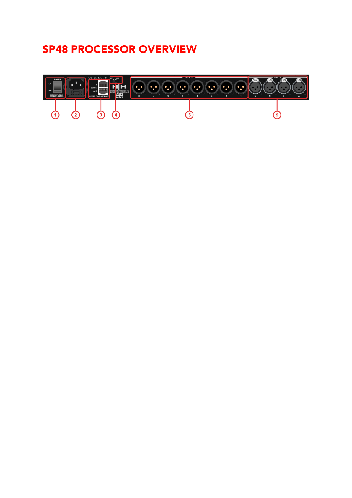
REAR PANEL
1. POWER SWITCH
Turns the HH SP48 on and off. When powering on or off the unit, the outputs and inputs
will mute to avoid unwanted pops or noise, but it is still recommended to turn off / mute
any power amplifiers or active loudspeakers connected to the SP48 before power cycling
the unit.
2. MAINS INLET SOCKET & FUSE
This is where to connect the IEC power cable included with the SP48. The SP48 uses a
SMPSU which allows for 100-240V~ Worldwide AC operation.
The FUSE is accessible from the holder. Only replace the fuse with the correct type and
rating - T800mA L 250V
3. RS485 Connections
IN and OUT ethernet connections for RS-485 remote control and linking several units. Up
to 32 SP48 can be connected in the same network. The RS-485 section also has its own
GND lift switch if ground loop hum is induced via the RS-485 connections.
4. GND/LIFT
If you are getting ground loop hum from the RS-485 connections, you can use the
GND/LIFT in attempt to remedy it.
5. XLR OUTPUTS
Eight line-level balanced male XLR outputs for each of the processor’s channels. Connect
these to inputs of power amplifiers and/or active loudspeakers.
6. XLR INPUTS
Four line-level balanced female XLR inputs for input channels A, B, C and D. Connect
these to the main mixer outputs or other audio source.

11
FRONT PANEL
7. LCD
The main LCD display works in conjunction with the NAV controls and can be used to
access and edit the local SP48 configuration settings. This is useful if not using the control
app to configure the processor or to make quick adjustments.
8. PM1/ENTER
The [PM1/ENTER] control is a rotary encoder used for editing parameter values as well as
a button to enter submenus and confirm operation changes.
9. PM2/ESC
The [PM2/ESC] control is a rotary encoder used for editing parameter values as well as a
button to leave submenus and cancel operation changes.
10.PM3/UTILITY
The [PM3/UTILITY] control is a rotary encoder used for editing parameter values as well
as a button to enter the sub-menus for setting the general characteristics of the processor
11.EDIT/MUTE BUTTONS
The 12x MUTE / EDIT buttons have two modes of operation. They allow selection for
editing and control the mute status of the 4 inputs and 8 outputs.
A short press selects the relevant input or output channel for editing. This will illuminate
the LED of the selected channel blue; a second press will deselect the channel and bring
it out of edit mode. It is possible to select multiple inputs or outputs at once for
simultaneous editing.
A long press enables or disables the mute for the input or output channel. This will
illuminate the LED red to indicate the relevant channel is muted. Press and hold until the
MUTE LED is cleared to enable the channel again.
12.EDIT/MUTE LEDs
12 LEDs referring to each input or output. A blue light indicates the selected channel/s are
being edited. A red light indicates the selected channel/s are muted.
13.METERS
The METER LED displays show current signal level for the input and output. For optimal
headroom these meters should remain green. The occasional peak enabling the yellow

12
“LIMIT” LED is viewed as ok. Constant illumination of the LIMIT LED or the red CLIP LED
shows the signal level is too high and should be lowered.
Note Internal Gain and EQ settings can also cause the signal to increase in level, in general
it is better to cut than to boost excessively
The input meters show:
CMP, CLIP, +15dBu, +9dBu, +3dBu, 0dBu, -25dBu
The output meters show:
LIMIT, CLIP, +15dBu, +9dBu, +3dBu, 0dBu, -25dBu
14.USB
For more convenient control of the SP48, you can use any Microsoft Windows® based PC
by connecting via the USB cable supplied.
Encoders, Enter and ESC buttons
The HH SP48 is equipped with 3 Relative Encoders, PM1/ENTER, PM2/ESC and
PM3/UTILITY. These encoders allow you to navigate the user interface and edit sections of
the processor. The PM1/ENTER rotary encoder is used to navigate menus and sub-menus
as well as confirm changes. The PM2/ESC and PM3/UTILITY encoders allow editing of
selected parameters as well as exiting/cancelling settings and entering the utility menu.

13
FACTORY RESET
In the event of the password being lost or any other reason the user may require the unit
to be reset to the original factory settings. The FACTORY RESET will clear all settings of
the HH SP48 and return the device to the original factory setting.
Note: A factory reset of the HH SP48 will mean any user settings or previously
stored information will be permanently lost.
To perform a factory reset:
1. Whilst the unit is off, press and hold the ENTER, ESC & UTILITY buttons.
2. Power on the unit whilst holding these buttons.
3. The following LCD screen will appear:
Please Wait.....
Memory Reset
4. Release the buttons and wait for the factory reset to complete.
Regular operation as a completely new unit will resume once complete.

14
There are 4 utility menus to choose from:
•System Utilities
•Program Utilities
•Interface Utilities
•Security Utilities
To access any of the utility menus press the UTILITY button to open the menu.
Use the NAV/PM1 control to navigate the menu and sub-menus. ENTER and ESC buttons
can be used to enter sub-menus or return to the home screen.

15
SYSTEM UTILITIES
Delay Units
Allows to select the measurement unit to be used for the Delay. The options are Time (in
milliseconds) or Distance (in meters).
PM2 & PM3 –Change unit, Time(ms) and Distance(m).
Set Default Value
Resets the current preset to the factory defaults.
Firmware Version
Displays the current Firmware of the HH SP48.
PROGRAM UTILITIES
This sub-menu allows you to access options related to the management of presets in the
HH SP48. From this menu you can Recall, Save and Delete stored presets.
Recall a Program
Allows loading of preset programs and settings. The HH SP48 can store up to 24 presets
in the onboard memory. PM1 will scroll through available presets, if no user presets are
found the display screen will show “No Stored Programs”.
Press ENTER to recall a user preset and then ENTER again to confirm recalling the preset.
The unit will mute whilst recalling a preset. More presets are available on our website.
Save a Program
Allows to save the current settings into a preset slot. Use PM1 to scroll to the required slot
to store the current settings. Selecting a slot with an existing user preset is possible,
though a confirmation screen will appear to warn of overwriting.
After ENTER is pressed a preset name is required. Use PM1 to select the character
position, PM2 & PM3 to select the character. Press ENTER once name entry is complete,
and press ENTER again to confirm.
Delete a Program
Allows to delete any of the stored presets on the HH SP48. Use PM1 to scroll to the preset
to delete, and press ENTER to delete the selected preset.
Warning: Deletion of presets is permanent and cannot be undone.

16
INTERFACE UTILITIES
The INTERFACE sub-menu is for remote control settings [USB or RS-485].
Interface Setup
Allows you to define the remote-control interface [RS485] to be used for controlling the
SP48.
If you would like to connect more than one unit under the RS485 mode, use PM2/PM3 to
set any ID from 1 to 32 and confirm with enter to assign the connected units.
The remote control is available via the rear RS485 connector.

17
SECURITY UTILITIES
A selection of security options to protect settings and to avoid tampering when the unit is
used in public installations or for security systems.
Show Parameter
Press ENTER button again and use the PM2 or PM3 encoders to select between “be
shown” or “not be shown” options. Choosing the “be shown” option means that once the
unit is locked, you cannot access parameter editing features, but they will be displayed on
the LCD screen. Choosing the “not be shown” option means that once the unit is locked,
the parameters will not be shown at all.
Lock Unit
Allows the unit to be locked so no parameters can be edited or modified.
[ON] When lock is selected from the menu, the unit will be locked, and the lock menu
automatically exits. The screen will revert to the default showing the current configuration.
Additionally, a key icon will appear to indicate the SP48 is locked.
[OFF] Default setting. Parameters can be edited, and mutes changed.
Change Password
The SP48 can be password protected to further add security and limitations to editing
parameters. The User Password menu is used to set and change the password.
Press ENTER on the User Password menu to start. Use PM2 to move between locations
and PM3 to choose the character. First, enter the existing password (the default is
[000000]) and press ENTER again. Now input the new required password, press ENTER
and re-enter the new password to confirm, pressing ENTER for the final time will update
the stored password.
Lock With Password
Like “Lock Unit”, allows the unit to be locked so no parameters can be edited or modified.
In addition, the unit cannot be unlocked without a password input.
Press ENTER on the [Lock With Password] menu to start. Input the password (see Change
Password section for how to change) and press enter to lock the SP48.
To unlock the unit press UTILITY and enter the password. If the password is ever lost or
the unit is locked out, a factory reset can be used to gain access back into the unit.

18
Changing parameters on the SP48 is possible via the front panel controls. The following
sections will cover the parameters available for control for both the input channels and
output channels.
On the front panel pressing any of edit buttons will allow parameter modification, a long
press with enable / disable the channel mute. Multiple parameter changes across
channels are also possible, see
LINKING INPUTS AND OUTPUTS.

19
INPUTS A/B/C/D
The HH SP48 has 4 XLR inputs best suited for line level inputs. The inputs are labelled A,
B, C and D.
On the front panel pressing any of the four-input mute/edit buttons will allow parameter
modification, a long press with enable / disable the channel mute.
The signal path for the four channels is as follows:
Name
This menu gives the possibility to assign an input channel a name with up to 6 characters.
Pressing ENTER will begin the editing process, use PM2 to select the character and PM3
to change the character. Press ENTER to confirm the new name of the input channel.
Noise Gate
The SP48 comes with a noise gate for each input channel. This can be useful for removing
any low-level input noise, such as electrical hum. Pressing ENTER will open the submenu
which contains 4 settings for the noise gate. Use PM1 to navigate the 2 pages.
Page 1 –Bypass & Threshold
[Bypass] PM2 controls the bypass setting for the noise gate. Setting the noise gate to ON
will disable the noise gate from the signal path. Toggling on and off is useful for
comparing both affected and un-affected signal.
[Thr] PM3 controls the threshold level in dBu. Signals below the threshold value will be
muted by the noise gate, signals above the threshold will be un-affected. The value range
can be from -80dBu to -50dBu.
Page 2 –Attack & Release
The attack and release settings change how quickly the noise gate re-acts to changing
signal level. The attack setting controls how fast the noise gate mutes the signal once it
drops below the threshold. The release settings controls how fast the noise gate un-mutes
the signal once it rises above the threshold.
[Rel] The release setting for the noise gate is set by PM2. Value range is 10ms –1,000ms.
[Atk] The attack setting for the noise gate is set by PM3. Value range is 1ms –1,000ms.

20
Gain
Each input channel has independent gain control. Press ENTER to being editing the Gain.
PM2 will change the gain in increments of 1.0dB and PM3 will change the gain in
increments of 0.1dB. Press ESC to exit the gain editing mode.
[Gain] Value ranges from -18dB to +12dB in 0.1dB steps.
Delay
The SP48 input delay is useful for time aligning multiple system components together,
time aligning the system to live instruments, time aligning systems with videos and more.
The delay setting can be displayed in two formats: distance (in meters) and time (in
milliseconds). The display unit is set in the [SYSTEM UTILITIES > Delay Units] menu.
PM2 controls the coarse adjustment of the delay time, and PM3 controls the fine
adjustment of the delay time. The available delay ranges are:
Time: 0ms ~ 420.9984ms
Distance: 0m ~ 143.139m
Polarity
The phase of the SP48 inputs can also be altered. Press ENTER to change the setting, and
then the polarity of the input can be set to either
[Normal] 0˚ phase shift
[Invert] 180˚ phase shift
Table of contents


