CHD 7-702 User manual
7
Module 7-702 v. 1.0
USER GUIDE
© 2014 CHD Elektroservis

Stereo Bucket Brigade FX Unit
Module 7-702 v. 1. 0
Copyright © 2014 CHD Elektroservis. All rights reserved.
No part of this publication may be reproduced in any form without the written permission of CHD Elektroservis.
2
Content
page
1. Main features . . . . . . . . . . . . . . . . . . . . . . . . . . . . . . . . 3
2. Module functions . . . . . . . . . . . . . . . . . . . . . . . . . . . . . . . 4
3. Connection the module to the system . . . . . . . . . . . . . . . . . . . . . . 5
4. Operation . . . . . . . . . . . . . . . . . . . . . . . . . . . . . . . . . . 5
4.1. “Audio” block . . . . . . . . . . . . . . . . . . . . . . . . . . . . . . . . 5
4.2. “Delay” block . . . . . . . . . . . . . . . . . . . . . . . . . . . . . . . . 5
4.3. “Modulation” block . . . . . . . . . . . . . . . . . . . . . . . . . . . . . . 6
5. User setting examples . . . . . . . . . . . . . . . . . . . . . . . . . . . . . 6
6. Technical parameters . . . . . . . . . . . . . . . . . . . . . . . . . . . . . 7
7. Warranty conditions . . . . . . . . . . . . . . . . . . . . . . . . . . . . . . 7
This manual and other documentation are also available at : www.chd-el.cz
Manufacturer :
CHD Elektroservis
Nad kundratkou 27, 19000 Praha 9, Czech Republic
info@chd-el.cz
www.chd-el.cz

Stereo Bucket Brigade FX Unit
Module 7-702 v. 1. 0
Copyright © 2014 CHD Elektroservis. All rights reserved.
No part of this publication may be reproduced in any form without the written permission of CHD Elektroservis.
3
1. MAIN FEATURES
Two genuine analogue BBD circuits (2x 1024 stages)
Stereo output (incl. switchable modulation phase)
Internal LFO
Mixed output with “Dry / Wet” audio signal ratio control
External control of Delay length and modulation
Chorus, Phaser, Flanger, Vibrato, Chorus/Vibrato effects
Stainless steel front panel
Pure analogue circuitry (no DSP technology used)
Fully hand-made – each module tested and adjusted individually
OUR MISSION
Do things different
Always offer something unique and innovative not available on the market so far.
No compromises in the circuitry design
Don’t give up the sound quality for cost driven compromises.
Classic design and hi-end components
For long live and better serviceability of the devices.
Hand made in Europe
Each unit is hand made and individually adjusted for highest quality control.

Stereo Bucket Brigade FX Unit
Module 7-702 v. 1. 0
Copyright © 2014 CHD Elektroservis. All rights reserved.
No part of this publication may be reproduced in any form without the written permission of CHD Elektroservis.
4
2. MODULE FUNCTIONS
Stereo Bucket Brigade FX Unit module is designed for Eurorack modular synthesizer systems. All
controls, signal inputs and outputs are located on the front panel (see Fig. 1). Inputs and outputs use
standard mono 3,5 mm (1/8“) mini-jack patch connectors.
Fig. 1 – Module front panel
DELAY block:
[1] MANUAL – manual control
[2] EXT-CV – external CV control input
MODULATION block:
[3] +/- – modulation indicator
[4] DEPTH – modulation depth control
[5] EXT-MOD – external MOD control input
[6] Φ 0° / Φ 180° – modulation signal phase
[7] INT-MOD – internal LFO speed
AUDIO block:
[8] OVERLOAD – overload indication
[9] GAIN – input gain control
[10] INPUT – audio signal input
[11] FEEDBACK – feedback level
[12] MIX – wet / dry signal ratio
[13] OUTPUT-RIGHT – right audio channel output
[14] OUTPUT-LEFT – left audio channel output
Stereo Bucket Brigade FX Unit is based on 2 analogue delay circuits (BBD). The scheme in Fig. 2
shows the internal block structure of the module. The module is designed for stereo Ensemble,
Phaser, Chorus, Flanger and similar effects. The resulting effect depends on input voltage controls
and knob settings.
Fig. 2 – Block scheme

Stereo Bucket Brigade FX Unit
Module 7-702 v. 1. 0
Copyright © 2014 CHD Elektroservis. All rights reserved.
No part of this publication may be reproduced in any form without the written permission of CHD Elektroservis.
5
3. CONNECTION THE MODULE TO THE SYSTEM
Fig. 3 – Bus board connection
To connect the module, plug carefully the supplied
ribbon cable into the bus socket of your modular
case. The colored marking of the ribbon cable
must be at the bottom of the bus connector!
Failure to check this may result in the module or
case PSU damage! (module is not protected against
permanent incorrect polarity).
The module uses ±12V of the system only (pins Nr.
1 to 10), GATE, CV and +5V signals are not used
(see Fig. 3).
4. OPERATION
The controls and inputs/outputs are divided in three function blocks: “AUDIO”, “DELAY” and
“MODULATION”.
4.1. “AUDIO” BLOCK
The Audio block processes analog audio signals. Input signal is connected to AUDIO-IN [10] input, the
minimal input signal level for full gain is ±2,5 V
PP
. Optimal input gain level is adjustable by GAIN [9]
potentiometer so input voltage amplitude can be higher than ±2,5 V
PP
. The indication LED OVERLOAD
[8] should shortly blinked at maximum input signal level. If the LED lights permanently, the input
levels of BBD lines are overloaded and the audio signal is distorted thus.
The module outputs stereophonic signal – there are two audio outputs available OUTPUT-LEFT [14] a
OUTPUT-RIGHT [13]. Both outputs provide a signal of max ±2,5 V
PP
amplitude (accordingly to the
input signal levels and panel controls settings). This signal level conforms to standard input level +4
dB of professional amplifiers, mixers etc.
Both outputs have a mixed Dry (input) and Wet (BBD liens) signals. The required ratio of these
signals can be adjusted by MIX [12] potentiometer. In the left (DRY) position the input signal remains
unaffected, hence in the right (WET) position, the output signal comes solely from the analogue
delay lines.
It is possible to input the delayed signal from the BBD lines back at their inputs with the FEEDBACK
[11] potentiometer. The left position (MIN) eliminates the feedback completely, while the right
position (MAX) comes up to self-oscillation.
4.2. “DELAY” BLOCK
Basic time of the analogue delay lines is manually controllable by MANUAL [1] knob from approx. 4
ms (SHORT) to 25 ms (LONG). If the patch lead is connected in EXT-CV [2] input, the potentiometer
of the manual control is automatically disconnected and the delay length is controlled by external
control voltage. For full parameter range control, the external control voltage should be in the
range of 0 to +8 V. The lower control voltage enables longer delay time (0 V for LONG, +8 V for
SHORT).
Stereo Bucket Brigade FX Unit
Module 7-702 v. 1. 0
Copyright © 2014 CHD Elektroservis. All rights reserved.
No part of this publication may be reproduced in any form without the written permission of CHD Elektroservis.
6
4.3. “MODULATION” BLOCK
Basic delay time can be modulated by internal LFO or external modulation source.
If there is no jack cable inserted in EXT-MOD [5] input, the delay time is modulated by internal LFO
with triangle waveform. The speed of internal LFO can be set by INT-MOD [7] knob, in the range of
approx. 0,15 to 20 Hz.
If there is a patch lead inserted in EXT-MOD [5], internal LFO is automatically disconnected and the
delay length is modulated by external control voltage. For full modulation range, the external
control voltage should be in the range of min. ±2,5 V
PP
. External modulation source can have any
frequency and shape.
The phase of the modulation can be set for both internal and external modulation signal with the Φ
0° / Φ 180° [6] switch. The resulting stereo effect is affected. In Φ 0° position, the modulation
signal is the same for both analogue delay lines (i.e. left and right channel is modulated the same
way). In Φ 180° position, the modulation signal is inverted for one of the delay lines (i.e.
modulation of the left and right channels are in opposite phases).
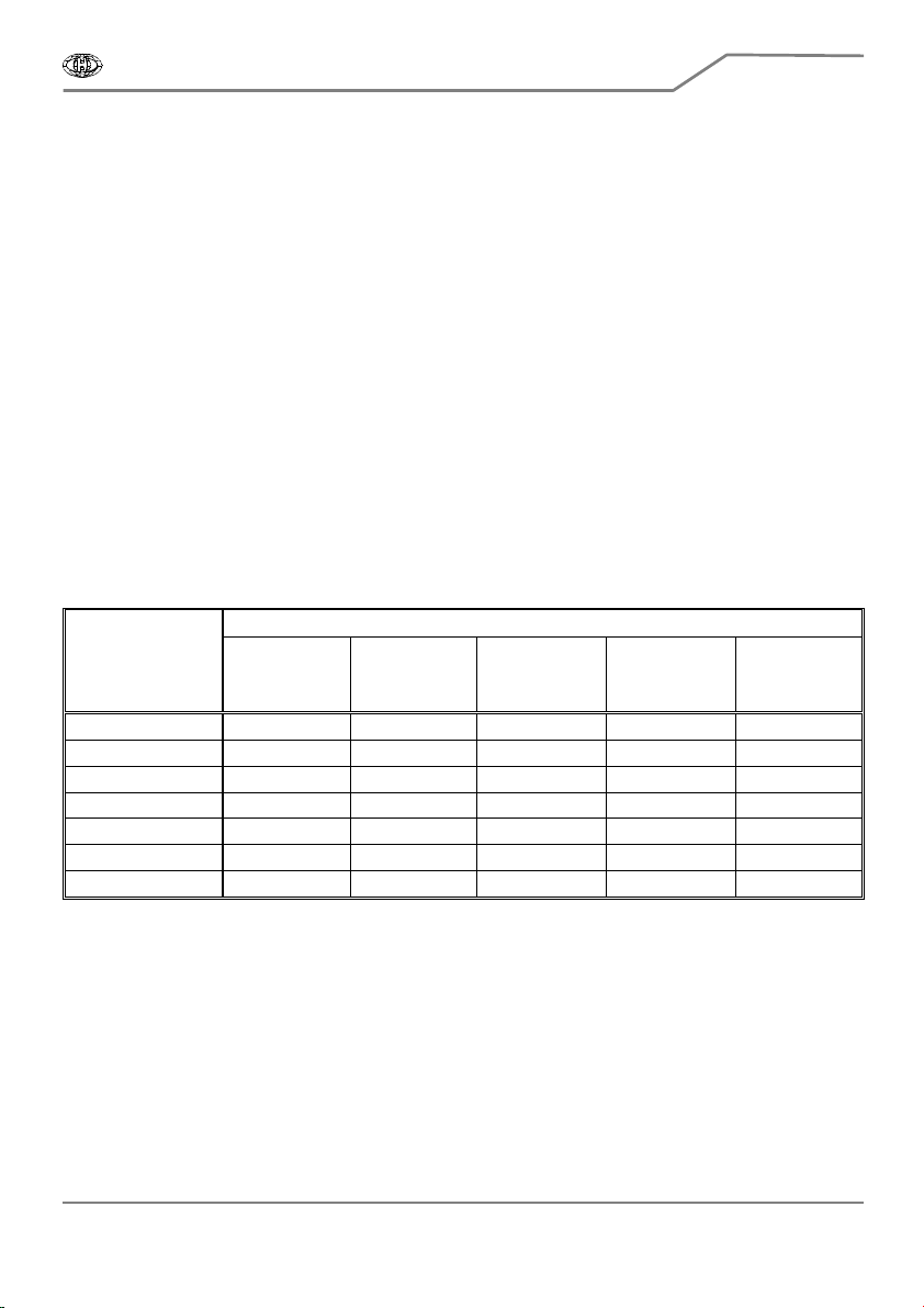
5. USER SETTING EXAMPLES
The table bellow shows the examples of approximate knob settings for typical effects. The
examples do not include external control of the module (inputs EXT-CV [2] and EXT-MOD [5] are not
used here).
Knob settings
Effect Manual (Dly)
0% = Long
100% = Short
Mix
0% = Dry
100% = Wet
Feedback
0% = Min
100% = Max
Int Mod Rate
0% = Slow
100% = Fast
Mod Depth
0% = Min
100% = Max
Chorus 0% ~ 50% 50% 0% 50% ~ 100% 50% ~ 100%
Phaser 100% 25% ~ 75% 25% ~ 60% 25% ~ 75% 25% ~ 100%
Flanger 50% ~ 100% 25% ~ 100% 25% ~ 60% 40% ~ 60% 25% ~ 100%
Jet Flanger 0% ~ 90% 25% ~ 100% 80% ~ 100% 40% ~ 60% 75% ~ 100%
Vibrato 25% ~ 100% 100% 0% 75% ~ 100% 50% ~ 100%
Dry Hall 0% 50% 25% ~ 60% Not relevant 0%
Chorus – Vibrato 0% ~ 25% 100% 50% ~ 75% 75% ~ 100% 75%

Stereo Bucket Brigade FX Unit
Module 7-702 v. 1. 0
Copyright © 2014 CHD Elektroservis. All rights reserved.
No part of this publication may be reproduced in any form without the written permission of CHD Elektroservis.
7
6. TECHNICAL PARAMETERS
Mechanical dimensions
Module width : 12 HU (60,5 mm)
Module height : 3 U (128,5 mm)
Module site depth : 64 mm (without power supply cable)
Power supply
Supply voltage : ±12 V from the system bus
Current requirement : max +55 mA / +12 V
max -25 mA / -12 V
Inputs / outputs
Inputs: AUDIO-IN min ±2,5 V
PP
for full driving / Z
IN
= 10 kΩ
EXT-CV 0 to +8 V for full driving / Z
IN
= 10 kΩ
EXT-MOD min ±2,5 V
PP
for full driving / Z
IN
= 10 kΩ
Outputs : OUTPUT-LEFT ±2,5 V
PP
/ Z
OUT
= 200 Ω (conforms to standard level +4 dB)
OUTPUT-RIGHT ±2,5 V
PP
/ Z
OUT
= 200 Ω (conforms to standard level +4 dB)
Accessory
Ribbon power supply cable with 10 / 16 pin connectors, length ca 200 mm
7. WARRANTY CONDITIONS
The equipment is provided with thirty-month warranty starting from the date of the equipment
take-over by the customer. This date must be specified on warranty list together with dealer's
confirmation. During this period of time, all defects of equipment or its accessories, caused by
defective material or faulty manufacturing, will be removed free of charge. Warranty repair is
asserted by the customer against the dealer. Warranty period is to be extended for the time period,
during which the product was under the warranty repair. The relevant legal regulations take effect
in case of cancellation of purchase contract.
The customer will lose the right for free warranty repair, if he will not be able to submit properly
filled out warranty list or if the defects of the product had been caused by:
• unavoidable event (natural disaster),
• connecting the device to the incorrect supply voltage,
• inputs or outputs overloading by connecting the signals source or load source with not-
corresponding characteristics etc.,
• faulty equipment operation, which is at variance with the instructions referred-to in the operating
manual,
• mechanical damage caused by consumer during transportation or usage of equipment,
• unprofessional interference with the equipment or by equipment modification without
manufacturer’s approval.

7
Table of contents
Other CHD Recording Equipment manuals

Popular Recording Equipment manuals by other brands


USB-Nachruesten
USB-Nachruesten MMI 2G Installation guide and user's manual

Behringer
Behringer B-Control Fader BCF2000 quick start guide

Juzisound
Juzisound Total SOLO Sampler MICRO quick start guide

Ramtech
Ramtech WES3 manual

Ovation Systems
Ovation Systems SoundByte user guide

Tascam
Tascam DV-RA1000 owner's manual

Fishman
Fishman FLUENCE KEITH MERROW installation guide

Dynex
Dynex DX-CVS4 Guide de l'utilisateur

Dantel
Dantel 00331 Installation & operation manual

Minebea
Minebea CC-Link CSD-709-73 instruction manual

Ocean Beach Digital
Ocean Beach Digital DB-1 user manual

OHAUS
OHAUS Ranger 4000 Count Series instruction manual