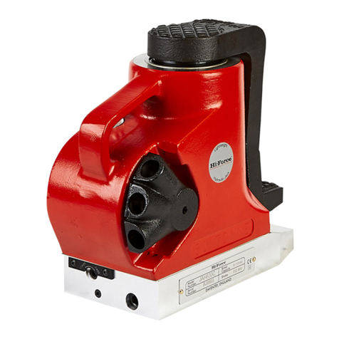
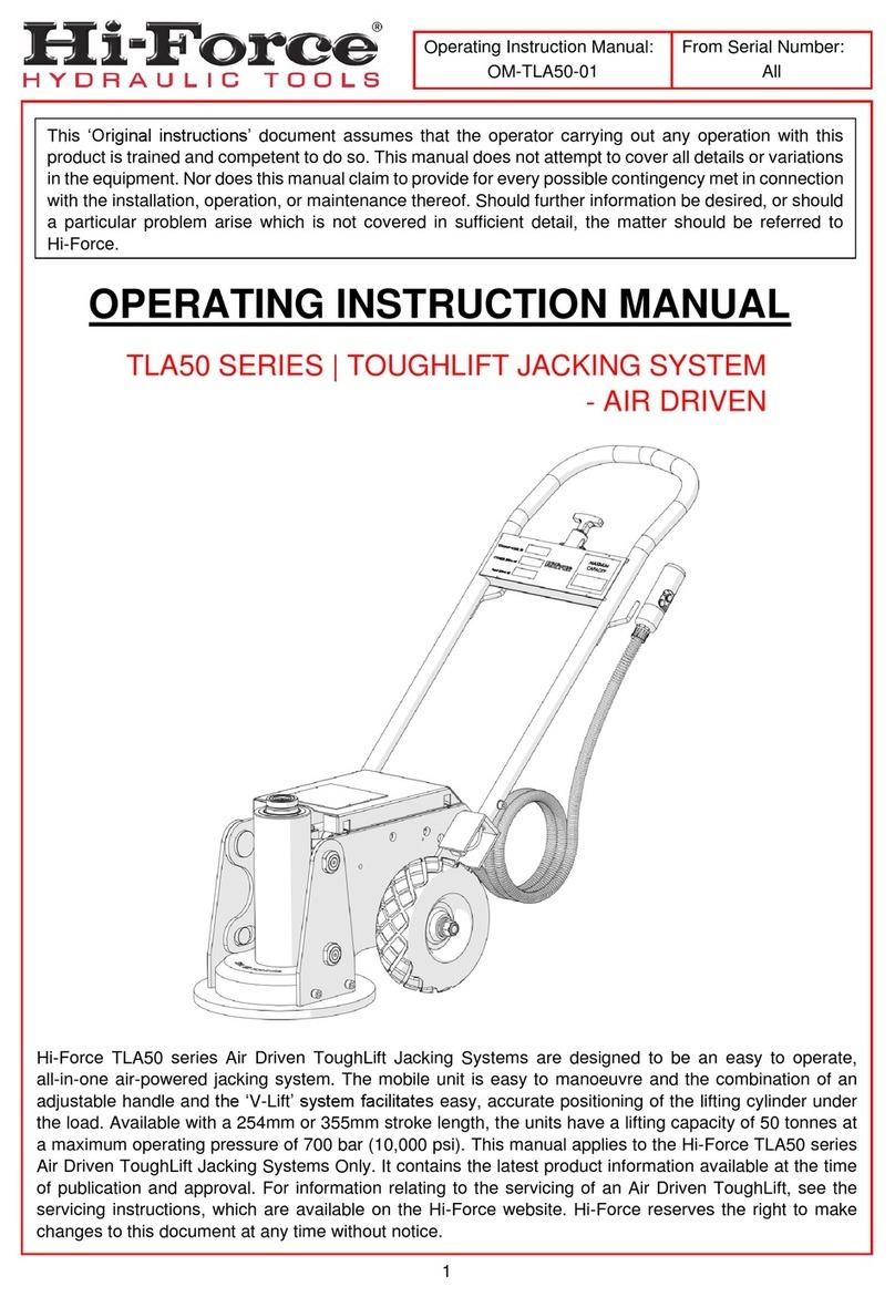
Hi-Force TLE50 Series Instruction Manual

Operating Instruction Manual:
OM-TLE50-01
From Serial Number:
All
1
OPERATING INSTRUCTION MANUAL
TLE50 SERIES | TOUGHLIFT JACKING SYSTEM
- ELECTRIC DRIVEN
Hi-Force TLE50 series Electric Driven ToughLift Jacking Systems are designed to be an easy to operate,
all-in-one electric-powered jacking system. The mobile unit is easy to manoeuvre and the combination of
an adjustable handle and the ‘V-Lift’ system facilitates easy, accurate positioning of the lifting cylinder under
the load. Available with a 254mm or 355mm stroke length, the units have a lifting capacity of 50 tonnes at
a maximum operating pressure of 700 bar (10,000 psi). This manual applies to the Hi-Force TLE50 series
Electric Driven ToughLift Jacking Systems Only. It contains the latest product information available at the
time of publication and approval. For information relating to the servicing of an Electric Driven ToughLift,
see the servicing instructions, which are available on the Hi-Force website. Hi-Force reserves the right to
make changes to this document at any time without notice.
This ‘Original instructions’ document assumes that the operator carrying out any operation with this
product is trained and competent to do so. This manual does not attempt to cover all details or variations
in the equipment. Nor does this manual claim toprovide for every possible contingency met in connection
with the installation, operation, or maintenance thereof. Should further information be desired, or should
a particular problem arise which is not covered in sufficient detail, the matter should be referred to
Hi-Force.

Operating Instruction Manual:
OM-TLE50-01
From Serial Number:
All
2
Table of Contents
1.0
Inspection upon Receipt..................................................................3
2.0
Safety Precautions...........................................................................3
3.0
Declaration of Incorporation/Conformity.......................................6
4.0
Component Identification ................................................................7
5.0
Installation/ Setup...........................................................................10
6.0
Operation ........................................................................................12
7.0
Lifting and Transport.....................................................................13
8.0
Maintenance and Storage..............................................................14
9.0
Specifications.................................................................................15
10.0
System Components/Accessories.............................................15
11.0
Troubleshooting...........................................................................16
12.0
Contact Details............................................................................. 18
NOTE: Images contained within this document are for illustrative purposes ONLY.

Operating Instruction Manual:
OM-TLE50-01
From Serial Number:
All
3
1.0
Inspection upon Receipt
Upon receipt of the product, visually inspect the item for any evidence of shipping damage. Please note:
the warranty does not cover shipping damage. Notify the courier immediately if shipping damage is found
and refrain from putting the product into service. The carrier is responsible for repair and replacement costs
resulting from damage that occurred in transit.
2.0
Safety Precautions
2.1
Introduction
Read and follow all the instructions and safety warnings carefully before handling, installation or
use of any hydraulic equipment. Failure to do so could lead to equipment damage, equipment
failure, personal injury or even death. Hi-Force will not be held responsible for any damage to the
equipment, injury or death resulting from the unsafe use of, lack of maintenance to, or incorrect operation
of the product. If in doubt on the correct use of anyHi-Force equipment, contact your nearest Hi-Forceoffice
or distributor. Only qualified personnel should be allowed to operate hydraulic equipment. If an operator has
not been trained on high-pressure hydraulic equipment and its safe usage, consult your local Hi-Force sales
office or distributor who can offer training courses for operators.
2.2
Work Area Safety
•
Keep work areas clean and well lit. Cluttered spaces and inadequate lighting can result in
unnecessary accidents.
•
Keep bystanders clear of any hydraulic tool activity. Personnel working in close-range should be
made aware of all high-pressure work before commencing.
•
Ensure that the lifting device/s are placed entirely under the load and that lifting is parallel.
2.3
Electrical Safety
•
Electrical power plugs/socketsMUST matchthepower source outlet socket. Never modify electrical
power plugs or tool/ equipment electrics.
•
DO NOT abuse cabling. DO NOT use electric cables to carry, move or disconnect tools. Make sure
electrical cabling is clear of heat sources, sharp edges or moving parts.
•
When using the unit outdoors, use a suitably rated extension lead (if required) to reduce the risk of
electric shock.

Operating Instruction Manual:
OM-TLE50-01
From Serial Number:
All
4
2.4
General Hydraulic System Safety Precautions
Failure to observe and obey the following safety precautions could result
in property damage, significant personal injury or death;
•
When operating any hydraulic equipment, all operators should ensure that all necessary personal
protective equipment (PPE) is worn, as specified by their employer. Steel toe-cap safety shoes,
safety glasses/ visor, andprotective gloves shouldbe worn at all times. All relevant risk assessments
should be completed before the use of the equipment.
•
Keep hydraulic equipment away from open flames and direct heat.
•
NEVER handle a pressurised hydraulic hose. Hydraulic fluid escaping under pressure from a
ruptured hose can penetrate the skin and lead to a significant medical emergency, and in some
cases, death. Should this incident occur, seek out medical attention immediately.
•
Seek medical attention immediately if a hydraulic injection injury (no matter how minor) occurs.
•
The system operating pressure MUST NOT exceed the pressure rating of the lowest-rated
component in the system.
•
Only use hydraulic tools/ cylinders in a complete and tested, coupled system. NEVER attempt to
use a tool/ cylinder that is not correctly coupled to its operational pump. NEVER pressurise
uncoupled couplers.
•
NEVER attempt to disconnect a hose from a hydraulic system until the system’s pressure has been
completely released. Doing so can result in that pressure becoming trapped within the system and
relieving trapped pressure can be dangerous.
•
Loosening a hydraulic fitting under pressure can result in the escape of hydraulic fluid at high
pressure, which can penetrate the skin and cause significant injury or death.
•
NEVER attempt to solve, or clean-up leaks in the system while the system is pressurised.
•
Immediately replace any worn or damaged parts using genuine Hi-Force parts only.
•
DO NOT use any hydraulic equipment if you are under the influence of alcohol, drugs or medication.
Lack of attention whilst operating high-pressure hydraulic tools can result in personal injury or death.

Operating Instruction Manual:
OM-TLE50-01
From Serial Number:
All
5
Failure to observe and obey the following safety precautions could result
in property damage, equipment damage or minor/ moderate personal
injury;
•
NEVER lift, carry or move any hydraulic components by the hose or hoses connected to them.
•
Avoid damaging hydraulic hoses. ALWAYS route hoses to ensure that they are free from sharp
bends and kinks. Using a sharply bent or kinked hose will result in severe back-pressure, which can
lead to hose failure.
•
NEVER use a coupler/s to lift, carry or position a tool.
•
Servicing of hydraulic equipment must only be undertaken by a qualified technician.
•
DO NOT drop or place heavy objects on a hydraulic hose, as this may cause
internal damage, which could result in rupture of the pressurised hose. A
ruptured hose could cause significant damage to components and possible
severe injury to personal operating nearby.
•
DO NOT let familiarity gained with any hydraulic tools allow you to become complacent.
Complacency with any tooling can result in a lack of discipline toward working guidelines and safety
principles.
•
DO NOT remove any labels from the product. Replace any damaged or unreadable labels
immediately.
•
Avoid loose clothing and jewellery that could get caught in moving parts, tie back long hair.
2.5
ToughLift Specific Safety Precautions
Failure to observe and obey the following safety precautions could result
in property damage, serious personal injury or death;
•
DO NOT work under or near a load supported only by hydraulic means. A hydraulic cylinder/ jack,
when used as a lifting device, should not be used as a load-holding device. Once lifted, all loads
should be supported using rigid mechanical structures.
•
ALWAYS place the unit on a flat, even surface that can support the load to be applied.
Where applicable, use an additional cylinder support base to assist in supporting the load to be
lifted.

Operating Instruction Manual:
OM-TLE50-01
From Serial Number:
All
6
•
NEVER exceed the maximum rated pressure or load capacity of any hydraulic cylinder. Hi-Force
manufactures its hydraulic cylinders to operate at a maximum working pressure of 700 bar (10,000
psi). DO NOT connect a pump with a higher pressure capacity rating to any Hi-Force cylinder of this
model series.
•
DO NOT adjust or remove the external pressure relief valve on any Hi-Force product.
•
Avoid lifting loads that are not central to the lifting piston. Avoid offset loading as this can damage
the cylinder bores and piston rods, and also lead to unstable load lifting.
•
NEVER invert the unit or lay it on its side, either in use, in transport or in storage.
•
DO NOT weld any items to the ToughLift unit or modify it in any way from its delivered condition.
Your warranty may be invalidated, and it could lead to serious personal injury.
•
ALWAYS use friction material under the base plate of the unit and between the jack and the load.
•
ONLY lift dead-weight (static) loads. DO NOT lift dynamic loads. i.e. Loads with a shifting centre of
mass.
•
NEVER exceed the maximum rated capacity of any hydraulic equipment. See Section 9.
•
Only use hydraulic cylinders in a complete and tested, coupled system. NEVER attempt to use a
cylinder that is not correctly coupled to its operational pump.
•
Overloading hydraulic cylinders can result in component failure and possible serious personal injury.
•
Keep hands and feet away from the cylinder during operation.
Failure to observe and obey the following safety precautions could result
in property damage, equipment damage or minor/moderate personal
injury;
•
To protect your warranty, only use the hydraulic oil grade specified in Section 5.2.
•
When moving the unit, make sure all power source and control pendant cables are kept clear of the
wheels, to avoid possible damage or entanglement of the cables.
3.0
Declaration of Incorporation/Conformity
Hi-Force declares that this product has been tested and complies with the standards set out in the relevant
EU directives. The EU Declaration of Incorporation / Conformity is included as Annex A to this instruction
document and is supplied with all shipments of this product.

Operating Instruction Manual:
OM-TLE50-01
From Serial Number:
All
7
4.0
Component Identification
1
Base Plate
5
Tilting Saddle
2
‘V-Lift’ System
6
Handle Release
3
Cylinder
7
Handle
4
Piston
8
Control Pendant
Figure 4.1: Component Identification

Operating Instruction Manual:
OM-TLE50-01
From Serial Number:
All
8
9
Power ‘ON/ OFF’ Switch
12
Top Cover
10
Electrical Control Box
13
Mains Power Plug
11
Electric Motor
14
Oil Drain Plug
Figure 4.2: Component Identification

Operating Instruction Manual:
OM-TLE50-01
From Serial Number:
All
9
15
Oil Reservoir
18
Handle Position Latch-Pin Holes
16
Oil Level Gauge
19
Oil Filler Breather Cap
17
Top Cover Mounting Cap Screws
20
Cylinder Overload Protection Valve
Figure 4.3: Component Identification

Operating Instruction Manual:
OM-TLE50-01
From Serial Number:
All
10
5.0
Installation/ Setup
5.1
Before First Use / Preparation
1. Immediately after unpacking, examine the unit for signs of transit damage and if found contact the
shipping company.
2. Establish the oil level in the oil reservoir (15) using the oil level gauge (16). Depending on the
shipping method used, the reservoir may either be supplied full or empty. If the reservoir is empty,
it must be correctly filled before use (See section 5.2). If the reservoir was supplied full of oil, no
further action is required.
IMPORTANT: Running the pump without oil will result in damage.
5.2
Filling the Reservoir with Oil
IMPORTANT: The TLE50 Range uses ISO46 Grade Hydraulic Oil.
•
Stand the ToughLift on a firm, level surface.
•
Open the Top Cover (12), by removing the 6 Cap Screws (17) holding the cover in place. (Seefigure
4.3 Item 17 for screw locations)
•
Remove the filler cap (19) from the filler breather.
•
Fill the reservoir with clean, high-quality ISO46 hydraulic oil via the filler breather until the oil level
reaches the centre of the upper oil level gauge sight-glass (16).
•
Replace the filler cap (19) on the filler breather.
•
Replace the Top Cover (12) and 6 Cap Screws (17). DO NOT operate the ToughLift without the Top
Cover securely in place.
Ensure the oil level does not fall below the minimum level. Running the pump without oil
will result in damage.
IMPORTANT: Only add oil to the reservoir when the lifting cylinder is fully retracted. Failure to do so will
result in the system containing more oil than the reservoir can hold.
5.3
Priming the Pump / Bleeding Trapped Air from the System
If the unit is delivered without oil or if air becomes trapped in the system, it will need to be primed/bled.
To do this, fully advance and retract the cylinder (unloaded) several times until operation is smooth.

Operating Instruction Manual:
OM-TLE50-01
From Serial Number:
All
11
5.4
Moving & Positioning the ToughLift
1. Adjust the handle into the most comfortable position by [1] pulling up on the handle release (6) and
[2] rotating the handle (7) to the desired position. [3] Let go of the handle release (6) and allow the
locating pins to engage the handle latch-pin holes (18) on the side of the ToughLift main housing
(See figure 5.1).
2. Use the handle (7) to tilt the jack right back onto its wheels, allowing it to be manoeuvred to its
required location (See figure 5.2).
3. Position the jack accurately under the lifting point by adjusting the handle to its lowest position and
tilting the jack back slightly onto its wheels (See figure 5.3).
This allows the jack to be moved while the ‘V-Lift’ system keeps the cylinder vertical.
Make sure that when the base plate is lowered to the floor and the handle is
allowed to rise back up, your hands are clear of any pinch points above.
4. Make sure the cylinder saddle (5) is central to the lifting point before the lift is started.
ALWAYS make sure the jack is positioned directly under the load and lifts vertically.
Figure 5.1: Handle Adjustment
Figure 5.2: Moving the Unit Figure 5.3: Accurate Positioning of the Unit

Operating Instruction Manual:
OM-TLE50-01
From Serial Number:
All
12
6.0
Operation
1. Connect the ToughLift unit to the available power source.
2. Turn the motor on by pressing the green ‘ON’ button (9) on the electrical control box (10).
3. Using the remote ‘control pendant’ (8), press the ‘UP’ button to extend/advance the jacking cylinder
and the ‘DOWN’ button to retract /lower the jacking cylinder. (See figure 6.1)
4. Advance the jacking cylinder to lift the load. Check constantly to make sure the load is stable and
that the jack remains in a fixed and stable, ‘vertical’ position.
5. Fit load blocks as required and lower the load onto the load blocks (if used).
6. Retract the jacking cylinder to lower the load. Check constantly to make sure the load is stable and
that the jack remains in a fixed and stable, ‘vertical’ position.
7. Turn the motor off by pressing the red ‘OFF’ button (9) on the electrical control box (10).
Figure 6.1: Control Pendant Operation

Operating Instruction Manual:
OM-TLE50-01
From Serial Number:
All
13
7.0
Lifting and Transport
7.1 Lifting the Toughlift
•
Before lifting the unit, adjust the handle (See figure 5.1) into its forward most locked position (See
figure 7.1). This places the handle directly over the units’ centre of gravity, allowing it to be safely
lifted by its handle.
•
Attach the lifting strap to the uppermost horizontal beam of the handle assembly (See figure 7.2).
IMPORTANT: A lifting strap with a minimum capacity of 1 tonne and appropriately rated shackles
fitted to each end, must be used.
•
If necessary, attach guide wires to help control the movement of the unit during the lift.
•
The ToughLift unit can now be safely lifted.
Figure 7.1: Handle Position for Lifting the Unit Figure 7.2: Lifting the Unit
7.2 Transporting the Toughlift
•
Make sure the unit is securely fastened down and cannot shift during transport.

Operating Instruction Manual:
OM-TLE50-01
From Serial Number:
All
14
8.0
Maintenance and Storage
Carry out basic maintenance on a regular basis to keep the jacking system operating in a trouble-free
manner. Maintenance intervals are determined by the frequency of use of the system and the operating
conditions on site.
•
Keep the unit clean. Particularly the saddle and load-lock/slip-lock extension pieces (if used).
All saddle receiver holes should be blown out with compressed air. Then lightly lubricate the saddle
pins and saddle receiver holes. Lubricate the handle positioning latch pins and holes (18).
•
The oil level in the reservoir should not be allowed to drop below the centre of the top oil level
indicator sight-glass (16). (Cylinder fully retracted)
•
ALWAYS check the oil level with the lifting cylinder in the fully retracted position toensure the correct
oil level is displayed. Keep the oil reservoir topped-up with high grade ISO46 hydraulic oil as per
section 5.2.
If the oil level does fall below the lower oil level indicator (at any time), air could
be drawn into the pump, causing erratic operation and possible damage. To top
up hydraulic oil, remove the top cover (12) and fill via the orange filler breather
cap (19). (See Section 5.2).
Oil should be replaced after approximately 500 working hours, or more frequently in dusty
conditions. To replace the oil, disconnect from the mains power supply, remove the oil drain plug
(14) on the bottom of the reservoir and drain the used oil into a suitable container. Replace the oil
drain plug (14) and refill with high grade ISO46 hydraulic oil as per section 5.2. Bleed trapped air
from the system if necessary (See section 5.3).
IMPORTANT: ALWAYS dispose of used hydraulic oil in a responsible manner, in accordance with
local regulations.

Operating Instruction Manual:
OM-TLE50-01
From Serial Number:
All
15
9.0
Specifications
Refer to the nameplate on the unit for model identification.
TLE50 | ToughLift Jacking System –Electric Driven
Model Number
Capacity
(tonnes)
Power Supply
Stroke
(mm)
Weight
(kg)
Max
Additional
Stack
(mm)
TLE5010
50
240V - Electric
254
160
680
TLE5014
50
240V - Electric
355
170
680
ToughLift TLE50 Systems use a 2-stage pump with the following pressure ranges and flow rates
Pump Stage
Pressure Range
(bar)
Flow
(l/ min)
1
0 - 60
3.9
2
60 - 700
0.36
10.0
System Components/Accessories
(Refer to the Hi-Force website or latest Hi-Force catalogue, for further details)
•
Range of Slip Lock Extensions (180mm –500mm)
•
Range of Load Lock Extensions (180mm –500mm)
•
Trolley Mounted Load Block Set

Operating Instruction Manual:
OM-TLE50-01
From Serial Number:
All
16
11.0
Troubleshooting
Hi-Force TLE50 ToughLift Jacking Systems should be serviced and repaired only by authorised Hi-Force
repair centres. The following table gives possible causes and solutions for common problems.
TROUBLESHOOTING GUIDE
Problem
Possible Cause
Solution
1. Pump will not start.
a. Power supply not connected.
Connect power supply.
b. Damaged power cord.
Repair or replace the power cord.
c. Circuit breaker tripped.
i.
Reset Circuit breaker.
ii.
Ensure breaker is adequately rated.
d. Blown fuse.
Replace blown fuse.
e. Motor is damaged, seized or worn.
Contact your local Hi-Force office/distributor.
2. Motor stalls before full
operating pressure is
reached.
a. Low supply voltage.
i.
Use heavier gauge extension cord.
ii.
Turn off excess electrical loads.
3. Pump struggles to
build pressure or
maintain pressure
under load.
a. Oil level too low
Check unit for visible leaks. Add oil as per
section 5.2.
b. External oil leak in the system.
Contact your local Hi-Force office/distributor.
4. Pump running hot.
a. Low oil level.
Add oil as per section 5.2.
b. High-Pressure leakage at pump.
Contact your local Hi-Force office/distributor.
5. Cylinder will not
advance.
a. Pump malfunction.
Contact your local Hi-Force office/distributor.
b. Oil level too low.
Add oil as per section 5.2.
c. Load too heavy for the cylinder.
Make sure the weight of the load to be lifted is
within the rated capacity of the unit.
d. Cylinder seals leaking.
Contact your local Hi-Force office/distributor.
e. Faulty control pendant.
Contact your local Hi-Force office/distributor.
6. Cylinder advances part
way.
a. Oil level too low.
Add oil as per section 5.2.
b. Cylinder piston binding.
Contact your local Hi-Force office/distributor.
c. External obstruction.
Retract cylinder and clear obstruction.

Operating Instruction Manual:
OM-TLE50-01
From Serial Number:
All
17
TROUBLESHOOTING GUIDE (continued…)
Problem
Possible Cause
Solution
7.Erratic cylinder
movement.
a. Leakage from pump or valve
internal components.
Contact your local Hi-Force office/distributor.
b. Internal leak, due to damaged/worn
seals or valves.
Contact your local Hi-Force office/distributor.
c. Oil level too low.
Check unit for visible leaks. Add oil as per
section 5.2.
d. Air in the hydraulic system.
Bleed air from the system. (See section 5.3)
e. Cylinder piston binding.
Contact your local Hi-Force office/distributor.
f. Pump solenoid faulty.
Contact your local Hi-Force office/distributor.
8. Cylinder stalls under
load or before
maximum tonnage is
reached.
a. Control Valve damaged.
Contact your local Hi-Force office/distributor.
b. Seal damage/wear or internal
damage.
Contact your local Hi-Force office/distributor.
9. Cylinder advances, but
will not hold.
a. Pump malfunction.
Contact your local Hi-Force office/distributor.
b. Leaking connection.
Replace faulty component.
c. Cylinder seals leaking.
Contact your local Hi-Force office/distributor.
10. Cylinder leaks oil.
a. Worn or damaged seals.
Contact your local Hi-Force office/distributor.
b. Internal cylinder damage.
Contact your local Hi-Force office/distributor.
c. Loose connection.
Tighten or repair the connection.
11. Cylinder will not
retract or retracts
slower than normal.
a. Faulty control pendant.
Contact your local Hi-Force office/distributor.
b. Oil reservoir over-filled.
Drain excess oil from oil reservoir.
c. Internal cylinder damage.
Contact your local Hi-Force office/distributor.
d. Valve malfunction.
Contact your local Hi-Force office/distributor.
12. Overload protection
valve (20) leaking.
a. Faulty Valve.
Contact your local Hi-Force office/distributor.
13. Noisy Operation
a. Air trapped in the hydraulic system.
Bleed air from the system. (See section 5.3)
b. Air leaking into the hydraulic
system.
Visually inspect all areas where air might leak
into the hydraulic system.
c. Oil level too low.
Check unit for visible leaks. Add oil as per
section 5.2.

Operating Instruction Manual:
OM-TLE50-01
From Serial Number:
All
18
Head Office:
Hi-Force Limited
Prospect Way, Daventry, Northamptonshire
NN11 8PL
United Kingdom
Tel: + 44 1327 301000
Fax: + 44 1327 706555
www.hi-force.com
Regional Offices:
For more information on our offices worldwide, scan the below QR code.
This manual suits for next models
2
Table of contents
Other Hi-Force Jack manuals