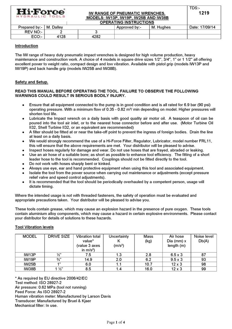
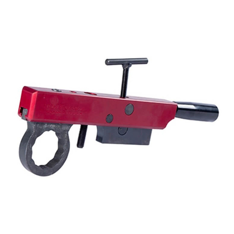
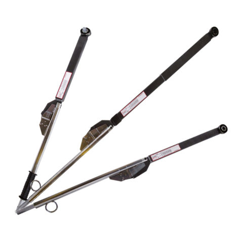
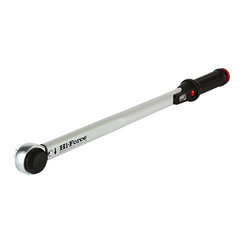
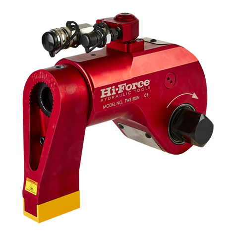
Hi-Force TWS-N Series User manual

TDS1288
Page 1 of 7
www.hi-force.com
OPERATION MANUAL
Hi-Force®TWS-N SERIES
SQUARE DRIVE HYDRAULIC TORQUE WRENCHES
NOTICE
Series TWS-N Series Square Drive Hydraulic Torque Wrenches are designed for installing and removing
threaded fasteners requiring precise high torque during bolt makeup and maximum torque during bolt
breakout.
0609
WARNING
IMPORTANT SAFETY INFORMATION ENCLOSED.
READ THIS MANUAL BEFORE OPERATING TOOL.
IT IS THE RESPONSIBILITY OF THE EMPLOYER TO PLACE THE INFORMATION IN THIS
MANUAL INTO THE HANDS OF THE OPERATOR.
FAILURE TO OBSERVE THE FOLLOWING WARNINGS COULD RESULT IN INJURY.
PLACING TOOL IN SERVICE
•Always operate, inspect and maintain this tool in accordance with International Standards ISO9001
and ANSI B30.1.
•This tool will function using an air or electric powered hydraulic pump. Adhere to the pump safety
requirements and follow instructions when connecting the pump to the tool.
•Use only equipment rated for the same pressure and torque.
•Use only a hydraulic pump capable of generating 10,000 psig (700 bar) maximum pressure with this
tool.
•Use only twin line hydraulic hose rated for 10,000 psig (700 bar) pressure with this tool.
•Do not interchange the male and female swivel inlets on the tool or the connections on one end of the
hose. Reversing the inlets will reverse the power stroke cycle and may damage the tool.
•Do not use damaged, frayed or deteriorated hoses and fittings. Make certain there are no cracks,
splits or leaks in the hoses.
•Use the quick connect system to attach the hoses to the tool and pump. Make certain the spring-loaded
retaining rings are fully engaged to prevent the connectors from disengaging under pressure.
•When connecting hoses that have not been preloaded with hydraulic oil, make certain the pump reservoir is not
drained of oil during start-up.
•Do not remove any labels. Replace any damaged label.
USING THE TOOL
•Do not handle pressurised hoses. Escaping oil under pressure can penetrate the skin, causing serious injury.
If oil is injected under the skin, see a doctor immediately.
•Never pressurise uncoupled couplers. Only use hydraulic equipment in a coupled system.
•Always wear eye protection when operating or performing maintenance on this tool.
•Always wear head and hand protection and protective clothing when operating this tool.
The use of other than genuine Hi-Force replacement parts may result in safety hazards, decreased tool
performance, and increased maintenance, and may invalidate all warranties.
NOTICE
Repairs should be made only by authorised personnel. Consult your nearest Hi-Force Authorised
Service centre.
Refer All Communications to the Nearest Hi-Force Office or Distributor.

TDS1288
WARNING
FAILURE TO OBSERVE THE FOLLOWING WARNINGS COULD RESULT IN INJURY
USING THE TOOL
•Keep hands, loose clothing and long hair away from the reaction arm and working area during
operation. Do not attempt to support the tool with your hands during operation.
•This tool will exert a strong reaction force. Use proper mechanical support and correct reaction arm
positioning to control these forces. Do not position the reaction arm so that it tilts the tool off the axis
of the bolt and never use the swivel inlets as a reaction stop.
•Avoid sharp bends and kinks that will cause severe back-up pressure in hoses and lead to premature
hose failure.
•Use accessories recommended by Hi-Force.
•Use only impact sockets and accessories. Do not use hand (chrome) sockets or accessories.
•Use only sockets and accesssories that correctly fit the bolt or nut and function without tilting the
tool off the axis of the bolt.
•This tool is not designed for working in explosive atmospheres
•This tool is not insulated against electric shock. When using this tool with a pump having an electrical
power source or circuits, follow the pump instructions for proper grounding.
Always wear eye protection when operating
or performing maintenance on this tool.
Always wear eye protection when operating
or performing maintenance on this tool.
Always turn off the pump and
disconnect the power before installing,
removing, or adjusting any accessory on
this tool, or before performing any
maintenance on this tool.
POWER
OFF ON
POWER
OFF ON
Always wear ear protection
when operating this tool.
Page 2 of 7
www.hi-force.com 0609
!
The Torque Reaction Arm must be positioned
against a positive stop. Do not use the Arm as a dead
handle. Take all precautions to make certain the
operator’s hand cannot be pinched between the Arm
and a solid object.
Operate at 10,000 psig (700
bar) maximum pressure.
10,000 psig
(681 bar)
10,000 psig
(700 bar)
Do not carry the tool by the
hose. Do not use damaged, frayed or
deteriorated hydraulic hoses and fittings.
Keep body stance balanced and firm. Do not
overreach when operating this tool.
PLACING THE TOOL IN SERVICE
CONNECTING THE TOOL
1. Attach the twin line hose to the uni-swivel coupling of the Square Drive Torque Wrench using the spring–
loaded quick connect ends. Make certain that they are fully engaged.
2. Connect the opposite ends of the hose to the Pump in the same manner.
ADJUSTMENTS
SETTING THE SQUARE DRIVE FOR
ROTATION
The position of the Square Drive when looking toward the Shroud will determine if the tool is set to tighten or
loosen the nut. When the Square Drive extends to the left when looking at the Shroud from the front, the tool is
set to loosen the nut. When the Square Drive extends to the right, the tool is set to tighten the nut. To change
the direction of rotation press the push button release on the drive retaining plate and pull the Square Drive out
of the Housing. Insert the Square Drive into the opposite side of the Housing and secure it by installing the push
button release retaining plate into the end of the drive.

TDS1288
SETTING THE TORQUE
After determining the desired torque, use the torque conversion chart on the Shroud or the torque conversion
charts on page 5 to determine the pressure that is necessary to achieve that torque.
1. Connect the tool to the power supply and turn the pump on.
2. Depress the advance remote control button causing the pressure to be shown on the gauge.
3. Adjust the pressure by first loosening the nut that locks the pressure adjustment handle and then rotate the
handle clockwise to increase the pressure and counter clockwise to decrease the pressure.
When decreasing pressure, always lower the pressure below the desired point and then bring the pressure
gauge back up to the desired pressure.
4.When the desired pressure is reached, retighten the lock nut and cycle the tool again to confirm that the
desired pressure setting has been obtained.
SETTING THE REACTION ARM
The function of a reaction device is to hold the tool in position against the forces generated to tighten or loosen
bolts or nuts. Hydraulic wrenches generate tremendous force.
WARNING
An improperly positioned reaction arm may
result in operator injury or damaged tooling.
Make sure the Reaction Arm is positioned correctly. (Refer to Drawing 01).
The Reaction Arm can be positioned in numerous places within a 360O circle. However, for the Arm to be
correctly positioned, it must be set within a 90Oquadrant of that circle. That quadrant is the area located
between the protruding Square Drive and the bottom of the Housing away from the Swivel Inlets. It will always
be toward the lower half of the Housing and on one side of the Housing when tightening and the other side
when loosening.
OPERATING THE WRENCH
The position of the Square Drive relative to the Shroud determines whether the action will tighten or loosen the
nut. (Refer to Dwg. 02 for application examples).
The power stroke of the Piston Assembly will always turn the Square Drive toward the Shroud.
WRENCH POSITIONS
1. Place the Square Drive in the socket, insert the socket retainer ring and pin, and place the socket on the nut.
Make certain the Square Drive and socket are the correct size for the nut and that the socket fully engages the
nut
2. Position the reaction arm against an adjacent nut, flange or solid system component. Make certain that there
is clearance for the hoses and uni-swivel coupling. DO NOT allow the tool to react against the hoses, or uni-
swivel coupling. When reacting directly off the tool body ie., with reaction arm removed DO NOT react off the
exposed End Plug Spigot.
3. After having turned the Pump on and presetting the pressure for the correct torque, depress the remote
control advance button to advance the Piston Assembly
4. When the wrench is started, the reaction surface of the wrench or Reaction Arm will move against the contact
point and the nut will begin to turn. Once the piston reaches the end of its stroke depress the remote control
return button to retract the piston.
5. Continue this cycling operation of advance
and retract until the nut is no longer turning and the Pump Gauge reaches the preset pressure. The piston rod
will retract when the retract button is pressed and under normal conditions, an audible “click” will be heard as
the tool resets itself.
6. Continue to cycle the tool until it “stalls” and the preset psi/torque has been attained.
7. Once the nut stops rotating, cycle the tool one last time to achieve total torque.
Page 3 of 7
www.hi-force.com 0609

TDS1288
Square Drive Position for Loosening and Tightening
(Dwg. 02)
Square Drive Hydraulic Wrench
Reaction Points (Dwg. 01)
Page 4 of 7
www.hi-force.com 0609

TDS1288
Page 5 of 7
www.hi-force.com 0609
PLACING THE TOOL IN SERVICE
LUBRICATION
Marine Grade Moly Lube
Lubrication frequency is dependent on factors known only to the user. The amount of contaminants in the work
area is one factor. Tools used in a clean room environment will obviously require less service than a tool used
out-doors and dropped in loose dirt or sand. Marine Grade Moly Lube is formulated not to wash out of the tool in
areas where lubrication is critical.
Whenever lubrication is required, lubricate as follows:
1. Remove the Drive Plate, Ratchet, Segment Pawl and Drive Sleeves and wash the components in a suitable
cleaning solution in a well–ventilated area.
2. After drying the components, wipe a film of Moly Lube (Marine Grade) onto the wear surface of both Drive
Sleeves and the ends of the Ratchet.
3. Spread a light film of Moly Lube (Marine Grade) onto the inner face and both sides of the Drive Plate.
Do not pack the teeth of the Segment Pawl or Ratchet with lube. It can prevent the teeth from engaging
properly.

TDS1288
Page 6 of 7
www.hi-force.com 0609
TWS-N SERIES TORQUE CONVERSION CHART
PSI / lbf.ft BAR / Nm
TWS17N TWS45N TWS100N
TWS150N
TWS370N
TWS17N
TWS45N
TWS100N
TWS150N
TWS370N
PSI lbf.ft lbf.ft lbf.ft lbf.ft lbf.ft BAR
Nm Nm Nm Nm Nm
1000 125 332 738 1,106 2,729 100
246 652 1,449 2,174 5,362
1500 188 498 1,106 1,659 4,094 150
370 978 2,174 3,261 8,043
2000 251 664 1,475 2,213 5,458 200
493 1,304 2,899 4,348 10,725
2500 314 830 1,844 2,766 6,823 250
616 1,630 3,623 5,435 13,406
3000 376 996 2,213 3,319 8,187 300
739 1,957 4,348 6,522 16,087
3500 439 1,162 2,581 3,872 9,552 350
862 2,283 5,072 7,609 18,768
4000 502 1,328 2,950 4,425 10,916 400
986 2,609 5,797 8,696 21,449
4500 564 1,494 3,319 4,978 12,281 450
1,109 2,935 6,522 9,783 24,130
5000 627 1,660 3,688 5,532 13,645 500
1,232 3,261 7,246 10,870 26,812
5500 690 1,826 4,056 6,085 15,010 550
1,355 3,587 7,971 11,957 29,493
6000 752 1,992 4,425 6,638 16,374 600
1,478 3,913 8,696 13,043 32,174
6500 815 2,158 4,794 7,191 17,739 650
1,601 4,239 9,420 14,130 34,855
7000 878 2,324 5,163 7,744 19,103 690
1,700 4,500 10,000 15,000 37,000
7500 941 2,490 5,531 8,297 20,468
8000 1,003 2,656 5,900 8,850 21,832
8500 1,066 2,822 6,269 9,404 23,197
9000 1,129 2,988 6,638 9,957 24,561
9500 1,191 3,154 7,006 10,510 25,926
10,000 1,254 3,320 7,375 11,063 27,290

TDS1288
Troubleshooting Guide
Trouble Probable Cause Solution
Couplers are not securely
attached to the tool or pump
Check the Coupler connections
and make certain that they are
connected.
Coupler is defective Replace any defective Coupler.
Defective remote control unit Replace the button and/or control
pendent
Piston will not advance or
retract
Dirt in the direction-control
valve of the pump unit Disassemble the pump and clean
the direction-control valve.
Hose connections reversed
Make certain the advance on the
pump is connected to the advance
on the tool and retract on the
pump is connected to the retract
on the tool.
Retract hose not connected Connect the retract hose securely
Piston will not retract
Retract pin broken Replace the broken pin and/or
spring
Piston Seal and/or End Plug
Seal leaking Replace any defective O-rings
Cylinder will not build up
pressure Coupler is defective Replace any defective Coupler
Grease or dirt build up in the
teeth of the Ratchet and
Segment Pawl
Disassemble the Ratchet and
clean the grease or dirt out of the
teeth
Square Drive will not turn Worn or broken teeth on
Ratchet an/or Segment Pawl Replace any worn or damaged
parts
Defective relief valve Inspect, adjust or replace the relief
valve
Air supply too low or air hose
too small
Make certain the air supply and
hose size comply with the pump
manual recommendations.
Electric power source is too
low
Make certain the amperage,
voltage and any extension cord
size comply with the pump manual
requirements
Defective Gauge Replace the Gauge
Low oil level Check and fill the pump reservoir
Pump will not build up
pressure
Clogged filter Inspect, clean and/or replace the
pump filter
Pressure reading erratic Defective Gauge Replace the Gauge
Nut Returns with retract
stroke Ball Plungers are not engaging
the Drive Sleeves Thread the Ball Plungers to the
correct depth in the Housing.
NOTICE
SAVE THESE INSTRUCTIONS. DO NOT DESTROY.
Page 7 of 7
www.hi-force.com 0609
Other manuals for TWS-N Series
1
This manual suits for next models
5
Table of contents
Other Hi-Force Power Tools manuals
Popular Power Tools manuals by other brands
BROWIN
BROWIN 810001 Instructions for use
Ingersoll-Rand
Ingersoll-Rand 1100PS4 Series Operation and maintenance manual

Hakko Electronics
Hakko Electronics FV-310 instruction manual
Aicon Air
Aicon Air DAC3050 Instructions for use
Sherline Products
Sherline Products 5000 series operating instructions

HIKOKI
HIKOKI M 12VE Handling instructions
