Hibon NX 2 Installation and operating instructions
80446693
Revision B
August 2013
Save These Instructions
NX Blowers
Installation, Operation and Maintenance
Installation, Operation and Maintenance
EN
Instalación, operación y mantenimiento
ES
Installation, fonctionnement et entretien
FR
Installation, Betrieb und Wartung
DE
Installazione, funzionamento e manutenzione
IT
Authorized Hibon Distributor, Service & Repair Facility
120 – 10293 276 ST, Acheson, Alberta, Canada T7X 6A5
T: 780.962.1827 F: 780.962.1830 E: sales@fraserwoods.ca
www.fraserwoods.ca

EN
EN-2 80446693 Rev. B
DECLARATION OF INCORPORATION
(as dened by the EU Machinery Directive 2006/42/EC Appendix II 1B)
DÉCLARATION D’INCORPORATION
(comme dénie par la directive européenne 2006/42/CE appendice II 1B relative aux machines)
WE, / NOUS,
INGERSOLL RAND AIR SOLUTIONS HIBON
Declare that, under our sole responsibility, the partly completed machinery:
Déclarons que, sous notre seule responsabilité, la presque-machine :
Description : Air Positive Displacement Blower Air End
Year of Manufacturing : 2013
Model Serial Number
NX 2 From 14151171 To 14159999
NX 3 From 14160901 To 14169999
NX 5 From 14170104 To 14179999
NX 8 From 15151260 To 15159999
NX 12 From 15170891 To 15179999
NX 18 From 16150103 To 16159999
NX 26 From 16170996 To 16179999
Has been designed, manufactured and tested in accordance with the requirements of directive 2006/42/EC and the relevant technical
documentation is compiled in accordance with annex VII B:
A été concue, fabriquée et testée en accord avec les exigences de la directive 2006/42/CE et que le dossier technique relatif a été
construit en accord avec l’annexe VII B:
This partly completed machinery must not be put in service until the nal machinery into which is to be incorporated has been
declared in conformity with the provisions of this directive
Cette presque-machine ne doit pas être mise en service tant que l’ensemble dans lequel elle doit être intégrée n’a pas été déclaré
conforme aux dispositions de la directive ci-dessus
The partly completed machinery to which this declaration relates is also in conformity with the following principal standards /
normative:
La Presque-machine à laquelle se réfère cette déclaration est également conforme aux principaux standards et normes suivants:
EN 1012-1 EN 1012-2 EN ISO 12100:2010
We undertake to transmit, in response to a reasoned request by national authorities, relevant information on the partly completed
machinery to which this declaration relates.
Nous nous engageons à transmettre, en réponse à une demande adéquatement motive des autorités nationales, les informations
appropriées concernant la Presque-machine à laquelle se réfère cette déclaration.
Wasquehal, 01st June 2013
Judicaël DE MEYERE
The signer of this Declaration of Incorporation is also the person authorized to compile the relevant technical documentation.
Le signataire de cette Déclaration d’Incorporation est aussi la personne autorisée à élaborer le dossier technique approprié.
www.fraserwoods.ca

80446693 Rev. B EN-3
EN
1. INTRODUCTION .................................... 4
1.1 Scope and denitions ...............................4
1.2 Description .........................................4
1.2.1 Introduction .......................................4
1.2.2 Principle of operation ..............................4
1.3 Applications ........................................4
2. TECHNICAL DATA................................... 6
2.1 Operating and storage conditions ...................6
2.2 Mechanical data ....................................6
2.3 Performance ........................................6
2.4 Noise and vibration data ............................8
2.5 Lubrication data ....................................9
2.6 Materials of construction ............................9
2.7 Item Numbers......................................10
2.8 Connections .......................................12
3. INSTALLATION .................................... 15
3.1 Installation safety ..................................15
3.2 System design and safety...........................15
3.2.1 General requirements .............................15
3.2.2 System safety .....................................15
3.3 Unpack and inspect ................................16
3.4 Prepare, locate and connect the blower.............16
3.4.1 Introduction ......................................16
3.4.2 Prepare, locate and connect blowers installed
directly in your system..................................16
3.4.3 Prepare, locate and connect a blower supported
by mounting feet.......................................17
3.5 Fill the blower with oil..............................17
3.6 Fit the drive/transmission...........................17
3.7 Check the direction of rotation .....................18
3.8 Commissioning the blower .........................18
•
•
•
•
•
•
•
4. OPERATION ....................................... 19
4.1 General operational safety..........................19
4.2 Start-up............................................19
4.3 Shut-down.........................................19
5. MAINTENANCE.................................... 20
5.1 Safety information .................................20
5.2 Maintenance plan..................................20
5.3 Check the oil levels.................................20
5.3.1 Inspect the oil-level sight-glasses ..................20
5.3.2 Drive Head Plate ..................................20
5.3.3 Non-drive Head Plate..............................21
5.4 Inspect the system installation......................21
5.5 Change the oil .....................................21
5.5.1 Drive Head Plate ..................................21
5.5.2 Non-drive Head Plate .............................21
5.6 Overhaul the blower ...............................21
5.7 Fault nding .......................................22
6. STORAGE AND DISPOSAL .......................... 24
6.1 Storage ............................................24
6.1.1 Preparation .......................................24
6.1.2 Long-term storage ................................24
6.2 Disposal ...........................................24
7. SERVICE AND SPARES.............................. 25
7.1 Introduction .......................................25
7.2 Service.............................................25
7.3 Spares and repair kits...............................25
RETURN OF Ingersoll Rand EQUIPMENT -
PROCEDURE......................................... 26
RETURN OF Ingersoll Rand EQUIPMENT -
DECLARATION....................................... 27
•
•
•
•
•
•
•
CONTENTS
www.fraserwoods.ca
EN
EN-4 80446693 Rev. B
1. INTRODUCTION
1.1 Scope and denitions
This manual provides installation, operation and maintenance
instructions for the Ingersoll Rand NX Blowers, which may be
abbreviated to“blowers” in the remainder of this manual. You
must use the blowers as specied in this manual.
Read this manual before you install and operate your blower.
Important safety information is highlighted as WARNING and
CAUTION instructions; you must obey these instructions. The
use of WARNINGS and CAUTIONS is dened below.
WARNING
Warnings are given where failure to observe the
instruction could result in injury or death to people.
Cautions are given where failure to observe the
instruction could result in damage to the equipment,
associated equipment and process.
The identication and rating plate (Figure 1, item 13) provides
specic details about the blower, such as its Item Number and
so on.
The following warning symbols may be tted to the blower or
associated equipment:
Warning – refer to accompanying
documentation.
Warning – hot surfaces.
Ear defenders must be worn.
The units used throughout this manual conform to the SI
international system of units of measurement.
Equivalent values in imperial units are also included.
1.2 Description
1.2.1 Introduction
Refer to Figure 1.The NX blowers are positive displacement
blowers, which incorporate two three-lobe rotors (8). One
of the rotors is driven by the drive shaft (5).The other rotor is
maintained in the correct phase relation by timing gears.The
timing gears and the bearings on the rotors and drive shaft
are lubricated by oil in the drive end cover (4) and non-drive
end cover (12).
The blowers are supplied in ‘bareshaft’ form. You must
connect your own coupling or belt drive system (see Section
3.6) to the drive shaft (5) in order to operate the blower.
The blowers are available in eight dierent positions
depending:
Flow direction
Shaft position
Direction of rotation
Refer to Section 2.7 and gure 2 for the Item Numbers of the
dierent blower versions.
1.2.2 Principle of operation
During operation, the inlet gas stream to be pumped/
compressed enters the blower at the inlet (2).
As the two contra-rotating rotors turn, the inlet gas is trapped in
the chambers formed between the rotors and the blower-body,
and is eventually forced out of the blower at the outlet (3).
1.3 Applications
All of the NX blowers are suitable for pressure or vacuum
operation.
The blowers are suitable for pumping/compressing ambient
air, and non-ammable gases, gas mixtures and dusts.
The blowers are not suitable for pumping/compressing
ammable or pyrophoric gases, gas mixtures and dusts.
The materials of construction of the blowers are specied in
Section 2.6. Before you use the blower, you must ensure that
these materials are compatible with the gases and vapours
which you will pump/compress or which may exist in the
external atmosphere.
You must ensure that your blower is suitable for your
application.
If you have any doubts as to the suitability of the blower for
your application, contact your supplier or Ingersoll Rand for
advice.
•
•
•
•
•
www.fraserwoods.ca

80446693 Rev. B EN-5
EN
3
8
10
13b
1
2
4
5
7
9
12
13a
14
11
6
16 17
A
15a
15b
18
19
6, 11
B
Figure 1 – Components of the NX blower
1. Lifting lugs
2. Inlet
3. Outlet (behind blower)
4. Drive end cover
5. Drive shaft
6. Oil level sight glass (drive head plate)
7. Drive end oil drain plug
8. Rotors
9. Mounting feet
10. Nondrive end oil drain plug (behind blower)
11. Oil level sight glass (non drive head plate)
12. Nondrive end cover
13a. Identication and rating plate (vertical position)
13b. Identication and rating plate (horizontal position)
14. Head plate bolts
15a. Direction of rotation arrow (vertical position)
15b. Direction of rotation arrow (horizontal position)
16. Oil ller plug (drive head plate)
17. Oil ller plug (non drive head plate)
18. Maximum oil level
19. Minimum oil level
1. INTRODUCTION
www.fraserwoods.ca

EN
EN-6 80446693 Rev. B
2. TECHNICAL DATA
2.1 Operating and storage conditions
Ambient operating temperature range -20 to 40 °C,
-4 to 104 °F
Ambient storage temperature range -20 to 80 °C,
-4 to 176 °F
Maximum ambient operating
humidity 90%
Maximum operating altitude 3000 m, 9842 ft
Maximum particle size (in pumped/
compressed gases)
25 µm,
0.00098 inch
Maximum dust to gas ratio (in
pumped/compressed gases)
200 mg/m,
0.25 oz ft
Table 1 – Operating and storage conditions
For operating data above the values indicated in table 1,
please contact Ingersoll Rand.
2.2 Mechanical data
Dimensions
Left and Right Hand blowers See Figure 3
Top and Bottom Shaft
blowers See Figure 4
Mass
NX 2 NX 3 NX 5 NX 8 NX 12 NX 18 NX 26
114 kg 129 kg 147 kg 211 kg 255 kg 421 kg 498 kg
251 lbs 284 lbs 324 lbs 465 lbs 562 lbs 928 lbs 1098 lbs
Table 2 – Mechanical data
2.3 Performance
Notes: The “given pressures” specied in Tables 4 and 5 are the
dierential pressures across the blower (that is, the dierential
pressures between the blower inlet and outlet)
The “r.p.m/r min¯ “ rotation speeds specied in Tables 4
and 5 are provided for information only, to identify blower
performance at the specied speed. During operation, the
rotation speed of the blowers need not be limited to these
specied speeds.
The maximum vacuum values given in Table 3 are for a ow
through the blower.
All of the throughput and power values given in Table 3 have a
tolerance of ± 5%.
You must not exceed these values, otherwise the blower may
be damaged and/or seize.
“Maximum dierential
pressure (inlet/outlet)”
1100 mbar, 1.1 x 10⁵Pa, 825 Torr
(NX 2)
1050 mbar, 1,05 x 10⁵Pa, 787 Torr
(NX 3, NX 8, NX 18)
1000 mbar, 1.0 x 10⁵Pa, 750 Torr
(NX 5, NX 12, NX 26)
Pressure performance See table 4
Rotational speed range See table 4
Nominal shaft power See table 4
“Maximum absorbed
shaft power (pressure
operation)”
19 kW, 25,5 hp (NX 2)
29 kW, 38,9 hp (NX 3)
44 kW, 60,3 hp (NX 5)
54 kW, 72,4 hp (NX 8)
83 kW, 111,3 hp (NX 12)
104 kW, 139,5 hp (NX 18)
120 kW, 161,2 hp (NX 26)
Table 3 – Performance data
www.fraserwoods.ca

80446693 Rev. B EN-7
EN
2. TECHNICAL DATA
Blower rpm/
r.min¯
Throughput (m/h) and absorbed power (kW) at given pressure at 1013 mbar
and 20°C Maximum vacuum
300 mbar 500 mbar 700 mbar 850 mbar 1000 mbar 1050 mbar
3 x 10 Pa 5 x 10 Pa 7 x 10 Pa 8.5 x 10 Pa 10 x 10 Pa 10.5 x 10 Pa
m/h kW m/h kW m/h kW m/h kW m/h kW m/h kW mbar m/h kW
NX 2
(617 m/h)
2000 167 2,5 143 3,6 124 5 - - - - - - 400 § 128 2,9
3000 281 3,7 255 5,4 234 7,6 220 9,2 208 10,8 - - 500≠ 209 5,4
4000 396 4,9 367 7,2 344 10,1 329 12,2 315 14,4 311 15,1 500≠ 316 7,2
5000 510 6,1 479 9 454 12,6 437 15,3 422 18 417 18,9 500≠ 424 9
NX 3
(1028 m/h)
2000 304 3,9 270 6,1 243 8,6 - - - - - - 400§ 248 4,9
3000 499 5,9 461 9,2 430 12,9 410 15,6 391 18,4 - - 500≠ 393 9,2
4000 694 7,9 652 12,2 618 17,1 595 20,8 574 24,5 568 25,7 500≠ 576 12,2
4900 870 9,7 824 15 786 21 761 25,5 739 30 - - 500≠ 759 15,3
NX 5
(1570 m/h)
2000 493 6 447 9,5 409 13,4 384 16,2 - - - - 400§ 416 7,6
3000 797 8,9 743 14,3 699 20 671 24,3 644 28,6 - - 500≠ 647 14,3
4000 1100 11,9 1039 19,1 990 26,7 958 32,4 928 38,2 - - 500≠ 931 19,2
4800 1343 14,3 1277 22,9 1223 32,1 1187 38,9 - - - - 500≠ 1214 23,8
NX 8
(1952 m/h)
1500 558 7,2 502 10,8 456 15,2 - - - - - - 400§ 465 8,7
2300 957 11 901 16,6 855 23,3 825 28,3 797 33,3 - - 500≠ 799 16,6
3100 1356 14,8 1299 22,4 1253 31,4 1223 38,1 1195 44,8 1186 47,1 500≠ 1197 22,4
3900 1756 18,7 1698 28,2 1652 39,5 1621 47,9 1593 56,4 - - 500≠ 1596 28,2
NX 12
(2823 m/h)
1500 890 11,3 825 16,1 772 22,5 738 27,4 - - - - 400§ 782 12,9
2300 1483 17,3 1417 24,7 1364 34,5 1329 42 1297 49,4 - - 500≠ 1299 24,7
3050 2039 22,9 1972 32,7 1919 45,8 1883 55,6 1851 65,4 - - 500≠ 1854 32,7
3800 2594 28,5 2528 40,8 2473 57,1 2438 69,3 - - - - 500≠ 2408 40,8
§ = 4 x 10 Pa ≠ = 5 x 10Pa
www.fraserwoods.ca

EN
EN-8 80446693 Rev. B
2. TECHNICAL DATA
Blower rpm/
r.min¯
Throughput (cfm) and absorbed power (h.p.) at given pressure at 14,7 psi
and 68°F Maximum
vacuum
4,5 psi 7,5 psi 10,5 psi 13 psi 14,5 psi 15 psi
CFM hp CFM hp CFM hp CFM hp CFM hp CFM hp inch
hg CFM hp
NX 2
(363 CFM)
2000 98 3,4 84 4,8 73 6,7 - -----11,8 75 3,9
3000 165 5,0 150 7,2 138 10,2 129 12,3 122 14,5 - - 14,9 123 7,2
4000 233 6,6 216 9,7 202 13,5 194 16,4 185 19,3 183 20,2 14,9 186 9,7
5000 300 8,2 282 12,1 267 16,9 257 20,5 248 24,1 245 25,3 14,9 250 12,1
NX 3
(605 CFM)
2000 179 5,2 159 8,2 143 11,5 ------11,8 146 6,6
3000 294 7,9 271 12,3 253 17,3 241 20,9 230 24,7 - - 14,9 231 12,3
4000 408 10,6 384 16,4 364 22,9 350 27,9 338 32,8 334 34,5 14,9 339 16,4
4900 512 13,0 485 20,1 463 28,2 448 34,2 435 40,2 - - 14,9 447 20,5
NX 5
(924 CFM)
2000 290 8,0 263 12,7 241 18,0 226 21,7 - - - - 11,8 245 10,2
3000 469 11,9 437 19,2 411 26,8 395 32,6 379 38,3 - - 14,9 381 19,2
4000 647 16,0 612 25,6 583 35,8 564 43,4 546 51,2 - - 14,9 548 25,7
4800 790 19,2 752 30,7 720 43,0 699 52,1 - - - - 14,9 715 31,9
NX 8
(1149 CFM)
1500 326 9,8 293 15 266 21,1 ------11,8 274 11,7
2300 561 15,1 528 23,1 500 32,3 480 40 469 44,6 - - 14,9 470 22,3
3100 796 20,3 762 31,1 735 43,5 715 53,9 703 60,1 700 62,2 14,9 705 30,0
3900 1031 25,5 997 39,1 969 54,7 949 67,8 938 75,6 - - 14,9 939 37,8
NX 12
(1661 CFM)
1500 522 15,3 483 22,3 451 31,2 428 38,7 - - - - 11,8 460 17,3
2300 871 23,5 831 34,2 799 47,9 776 59,3 763 66,2 - - 14,9 765 33,1
3050 1198 31,1 1158 45,4 1126 63,5 1102 78,7 1090 87,7 - - 14,9 1091 43,8
3800 1525 38,8 1485 56,5 1452 79,2 1429 98 ----14,9 1417 54,7
Table 4 – Pressure performance data
2.4 Noise and vibration data
Note: The noise and vibration data values given below are maximum values. The actual values are given according to our test
bench and will depend on the installation and the operating conditions.
Noise level NX 2 NX 3 NX 5 NX 8 NX 12 NX 18 NX 26
93 94 95 98 102 99 102
Vibration
level
4,5 mm.s- 4,5 mm.s- 4,5 mm.s- 5,5 mm.s- 5,5 mm.s- 6,5 mm.s- 6,5 mm.s-
0,18 inch.s- 0,18 inch.s- 0,18 inch.s- 0,22 inch.s- 0,22 inch.s- 0,26 inch.s- 0,26 inch.s-
Table 5 – Noise and vibration data
www.fraserwoods.ca

80446693 Rev. B EN-9
EN
2. TECHNICAL DATA
2.5 Lubrication data
On standard applications, you can use an oil which complies
with the‘standard use’specication given in Table 6. You must
use an oil which complies with the‘special use’specication in
Table 6:
If you use the blower with an acoustic enclosure.
If you use the blower in ambient temperatures of 0 ° C
(32 ° F) or below.
If you use the blower with a power input that exceeds 2 / 3
of the maximum power input (see Table 3).
•
•
•
Parameter Standard use Special use
Density (at 15 °C,
59 °F) 0.89 0.86
Mean pour point 21 °C (70 °F) 45 °C (113 °F)
Mean ash point 224 °C (435 °F) 260 °C (500 °F)
Viscosity: at 20 °C
(68 °F)
8.09 x 10¯ m s¯
(809 cSt)
6.04 x 10¯ m s¯
(640 cSt)
at 40 °C (104 °F) 2.2 x 10¯ m s¯
(220 cSt)
2.18 x 10¯ m s¯
(218 cSt)
at 100 °C (212 °F) 1.8 x 10¯ m s¯
(18 cSt)
2.7 x 10¯ m s¯
(27 cSt)
Mean viscosity
index 93 149
Recommended oil Hibon Lub Contact factory
Table 6 – Lubricating oil specications
Drive end cover
NX 2 NX 3 NX 5 NX 8 NX 12 NX 18 NX 26
0,83 litres 0,83 litres 0,83 litres 1,50 litres 1,50 litres 2,41 litres 2,41 litres
0,22 US gal 0,22 US gal 0,22 US gal 0,40 US gal 0,40 US gal 0,64 US gal 0,64 US gal
Non-drive end cover 1,12 litres 1,12 litres 1,12 litres 2,10 litres 2,10 litres 3,84 litres 3,84 litres
0.30 US gal 0.30 US gal 0.30 US gal 0.55 US gal 0.55 US gal 1.01 US gal 1.01 US gal
Table 7 – Left and Right Hand blower oil capacities
Drive end cover
NX 2 NX 3 NX 5 NX 8 NX 12 NX 18 NX 26
0,5 litres 0,5 litres 0,5 litres 0,9 litres 0,9 litres 1,45 litres 1,45 litres
0,13 US gal 0,13 US gal 0,13 US gal 0,24 US gal 0,24 US gal 0,38 US gal 0,38 US gal
Non-drive end cover 0,75 litres 0,75 litres 0,75 litres 1,30 litres 1,30 litres 2,3 litres 2,3 litres
0,20 US gal 0,20 US gal 0,20 US gal 0,34 US gal 0,34 US gal 0,61 US gal 0,61 US gal
Table 8 – Top and Bottom Shaft blower oil capacities
2.6 Materials of construction
Head Plates and End
Covers EN GJL 200 grey cast iron
Casings
EN GJL 200 grey cast iron
(NX 2, NX 3, NX 5, NX 8, NX 12)
EN GJL 250 grey cast iron
(NX 18, NX 26)
Rotors EN GJS 400-15 spheroidal graphite
cast iron
Bearings 100Cr6 steel
Piston rings Cast iron
Piston rings holder C 45E Steel
Gaskets Klingerit® C4430
O-rings Nitrile
Table 9 – Construction materials data
www.fraserwoods.ca

EN
EN-10 80446693 Rev. B
2.7 Item Numbers
AB
CD
EF
GH
I
O
N
T
A
T
O
R
I
O
N
T
A
T
O
R
I
O
N
T
A
T
O
R
I
O
N
T
A
T
O
R
I
O
N
T
A
T
O
R
I
O
N
T
A
T
O
R
I
O
N
T
A
T
O
R
I
O
N
T
A
T
O
R
Inlet gas stream Note: Refer to Table 10 for the item numbers
of blowers with the congurations shown in
the gure
Discharge (outlet) Gas stream
Figure 2 – Ordering congurations
2. TECHNICAL DATA
www.fraserwoods.ca

80446693 Rev. B EN-11
EN
Blower
model Shaft
position Rotation
direction
Standard blowers “Conguration:
See Figure 2”
Item Number
Without Feet With Feet
NX 2
Bottom Anticlockwise F014150110 47005012 F0141501101 47005020 A
Bottom Clockwise F014150111 47005038 F0141501111 47005046 B
Top Anticlockwise F014150120 47005053 F0141501201 47005061 C
Top Clockwise F014150121 47005079 F0141501211 47005087 D
Left Anticlockwise F014150100 47004973 F0141501001 47004981 E
Left Clockwise F014150101 47004999 F0141501011 47005004 F
Right Anticlockwise F014150130 47005095 F0141501301 47005103 G
Right Clockwise F014150131 47005111 F0141501311 47005129 H
NX 3
Bottom Anticlockwise F014160110 47005178 F0141601101 47005186 A
Bottom Clockwise F014160111 47005194 F0141601111 47005202 B
Top Anticlockwise F014160120 47005210 F0141601201 47005228 C
Top Clockwise F014160121 47005236 F0141601211 47005244 D
Left Anticlockwise F014160100 47005137 F0141601001 47005145 E
Left Clockwise F014160101 47005152 F0141601011 47005160 F
Right Anticlockwise F014160130 47005251 F0141601301 47005269 G
Right Clockwise F014160131 47005277 F0141601311 47005285 H
NX 5
Bottom Anticlockwise F014170110 47005335 F0141701101 47005343 A
Bottom Clockwise F014170111 47005350 F0141701111 47005368 B
Top Anticlockwise F014170120 47005376 F0141701201 47005384 C
Top Clockwise F014170121 47005392 F0141701211 47005400 D
Left Anticlockwise F014170100 47005293 F0141701001 47005301 E
Left Clockwise F014170101 47005319 F0141701011 47005327 F
Right Anticlockwise F014170130 47005418 F0141701301 47005426 G
Right Clockwise F014170131 47005434 F0141701311 47005442 H
NX 8
Bottom Anticlockwise F015100110 47001235 F0151001101 47001243 A
Bottom Clockwise F015100111 47001250 F0151001111 47001268 B
Top Anticlockwise F015100120 47001276 F0151001201 47001284 C
Top Clockwise F015100121 47001292 F0151001211 47001300 D
Left Anticlockwise F015150100 47001318 F0151501001 47001326 E
Left Clockwise F015150101 47001334 F0151501011 47001342 F
Right Anticlockwise F015150130 47001359 F0151501301 47001367 G
Right Clockwise F015150131 47001375 F0151501311 47001383 H
NX 12
Bottom Anticlockwise F015120110 47001391 F0151201101 47001409 A
Bottom Clockwise F015120111 47001417 F0151201111 47001425 B
Top Anticlockwise F015120120 47001433 F0151201201 47001441 C
Top Clockwise F015120121 47001458 F0151201211 47001466 D
Left Anticlockwise F015170100 47001474 F0151701001 47001482 E
Left Clockwise F015170101 47001490 F0151701011 47001508 F
Right Anticlockwise F015170130 47001516 F0151701301 47001524 G
Right Clockwise F015170131 47001532 F0151701311 47001540 H
NX 18
Bottom Anticlockwise F016150110 47005855 F0161501101 47005863 A
Bottom Clockwise F016150111 47005871 F0161501111 47005889 B
Top Anticlockwise F016150120 47005897 F0161501201 47005905 C
Top Clockwise F016150121 47005913 F0161501211 47005921 D
Left Anticlockwise F016150100 47005814 F0161501001 47005822 E
Left Clockwise F016150101 47005830 F0161501011 47005848 F
Right Anticlockwise F016150130 47005939 F0161501301 47005947 G
Right Clockwise F016150131 47005954 F0161501311 47005962 H
NX 26
Bottom Anticlockwise F016170110 47006010 F0161701101 47006028 A
Bottom Clockwise F016170111 47006036 F0161701111 47006044 B
Top Anticlockwise F016170120 47006051 F0161701201 47006069 C
Top Clockwise F016170121 47006077 F0161701211 47006085 D
Left Anticlockwise F016170100 47005970 F0161701001 47005988 E
Left Clockwise F016170101 47005996 F0161701011 47006002 F
Right Anticlockwise F016170130 47006093 F0161701301 47006101 G
Right Clockwise F016170131 47006119 F0161701311 47006127 H
Table 10 - Item Numbers
2. TECHNICAL DATA
www.fraserwoods.ca
EN
EN-12 80446693 Rev. B
2. TECHNICAL DATA
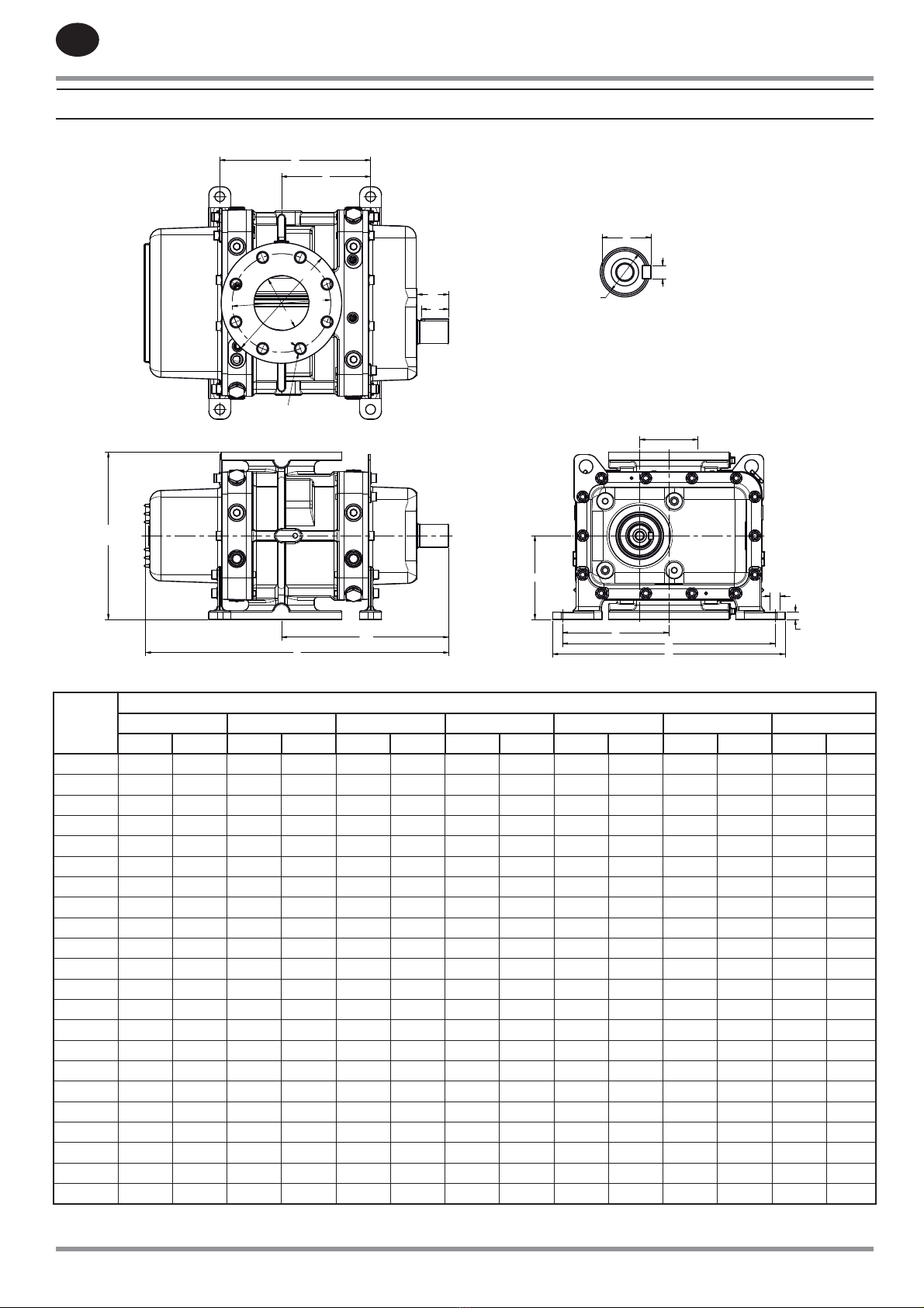
2.8 Connections
ø r
A
a
E
B
F
D
h
T
Z
Y
4 x ø P
G
L
L1
ø R
ø DN
ø S
V
W
EA / GC
n : number of holes
Figure 3 - Left and Right Hand blower dimensions
“Figure
3 Key”
Dimensions
NX 2 NX 3 NX 5 NX 8 NX 12 NX 18 NX 26
mm inch mm inch mm inch mm inch mm inch mm inch mm inch
A 205 8.07 275 10.83 370 14.57 355 13.98 476 18.74 444 17.48 589 23.19
a 102.5 4.04 162.5 6.40 213 8.39 208 8.19 278 10.94 222 8.74 339.5 13.37
B 388 15.28 388 15.28 388 15.28 475 18.70 475 18.70 586 23.07 586 23.07
D 424 16.69 424 16.69 424 16.69 515 20.28 515 20.28 626 24.65 626 24.65
E 305 12.01 305 12.01 305 12.01 370 14.57 370 14.57 450 17.72 450 17.72
EA/GC 106 4.17 106 4.17 106 4.17 135 5.31 135 5.31 173 6.81 173 6.81
F 194 7.64 194 7.64 194 7.64 238 9.37 238 9.37 293 11.54 293 11.54
G 13 0.51 13 0.51 13 0.51 13 0.51 13 0.51 15 0.59 15 0.59
h 152.5 6.00 152.5 6.00 152.5 6.00 185 7.28 185 7.28 225 8.86 225 8.86
L 485 19.09 555 21.85 650 25.59 671 26.42 791 31.14 848 33.39 993.2 39.10
L1 245 9.65 305 12.01 356 14.02 385 15.16 454 17.87 441 17.36 559 22.01
T 45 1.77 45 1.77 45 1.77 51.5 2.03 51.5 2.03 69 2.72 69 2.72
V 50 1.97 50 1.97 50 1.97 70 2.76 70 2.76 90 3.54 90 3.54
W 60 2.36 57 2.24 58 2.28 81 3.19 80 3.15 102 4.02 102.2 4.02
Y 12 0.47 12 0.47 12 0.47 14 0.55 14 0.55 18 0.71 18 0.71
ØZ* 42 1.65 42 1.65 42 1.65 48 1.89 48 1.89 65 2.56 65 2.56
ØR 200 7.87 220 8.66 220 8.66 250 9.84 285 11.22 340 13.39 340 13.39
Ør 160 6.30 180 7.09 180 7.09 210 8.27 240 9.45 295 11.61 295 11.61
ØDN 80 3.15 100 3.94 100 3.94 125 4.92 150 5.91 200 7.87 200 7.87
ØP 18 0.71 18 0.71 18 0.71 18 0.71 18 0.71 22 0.87 22 0.87
ØS 18 0.71 18 0.71 18 0.71 18 0.71 22 0.87 22 0.87 22 0.87
n 8 0.31 8 0.31 8 0.31 8 0.31 8 0.31 8 0.31 8 0.31
* Fitting tolerance range : m6
Table 11 - Left and Right hand blower dimensions
www.fraserwoods.ca
80446693 Rev. B EN-13
EN
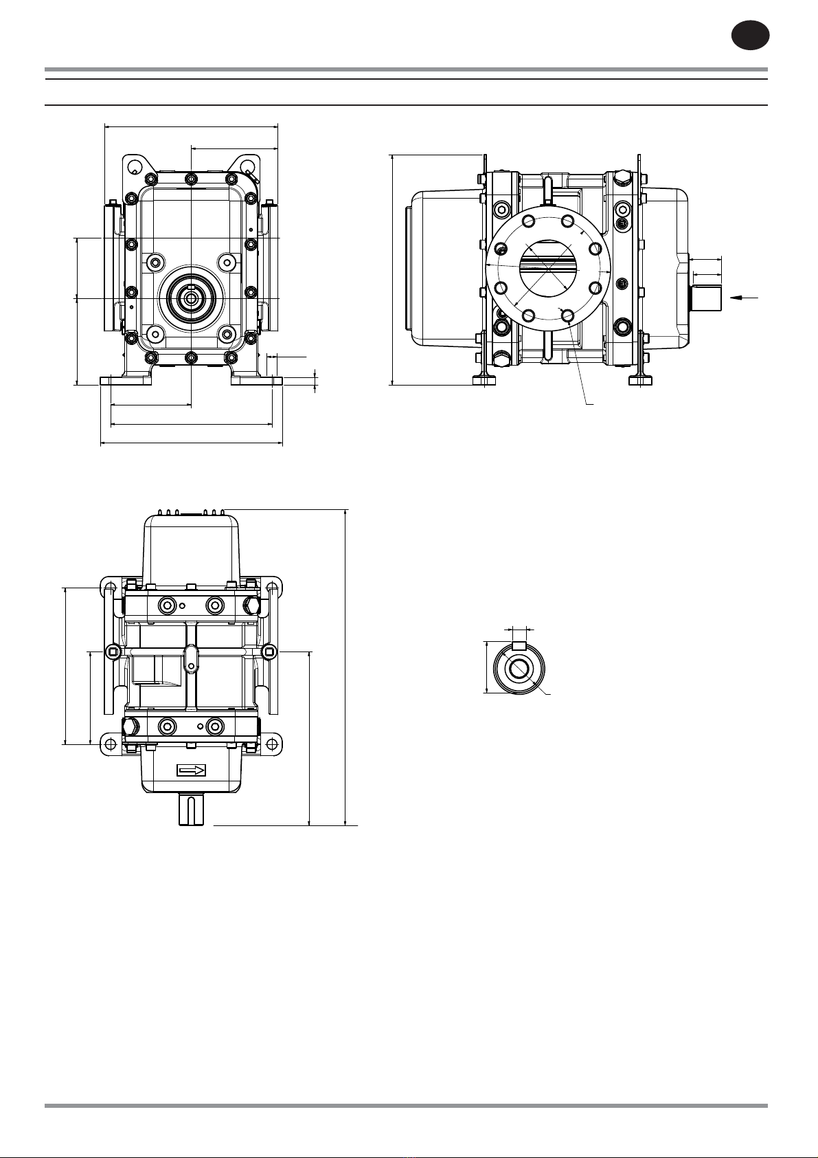
2. TECHNICAL DATA
Ø r
B
D
EA / GC
Y
X
T
Z
H
E
h
Ø R
Ø S
A
a
L1
L
F
4 x Ø P
V
W
Ø DN
G
F
Detail F
n : number of holes
Figure 4 -Top and Bottom Shaft blower dimensions
www.fraserwoods.ca

EN
EN-14 80446693 Rev. B
2. TECHNICAL DATA
“Figure
4 Key”
Dimensions
NX 2 NX 3 NX 5 NX 8 NX 12 NX 18 NX 26
mm inch mm inch mm inch mm inch mm inch mm inch mm inch
A 205 8.07 275 10.83 370 14.57 355 13.98 476 18.74 444 17.48 589 23.19
a 102.5 4.04 162.5 6.40 213 8.39 208 8.19 278 10.94 222 8.74 339.5 13.37
B 284 11.18 284 11.18 284 11.18 336 13.23 336 13.23 414 16.30 414 16.30
D 320 12.60 320 12.60 320 12.60 376 14.80 376 14.80 454 17.87 454 17.87
E 305 12.01 305 12.01 305 12.01 370 14.57 370 14.57 450 17.72 450 17.72
EA/GC 106 4.17 106 4.17 106 4.17 135 5.31 135 5.31 173 6.81 173 6.81
F 142 5.59 142 5.59 142 5.59 168 6.61 168 6.61 207 8.15 207 8.15
G 13 0.51 13 0.51 13 0.51 13 0.51 13 0.51 15 0.59 15 0.59
H 152.5 6.00 152.5 6.00 152.5 6.00 185 7.28 185 7.28 225 8.86 225 8.86
h 151.5 5.96 151.5 5.96 151.5 5.96 187 7.36 187 7.36 224.5 8.84 224.5 8.84
L 485 19.09 555 21.85 650 25.59 671 26.42 791 31.14 848 33.39 993.2 39.10
L1 245 9.65 305 12.01 356 14.02 385 15.16 454 17.87 441 17.36 559 22.01
T 45 1.77 45 1.77 45 1.77 51.5 2.03 51.5 2.03 69 2.72 69 2.72
V 50 1.97 50 1.97 50 1.97 70 2.76 70 2.76 90 3.54 90 3.54
W 60 2.36 57 2.24 58 2.28 81 3.19 80 3.15 102 4.02 102.2 4.02
X 404.5 15.93 404.5 15.93 404.5 15.93 499 19.65 499 19.65 589 23.19 589 23.19
Y 12 0.47 12 0.47 12 0.47 14 0.55 14 0.55 18 0.71 18 0.71
ØZ* 42 1.65 42 1.65 42 1.65 48 1.89 48 1.89 65 2.56 65 2.56
ØR 200 7.87 220 8.66 250 9.84 250 9.84 285 11.22 340 13.39 340 13.39
Ør 160 6.30 180 7.09 210 8.27 210 8.27 240 9.45 295 11.61 295 11.61
ØDN 80 3.15 100 3.94 125 4.92 125 4.92 150 5.91 200 7.87 200 7.87
ØP 18 0.71 18 0.71 18 0.71 18 0.71 18 0.71 22 0.87 22 0.87
ØS 18 0.71 18 0.71 18 0.71 18 0.71 22 0.87 22 0.87 22 0.87
n 8 0.31 8 0.31 8 0.31 8 0.31 8 0.31 8 0.31 8 0.31
* Fitting tolerance range: m6 unless otherwise stated above.
Table 12 -Top and Bottom Shaft blower dimensions
www.fraserwoods.ca
80446693 Rev. B EN-15
EN
Ingersoll Rand will accept no liability or warranty
claims if your installation includes any modications
or additions to the blower without the prior written
approval of Ingersoll Rand, or if the blower is incorrectly
installed.
3.1 Installation safety
WARNING
Obey the safety instructions listed below and take note
of appropriate precautions when you install the blower.
A suitably trained and supervised technician must install
the blower.
Ensure that debris and dust does not get into the blower or
the system pipelines when you install the blower.
Check that all of the required components and tools are
available and of the correct type before you start to install
the blower.
Use suitable new gaskets/seals to connect the blower into
your system. Do not re-use old gaskets/seals.
If you will t the blower into an existing system, disconnect
the power from the drive system before you start
installation, so that the drive system cannot be operated
accidentally.
3.2 System design and safety
WARNING
Ensure that the maximum dierential pressure across
the blower specied in section 2.2 cannot be exceeded.
If it is, the drive will trip and the blower will stop. Obey
the safety instructions listed below when you design
and build your system:
3.2.1 General requirements
Your system must be suitably designed for correct operation
of the blower. Note that:
You must design a suitable pipeline to t the blower inlet/
outlet connections. refer to Section 2.8 and to Figures 3
and 4 for the dimensions of the blower connections.
Your system design must ensure that, when the blower
is in its nal operating location, you can see the oil-level
sight-glasses and can access the oil ller and drain plugs.
Your system must incorporate a suitable mounting
platform: see Section 3.4 for more details.
The blower must be suciently level for correct operation:
see Section 3.4 for more details.
There must be at least 150 mm (6 inches) of free space
around the blower, for adequate cooling-air circulation.
•
•
•
•
•
•
•
•
•
•
•
The gases which enter the blower must not contain solid
particulates larger than 25 m (9.84 x 10⁻⁵ inch) in size and
must not contain more than 200 mg/m3 (1.37 x 10⁻⁵ lb/ft3)
of dust. Incorporate suitable lters to prevent the ingress
of solids into the blower.
The temperature of the gases which enter the blower must
not exceed the temperature rating of the blower.
3.2.2 System safety
Your system design must ensure that the blower cannot
be operated with the inlet or discharge (outlet) pipelines
obstructed.
Ensure that the blower cannot operate with the incorrect
direction of rotation (see Section 3.7).
We also recommend that your system incorporates an
emergency stop facility which, once activated, must be
manually reset before the blower can be operated again.
Your system must incorporate non-return valves (check
valves), to prevent reverse rotation of the blower when it is
switched o.
Your system must incorporate a pressure relief valve in the
outlet pipeline (for pressure operation) and/or incorporate
a vacuum relief valve in the inlet pipeline (for vacuum
operation), to ensure that the design capability of the
blower cannot be exceeded during operation. The relief
valve(s) must be suitably rated/sized for the performance
of the blower.
We recommend that you incorporate silencers, to
attenuate the pulsations in the inlet/outlet gas streams.
If required, install your own acoustic enclosure around
the blower or ensure that people wear suitable protective
equipment (such as ear defenders) when they are close
to the operating blower (See section 2.4). If you install an
acoustic enclosure, ensure that there is sucient space for
cooling-air ow around the blower. See above
Your design must ensure that people are protected from
accidental contact with the blower or the outlet pipelines.
During blower operation, the temperature of the blower
and the outlet pipelines will be above 70 °C (158 °F). If
necessary, t suitable guards.
Your design must ensure that materials or substances
which are ammable at temperatures of 70 °C (158 °F) or
above are not close to, or in contact with, the hot blower or
outlet pipelines.
If you pump/compress ammable or toxic gases, you must
take suitable precautions to prevent the discharge of the
gases to the surrounding atmosphere.
Note: Filters, pressure/vacuum relief valves, non-return (check)
valves, acoustic enclosures and silencers are available from
Ingersoll Rand: contact your supplier or Ingersoll Rand for
advice.
•
•
•
•
•
•
•
•
•
•
•
•
•
3. INSTALLATION
www.fraserwoods.ca

EN
EN-16 80446693 Rev. B
3. INSTALLATION
3.3 Unpack and inspect
WARNING
Use suitable lifting equipment to move the blower.
If you do not, you can injure yourself or damage the
blower. Refer to Section 2.2 for the mass of the blower.
1. Use a suitable fork-lift truck or pallet truck to move the
blower, on its pallet, close to where you will install it.
2. Remove all packing materials and protective covers
and check the blower. If the blower is damaged, notify
your supplier and the carrier in writing within two
days; state the Item Number of the blower together
with your order number and your supplier’s invoice
number. Retain all packing materials for inspection. Do
not use the blower if it is damaged.
3. Check that you have received the items. If any item is
missing, notify your supplier in writing within two days
4. Look at the blower rating and identication plate
(Figure 1, item 13) and check that the blower is suitable
for use in your system. If the blower is not suitable
for use in your system, do not continue to install the
blower: contact your Supplier or
Ingersoll Rand.
If the blower is not to be used immediately, replace the
protective covers. Store the blower in suitable conditions, as
described in Section 6.1.
3.4 Prepare, locate and connect the blower
3.4.1 Introduction
Take note of the following when you locate the blower and
connect it into your system:
For optimum performance, ensure that the system
pipelines connected to the blower are as short as possible.
Support your system pipelines and other components, to
prevent loading of the inlet and outlet ports on the blower.
Incorporate exible components in your system, to
minimise noise and vibration.
Where necessary, use gaskets/seals which are compatible
with the gases which will be pumped/compressed, and
with the operating conditions.
The leak tightness of your system connections must be in
accordance with the requirements of your applications.
Note that blowers can be:
Installed directly in your system. You must ensure that your
system pipelines can support the blower. Prepare, locate
and connect blower as described in Section 3.4.2.
Supported by mounting feet; prepare, locate and connect
blowers as described in Section 3.4.3.
•
•
•
•
•
•
•
•
•
Note that the blowers are supplied with either lifting bolts
tted (as shown in Figure 1) or with lifting lugs tted. Where
necessary in Sections 3.4.2 or 3.4.3, attach your lifting
equipment to these lifting bolts/lugs.
3.4.2 Prepare, locate and connect blowers
installed directly in your system
WARNING
Use suitable lifting equipment to move the blower.
If you do not, you can injure yourself or damage the
blower. Refer to Section 2.2 for the mass of the blower.
Note: The following procedure assumes that your system inlet
pipeline will support the blower. If your blower will be supported
by your system outlet pipeline, reverse Steps 4 and 5 below.
Use the following procedure to prepare, locate and connect
blower:
1. Use a suitable cleaning solution (such as alcohol or
white spirit) to clean the rotors:
Moisten a suitable clean, lint-free cloth with the
cleaning solution.
Clean the rotors (Figure 1, item 8) which are visible
through the inlet port.
Turn the blower drive shaft as necessary to access the
other rotors.
2. Refer to Figure 1. Attach suitable lifting equipment to
the blower, then use the lifting equipment to move the
blower to its required operating location.
3. While it is supported by the lifting equipment, adjust
the position of the blower so that the blower inlet and
outlet are correctly aligned with the connections in
your system inlet and outlet pipelines.
4. Fit a suitable gasket/seal* to the blower inlet (Figure 1,
item 2), then use the correct number and size of bolts
to connect the blower inlet ange to your system inlet
pipeline.
5. Fit a suitable gasket/seal* to your system outlet
pipeline, then use the correct number and size of bolts
to connect the blower outlet ange to your system
outlet pipeline.
6. Disconnect your lifting equipment from the blower.
*Note: Gaskets are available from Ingersoll Rand:
Contact your supplier or Ingersoll Rand for advice
•
•
•
•
www.fraserwoods.ca
80446693 Rev. B EN-17
EN
3. INSTALLATION
3.4.3 Prepare, locate and connect a blower
supported by mounting feet
WARNING
Use suitable lifting equipment to move the blower.
If you do not, you can injure yourself or damage the
blower. Refer to Section 2.2 for the mass of the blower.
You must provide a rm, level platform for the blower. Ensure
that the operating location is clean and free from debris and
oil.
You must ensure that when the blower is in its required
operating location, all of the mounting feet (1, 2 or 4,
depending on the blower model) are at on the mounting
platform to within 0.1 mm.m ¯ (0.0013 inch.ft ¯ ).
Use the following procedure to prepare, locate and connect
the blower:
1. Refer to Figure 1. Attach suitable lifting equipment to
the four lifting-bolts (1), then use the lifting equipment
to move the blower to its required operating location.
2. Disconnect your lifting equipment from the blower. If
required, remove the lifting-bolts from the blower.
3. Fit suitable bolts through the xing holes in the
mounting feet (Figure 1, items 9), to secure the blower
in position.
4. Clean the rotors: refer to Step 1 of Section 3.4.2.
5. Use a suitable gasket/seal* to connect your inlet
pipeline to the blower inlet (Figure 1, item 2).
6. Use a suitable gasket/seal* to connect your outlet
pipeline to the blower outlet (Figure 1, item 3).
*Note: Gaskets are available from Ingersoll Rand:
Contact your supplier or Ingersoll Rand for advice
•3.5 Fill the blower with oil
Ensure that you use the correct grade of oil and that
the oil levels in the blower are correct. If you do not, the
blower will probably be damaged during operation, or
its performance may be aected.
1. Drain the protective oil from the drive end and non-
drive end covers: refer to Section 5.5.
2. Refer to Figure 1. Fill the drive end cover (4) with oil:
refer to Section 5.5.1.
3. Fill the non-drive end cover (12) with oil: refer to
Section 5.5.2.
3.6 Fit the drive/transmission
WARNING
You must t suitable guards to protect people from
rotating/moving parts.
Your drive and transmission system design must ensure
that the maximum blower rotational speeds specied in
Section 2.3 cannot be exceeded, otherwise the blower
will be damaged, or may not operate correctly.
You must use a suitable coupling or a belt drive and
transmission system to connect your drive to the blower.
Your drive and transmission system design must ensure that
the radial and axial loadings on the blower drive shaft are as
low as possible.
Note: For this, the blower pulley diameter must be above
diameters specied in Table 13, linear speed of belts should not
exceed 31 m/s and transmission safety factor should be between
1,4 and 1,7.
Connect the components of the drive and transmission
system to the blower drive shaft (Figure 1, item 5) as
described in the manufacturer’s instructions supplied with
the components.
Blower
Minimum pully diameter for specied dierential pressure : mm (inch)
“300 mbar
3 x 10 Pa
4,35 psi”
“400 mbar
4 x 10 Pa
5,8 psi”
“500 mbar
5 x 10 Pa
7,25 psi”
“600 mbar
6 x 10 Pa
8,7 psi”
“700 mbar
7 x 10 Pa
10,15 psi”
“800 mbar
8 x 10 Pa
11,6 psi”
“900 mbar
9 x 10 Pa
13,05 psi”
“1000
mbar
1 x 10 Pa
14,5 psi”
NX 2 100 (3.94) 100 (3.94) 100 (3.94) 100 (3.94) 100 (3.94) 112 (4.41) 112 (4.41) 125 (4.92)
NX 3 100 (3.94) 100 (3.94) 100 (3.94) 112 (4.41) 112 (4.41) 125 (4.92) 125 (4.92) 150 (5.90)
NX 5 125 (4.92) 125 (4.92) 125 (4.92) 150 (5.90) 150 (5.90) 160 (6.30) 170 (6.69) 180 (7.09)
NX 8 140 (5.51) 140 (5.51) 150 (5.90) 160 (6.30) 170 (6.69) 180 (7.09) 180 (7.09) 200 (7.87)
NX 12 170 (6.69) 170 (6.69) 180 (7.09) 200 (7.87) 212 (8.35) 212 (8.35) 224 (8.82) 224 (8.82)
NX 18 150 (5.90) 150 (5.90) 160 (6.30) 170 (6.69) 180 (7.09) 200 (7.87) 200 (7.87) 224 (8.82)
NX 26 170 (6.69) 170 (6.69) 180 (7.09) 200 (7.87) 212 (8.35) 212 (8.35) 224 (8.82) 250 (9.84)
Table 13 - Minimum drive shaft pulley diameters
www.fraserwoods.ca

EN
EN-18 80446693 Rev. B
3. INSTALLATION
3.7 Check the direction of rotation
WARNING
If you remove a guard during the following procedure,
ensure that you do not corne into contact with the shaft,
the coupling/belt or the drive system when you operate
the blower.
If you do, you may be injured by the rotating
components.
Ensure that the blower rotates in the correct direction. If
it does not, your system will not operate correctly.
After you have connected the drive/transmission, check the
direction of rotation of the blower as follows:
1. Ensure that isolation valves in the blower inlet and
outlet pipelines are in the correct‘open’positions.
2. If necessary (that is, to make it easier to see the blower
drive shaft), temporarily remove guard over the drive
coupling or belt.
3. Refer to Figure 1. Watch the blower drive shaft (5) while
you start up the blower (refer to Section 4.2), then
shut down the blower (refer to Section 4.3) after two
seconds.
4. Check that the blower drive shaft (5) rotated correctly
in the expected direction. (This depends on your
application and installation conguration: see Figure 1
item 15a or b)
5. If the direction of rotation was incorrect:
Check the installation of the drive and transmission
system and recongure as appropriate.
Perform the direction of rotation check from Step 2
again, to ensure that the blower now rotates in the
correct direction.
6. If you have removed the guard over the drive coupling
or belt (as in Step 1 above), ret the guard.
•
•
3.8 Commissioning the blower
After you have installed the blower, use the following
procedure to commission it and prepare it for subsequent
operation:
1. Ensure that isolation valves in the blower inlet and
outlet pipelines are in the correct‘open’positions.
2. Ensure that all other components in the system
pipelines (such as lters) have been correctly installed
and congured for operation.
3. Engage your drive and transmission system to start the
blower.
4. Operate the blower, with no gas load, for at least 15
minutes. During this time:
Monitor the external surfaces of the blower and check
for‘hot spots’(that means, areas which are unusually
hot).
If any hot spots persist at the end of the 15 minutes,
contact your supplier or Ingersoll Rand for advice.
5. Continue to operate the blower with a representative
gas load, and check that it operates correctly and
provides the required performance. If necessary, refer
to Section 5.7 if any fault conditions occur.
6. Disengage your drive and transmission system to stop
the blower.
7. Wait until you can hear that the blower has stopped
before you close any isolation valves in the blower inlet
and outlet pipelines.
The blower is now ready for normal operation.
•
•
www.fraserwoods.ca

80446693 Rev. B EN-19
EN
4. OPERATION
WARNING
Ingersoll Rand will accept no liability or warranty
claims if your blower is used on applications or in a
way prohibited in this manual, or not specied in this
manual.
4.1 General operational safety
WARNING
Obey the safety instructions and precautions listed
below. If you do not, there may be a risk of injury or
death to people, or damage to the blower.
Do not expose any part of your body to vacuum. If you do,
you may be injured.
Do not operate the blower when the cooling-air ow
around the blower is restricted (see Section 3.2). If you do,
the blower may overheat.
Do not operate the blower with the blower inlet or outlet
ports open to the atmosphere. If you do, your ngers or
other parts of your body or clothing may get trapped, and
you may be injured by the rotating mechanisms in the
blower.
Do not operate the blower with the guards removed from
the blower drive shaft, the coupling/belt or the drive
system. If you do, your ngers or other parts of your body
or clothing may get trapped, and you may be injured by
the rotating components.
Never disconnect any of the connecting pipelines (for
example, the pipeline connected to the inlet) when the
blower is operating.
Prevent accidental contact with the hot blower, and do
not place ammable materials on the blower. During
operation, the temperature of external parts of the blower
can exceed 70° C (158° F).
Do not attempt to use the blower to pump/compress
liquids. The blowers are not designed for this application.
Where necessary (for example, if you have not tted an
acoustic enclosure), wear suitable ear defenders. The
blower can be noisy during operation (refer to Section 2.4).
During pressure operation, prevent accidental contact with
the discharged (outlet) gas stream. This gas stream will be
at high pressure and will be hot and cause burn injury.
•
•
•
•
•
•
•
•
•
4.2 Start-up
Ensure that the oil levels in the blower are correct. If you
do not, the blower will probably be damaged during
operation, or its performance may be aected.
1. Ensure that any isolation valves in the blower inlet and
outlet pipelines are in the correct‘open’positions.
2. Check the oil-levels in the blower: refer to Section 5.3.
3. Engage your drive and transmission system to start the
blower.
You can now use the blower as required in your application.
4.3 Shut-down
1. Disengage the drive and transmission system to stop
the blower.
2. Wait until you can hear that the blower has stopped
before you close any isolation valves in the blower inlet
and outlet pipelines.
www.fraserwoods.ca
EN
EN-20 80446693 Rev. B
5. MAINTENANCE
5.1 Safety information
WARNING
Obey the safety instructions given below and take note
of appropriate precautions. If you do not, you can cause
injury to people and damage to equipment.
A suitably trained and supervised technician must
maintain the blower. Obey your local and national safety
requirements.
Ensure that the maintenance technician is familiar with
the safety procedures which relate to the gases pumped/
compressed by the system in which the blower is installed.
Allow the blower to cool to a safe temperature before you
start maintenance work.
Isolate the blower from the drive system so that it cannot
be operated accidentally.
Recheck the blower rotation direction (see Section 3.7) if
the drive and transmission system has been disconnected
and then reconnected.
Take care to protect the inlet/outlet port sealing faces from
damage.
Do not re-use seals/gaskets if they are damaged.
Check the tightness of the system connections after
maintenance work is complete if you have connected
or disconnected any suction inlet or discharge (outlet)/
injection joints. The tightness of the system connections
must be in accordance with the requirements of your
applications.
5.2 Maintenance plan
The plan in Table 14 details the maintenance operations
required to maintain the blower in normal operation.
Instructions for each operation are given in the section
shown.
Note that:
If you use a mineral oil in the blower: you must change the
oil every 2000 hours of operation or once a year.
If you use a synthetic oil in the blower, you must change
the oil every 12 months.
If you use a Hibon Lube in the blower and you operate the
blower with a discharge (outlet) temperature above 120 ˚ C
(248 ˚ F), you must change the oil every 12 months.
If you use a Hibon Lube in the blower and you operate the
blower with a discharge (outlet) temperature below 120 ˚ C
(248 ˚ F), you must change the oil every two years.
When you maintain the blower, use Ingersoll Rand spares:
refer to Section 7.3.
•
•
•
•
•
•
•
•
•
•
•
•
Operation Frequency Refer to
Section
Check the oil levels
Inspect the system installation
Change the oil
Overhaul the blower
Weekly
Monthly
See Section 5.2
4 yearly
5.3
5.4
5.5
5.6
After blower installation, the oil must be changed after 200
hours of running.
Table 14 – Maintenance plan
5.3 Check the oil levels
Ensure that you use the correct grade of oil and that
the oil levels in the blower are correct. If you do not, the
blower will probably be damaged during operation, or
its performance may be aected.
5.3.1 Inspect the oil-level sight-glasses
1. Refer to Figure 1. Look at the oil-level sight-glass (6) on
the drive head plate (4):
If the sight-glass is dirty, use a suitable cloth to wipe it
clean.
If the sight-glass is damaged (that is, scratched,
cracked or corroded), or if there are signs of oil
leakage from the sight-glass, you must replace it:
contact your supplier or Ingersoll Rand.
2. Look at the oil-level sight-glass (11) on the non-drive
head plate (12):
If the sight-glass is dirty, use a suitable cloth to wipe it
clean.
If the sight-glass is damaged (that is, scratched,
cracked or corroded), or if there are signs of oil
leakage from the sight-glass, you must replace it:
contact your supplier or Ingersoll Rand.
5.3.2 Drive Head Plate
1. Refer to Figure 1, detail B. Look at the oil level in the
sight-glass (6) on the drive head plate (4):
If the oil level is below the minimum level mark (19),
continue at Step 2 to add more oil.
If the oil level is above the maximum level mark (18),
drain oil from the blower until the level is correct: refer
to Section 5.5.
2. Refer to Figure 1. Remove the oil ller-plug (16) from
the ller port on the top of the drive head plate (4).
3. For new oil of the correct type (see Section 2.6)
through the ller port and into the head plate until
the oil-level reaches the maximum level mark (detail B,
item 18). If the oil level goes above the maximum level
mark (18), drain oil from the blower until the level is
correct: refer to Section 5.5.
4. Ret the oil ller-plug (16) to the ller port on the top
of the drive head plate (4).
•
•
•
•
•
•
•
•
www.fraserwoods.ca
This manual suits for next models
6
Table of contents


