07
Step 5
Adjust and fix the Outdoor Antenna
Step 6
Install the indoor antenna
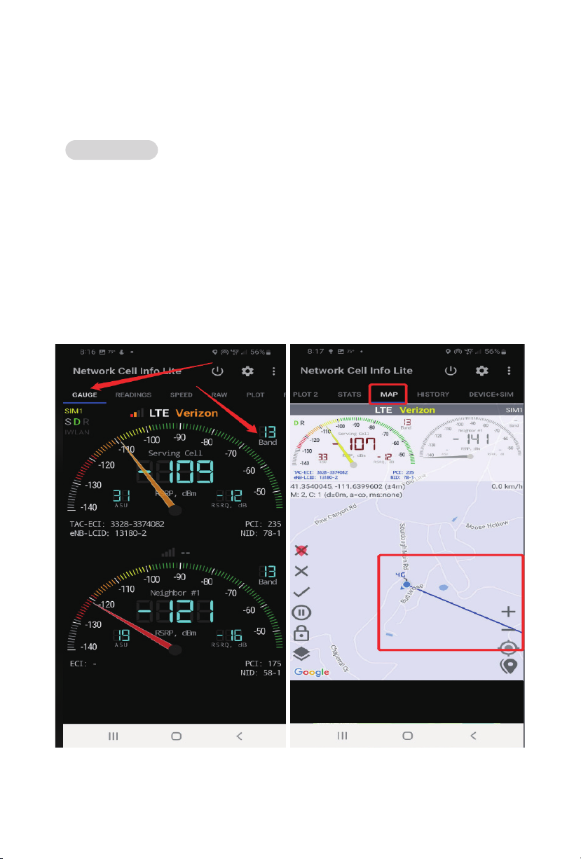
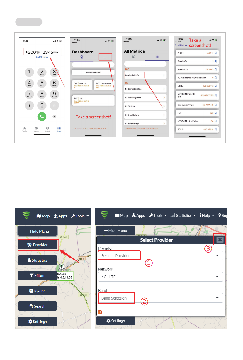
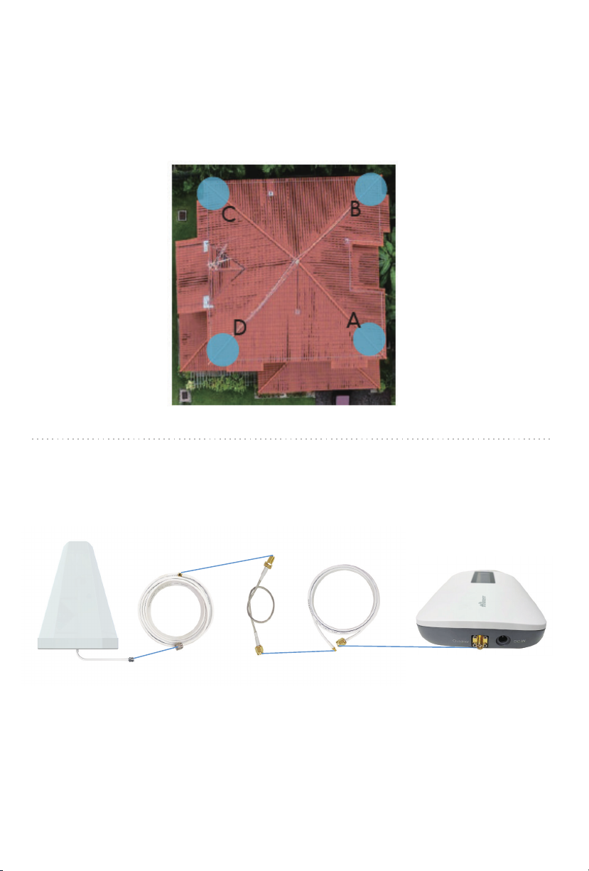
Have your outdoor antenna pointed to the cell tower
you found before and observe the reading on the
app. Adjust the outdoor antenna accordingly.
Notes:
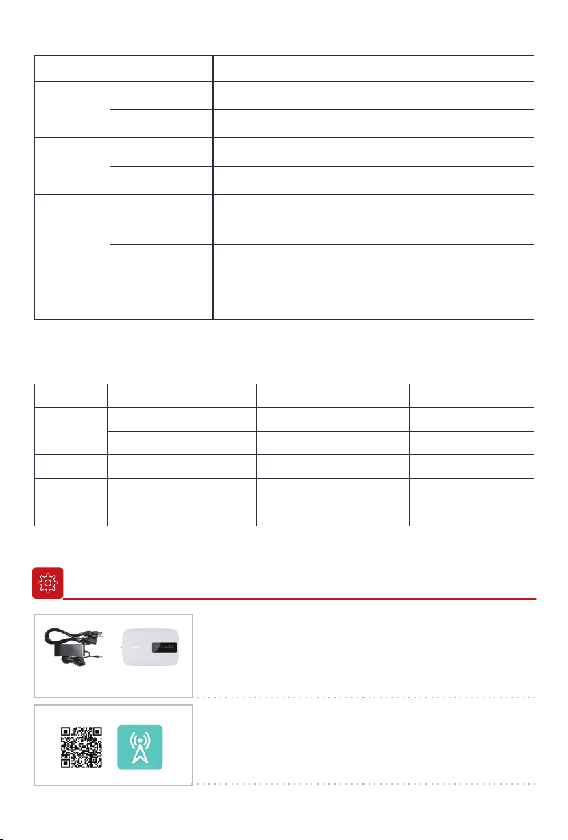
(1) The output power should be the higher the better.
(2) The full output power for Hero is 12dBm. And the full
gain is 65dB.
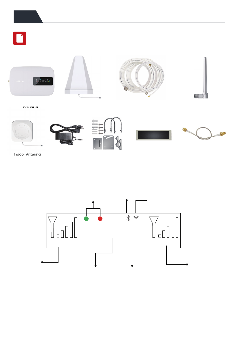
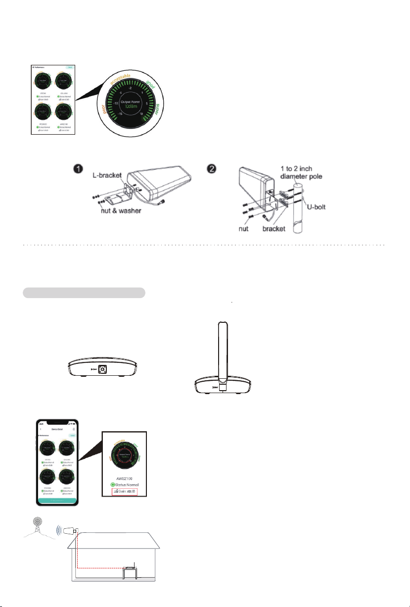
Indoor port
Place the signal booster on a dry and cool desktop,
make sure the booster is within the coverage area,
and it shall be easily accessible for maintenance.
(As the whip antenna is a kind of omni antenna, it is
suggested that the booster should be placed on a
desk in the center of a room, rather than on a wall)
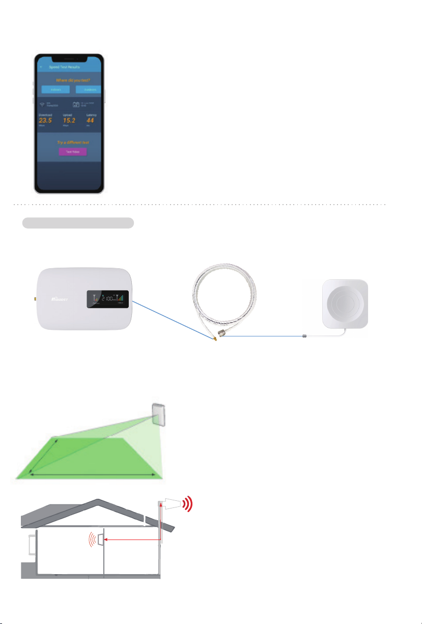
There are 2 types of indoor antennas in kit Hero---whip antenna and panel antenna. You
can choose either one to install.
Notes:
Make sure the gain reaches about 60dB. If not, please
increase the vertical and horizontal distance between
the two antennas or add some barriers.
6.1 Connect the indoor antenna with the booster
6.2 Adjust the indoor antenna
Indoor Whip Antenna
(omnidirectional)
Option 1 Desktop Mounted