Hickory N/5.5 G User manual

4900 Westside Avenue, North Bergen, New Jersey 07047
Tel: [201] 223-0050 Fax: [201] 223-0950
Hickory Industries, Inc.
N/5.5 Installation 8/5/97
Page 1 of 18
HickoryRotisseries USA
InstallationManual
Models: N/5.5G
TotalPowerRating
Burner / Spits
GasCategory
Fittings
Ignition
DeliveryDate:
MachineType N / 5. 5 G
20,000Btu
1 Burners with 5Spits
NaturalGas,LPG
1Infra-RedGasGenerators
1 Electronic Ignitor
FinalInspection:

4900 Westside Avenue, North Bergen, New Jersey 07047
Tel: [201] 223-0050 Fax: [201] 223-0950
Hickory Industries, Inc.
N/5.5 Installation 8/5/97
Page 2 of 18
1.0InstallationInstructions 3
1.1 GeneralInformation 4
1.2 DescriptionoftheDataPlate 4
1.3 MachineDrawingsandDimensions 5
1.4 ConversionandAdjustmentInstructions 6
1.5 AdjustmentsandVerificationforusewithNaturalGas 6
1.6 NaturalGasFlowTable(Consumption) 7
1.6.1 VolumetricMethodtoVerifytheFlameSetting,Mathematical 7
1.7 OrificeDiameters,ElectronicIgnitionSettings 8
1.8 ChangingGasOrifices 8
1.8.1 ChangingtheGasOrifice-GasGenerators 8
1.8.2 ChangingtheGasOrifice-PipeBurner 8
1.9 IgnitionCycle 8
1.10.1 AdjustingtheIgnitionElectrode 8
1.10 CheckingtheConnectedGasPressure(NominalPressure) 9
1.10.1 AdjustingtheIgnitionElectrode 9
1.11 Maintenance,ResponsetoTechnicalProblems 10
1.12 SpitDriveMechanism 11
1.12.1 Reasonsforproblemsandsolutions 12
1.13 SpitDriveMechanism 13
1.14 TestingandCheckingforSafety 14
1.15 DescriptionoftheElectricalConnection 14
1.16 ElectricalDiagram 15
1.17 5.5GPartsList 16
1.18 ExplodedViewDiagrams 18
TableofContents

4900 Westside Avenue, North Bergen, New Jersey 07047
Tel: [201] 223-0050 Fax: [201] 223-0950
Hickory Industries, Inc.
N/5.5 Installation 8/5/97
Page 3 of 18
a. Wheninstallingtheseunits,itisimportanttocomplywiththemostrecently
establishedrulesandregulationsasdeemedpertinentbythelocalandnational
electrical,gas,ventilation,sanitation,andfirecodes. Theseunitsareclassified
byUnderwritersLaboratories,Inc.asGas-FiredFoodServiceEquipmentin
accordancewithAmericanNationalStandardsInstituteANSIZ83.11b-1991,Gas
FoodServiceEquipment-RangesandUnitBoilers.
b. Gasunitsmustnotbedirectlyconnectedtoagasflueorexhaust. However,both
electricandgasunitsmayrequireoperationinconjuctionwithacanopytypeexhaust
hoodifdeemednecessarybylocalauthorities.
c. Theunitsmustbeinstalledinsuchawaythatproperventilationandheatexchangeis
assured. Theroommustbeventilatedinaccordancetothevalidcodesand
regulations.
d. Theunitsaretobeinstalledsecurelyandhorizontally. Theunitsmaybeinstalledon
combustiblefloors. Theunitsmustbeinstalledwithadjustablelegsifplacedona
combustiblesurface.
e. Theminimumclearancetotherearorsidewallsmustbe13inches. Itisalso
importanttoinsurethatthebottomoftheunitsiskeptclearsothat properventilation
orairexchangecanoccur.
f. Normally,theunitswillbesenttotheoperatoralreadysetupfortheparticular
typeofgasorelectricalserviceavailableattheirlocation. However,unlessotherwise
specified,thegasunitswillbesetupfornaturalgasuse(includinganelectricalcord
for120V,1Phase,60Hzoperation)andtheelectricunitsfor208V,3Phase,60Hz
electricaluse. Beforeinstallingandusingtheunitsforthefirsttime,itisimportantto
makesurethatthegastypeand/orelectricalpowerindicatedonthedataplate
matchesthetypeofgasandelectricalpoweravailableinthelocation. Shouldthisnot
bethecase,itisimperativetochangeorconverttheunitstotheneededtypes.
g. Thegasunitsmustbefittedwiththemanualshut-offgascock(valve)andpressure
regulatorsuppliedwiththemachine. Thismanualvalveisneededtoshutoffthegas
tothemachineduringmaintenancework,repairs,andiftheunitneedstobe
disconnectedforanyreason. Thepressureregulatorisneededtoadjustthegas
pressureenteringtheunittoensuretheproperoperationoftheunit.
Electricunitsmustbehard-wiredorfittedwithapowercordbyalicensedelectrician.
i. Dependingonlocalcodesorifdeemednecessary,agasfiltermayalsoberequired
forgasunits.
1.0 InstallationInstructions

4900 Westside Avenue, North Bergen, New Jersey 07047
Tel: [201] 223-0050 Fax: [201] 223-0950
Hickory Industries, Inc.
N/5.5 Installation 8/5/97
Page 4 of 18
1.1 GeneralInformation
TheOperatingInstructionsaretobegiventotheoperatoroftherotisserie. Allunit
operatorsaretobefamiliarwiththefunctionsoftherotisserie.
TheOperatingInstructionsshouldbekeptinalocationclosetotherotisserie. Itshouldbe
easilyrecognizeableandeasilyaccessible.
ThegasrotisseriescanbeusedwithbothnaturalandLPGgases. Therotisseriescanbe
convertedoradjustedtoanytypeofthelocallydistributednaturalandLPGgases.
Electricunitscanbeorderedtomeetmostelectricalspecifications.
Itisrecommendedthatarepairandmaintenancecontractbesignedwiththe
manufacturer'sagent,distributor,orserviceagency.
1.2 DescriptionoftheDataPlate
WARNING!
Thisunitmustbeinstalledandconnectedinaccordancetothelatestregulations
andcanonlybeoperatedinconjunctionwithforcedventilationorexhausthood.
Thisunithasbeendesignedforprofessionaluseonly
andmayonlybeinstalledorrepairedbylicensedserviceagencies!
Beforeinstallingorusingthisequipment,readtheseinstructions!
Model: 5.5 G Serial No.
HickoryIndustries,Inc.
CommercialCookingAppliances
NorthBergen,NJ 07047
Motor: 110 - 115 VAC, 50/60 HZ, 3 RPM
Gas: NAT
Burners: 1
BTU/H
ManifoldPressure: 5"Naturalor10-11"Propane
20,000
Phase: 1
LISTED
69D6
MinimumInstallation Clearance
Sides: 13" Back: 13"
Maximum Lamp Wattage: 40 Watts
HickoryIndustries,Inc.
CommercialCookingAppliances
NorthBergen,NJ 07047
Model: 5.5 G Serial No.
Motor: 110 - 115 VAC, 50/60 HZ, 3 RPM
Gas: LPG
Burners: 1
BTU/H
ManifoldPressure: 5"Naturalor10-11"Propane
17,000
Phase: 1
LISTED
69D6
MinimumInstallation Clearance
Sides: 13" Back: 13"
Maximum Lamp Wattage: 40 Watts

4900 Westside Avenue, North Bergen, New Jersey 07047
Tel: [201] 223-0050 Fax: [201] 223-0950
Hickory Industries, Inc.
N/5.5 Installation 8/5/97
Page 5 of 18
Front View Right Side View
1.3 MachineDrawingsandDimensions
ThefollowingdrawingoftheFrontView,SideView,andTopViewindicatewherethe
dimensionsaretakenandshouldbeusedtoplantheinstallationoftheunits.
N/ 5.5 G
Top View
Height 31.5" 800
Width 39.25" 997
Depth 22" 560
N/5.5 G inches mm
* Includes Gas Connection Attachments

4900 Westside Avenue, North Bergen, New Jersey 07047
Tel: [201] 223-0050 Fax: [201] 223-0950
Hickory Industries, Inc.
N/5.5 Installation 8/5/97
Page 6 of 18
1.4 GasConversionandAdjustmentInstructions
Beforeconvertingoradjustingthemachinetoanothertypeofgas,itisimperativethatthe
manualgascockbeturnedtothe"off"position. Theelectricalpowertothemachinesshould
alsobeturnedoff. Whenconvertingthegasgeneratorsforusefromonetypeofgasuseto
another,thegasorifice(orinjector)mustbechangedaccordingtothetableonpage8. In
addition,thespringinthepressureregulatorsuppliedwiththeunitmustbechangedsothatit
canoperateatothergaspressures. SpringsfortheregulatorcanbeorderedfromHickory
Industries.
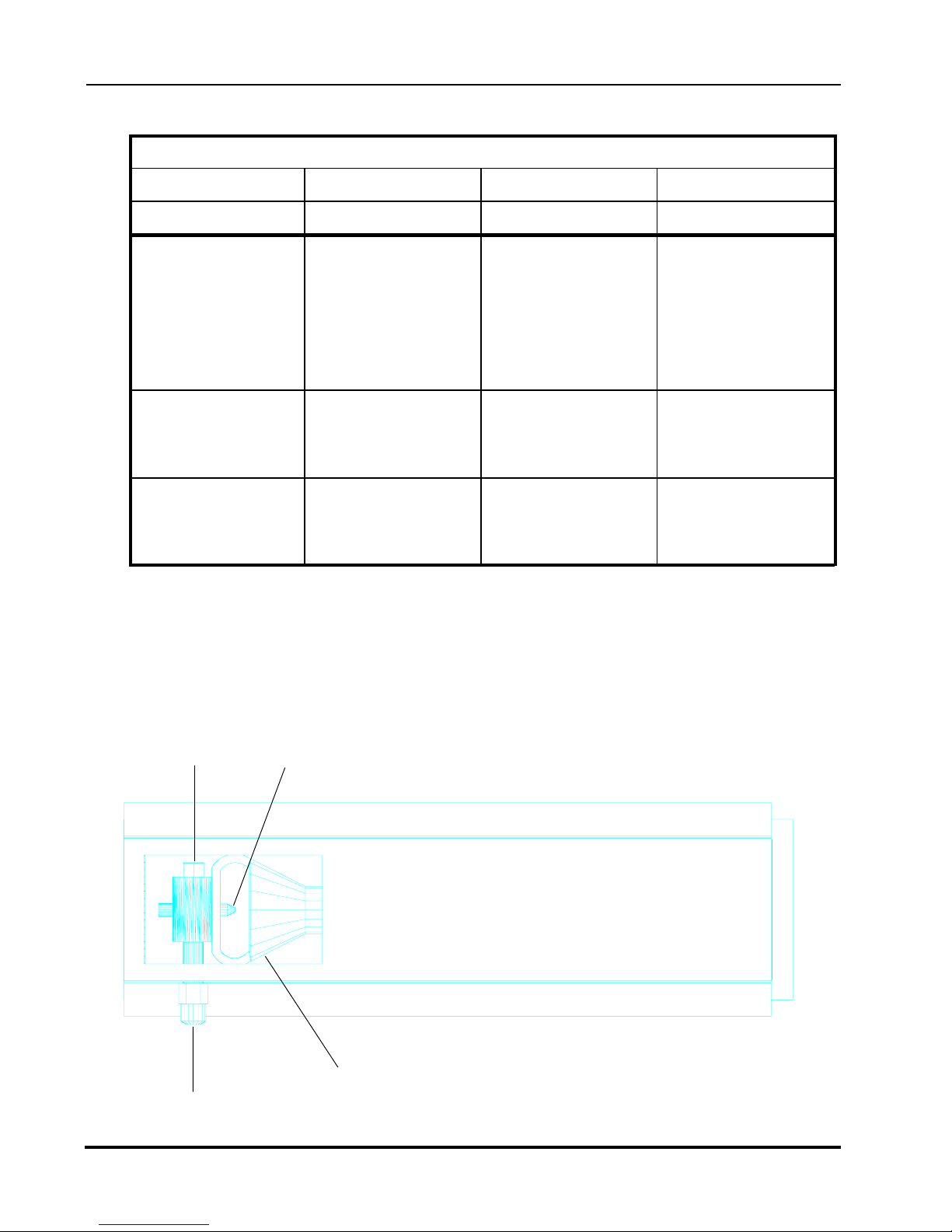
1.5 VerificationforusewithNaturalGas
Theflamesettingforthegasgeneratorcanbeconfirmedbyusing
thevolumetricmethodinconjunctionwiththemaingasmeter. Theburnerhasan
independentsolenoidgasvalve. ThevalveiscontrolledbyanindependentGaslite
sparkignitionmodule. Theamountofgasflowingthroughthevalvecannotbeadjusted
manually;thereisonlyan"on"or"off"position.
Tocarryoutthisverificationprocedure,itisnecessarytoobtaintheheatingvalue(BTU/ft3)
ofthelocalgasfromthelocalgascompany.
Avariationintheheatingvalueof thelocalgasfromthatonthetable(1.6)willresultin
avariationofthepoweroutputof theunit!
Ifthemeasuredgasvolumedoesnotcorrespondtothevaluesinthefollowingtable(1.6),the
itemswhichshouldbecheckedare:
A. Theincoming(connected)gaspressurewhiletheburnersandallotherappliances
inthelocationareoperational.
B. Ifthegaspressureiscorrect,itmustbeverifiedthatthepropersizegasorificesarein
place(seepage8).
Solenoid Valve
ConnectiontoIgnition
Module(Electrical)
GasInput
GasOutput
(connectiontoburner)

4900 Westside Avenue, North Bergen, New Jersey 07047
Tel: [201] 223-0050 Fax: [201] 223-0950
Hickory Industries, Inc.
N/5.5 Installation 8/5/97
Page 7 of 18
1.7.1 VolumetricMethodtoVerify theFlameSetting,Mathematical
WARNING! Noothergasequipmentcanbeinoperationduringthisprocedure.
Calculationofflow rateV inft3/hour
V = FP
Hi
V= Flow ratein ft3/minute
FP= HighFlamePowersettinginBTU/hr
Hi= HeatingvalueinBTU/ft3
Thus,fornaturalgas:
V=20,000 BTU/hr = 19.23ft3/hr = 0.32ft3/min.
1040 BTU/ft3
V= 0.32 ft3/min.
Thisisthenaturalgasneededin1hourbyaN/5.5G(1burner)atfullpower.
Thetimeandtheflowmeasurementsshouldbetakenatthegas(flow)meterwitha
chronometer(stopwatch).
Torunthetest,openthemanualgascockvalve,startuptheunitaccordingtothestart-up
instructions.
Allowtheunittopre-heat(burn)for10to15minutes. Verifythattheflowrateiscalibrated
totheappropriateflowrateindicatedinthetable.
Gas Flow - in ft3/hr
20,000 BTU - Natural
BTU/ft³
Heating Value in
Gas
HighFlameSetting
Natural
Propane
Butane 2480 6.85
1040 19.23
1.7 NaturalGasFlowTable
3215
17,000 BTU - LPG
5.28
4900 Westside Avenue, North Bergen, New Jersey 07047
Tel: [201] 223-0050 Fax: [201] 223-0950
Hickory Industries, Inc.
N/5.5 Installation 8/5/97
Page 8 of 18
TypeN/5.5 G
1.8 OrificeDiameters,ElectrodeGapSettings,andAirIntakeSettings
Gas/Pressure OrificeSize
Øindrill size
Natural/5.5"
inchesW.C.
Butane/11"
#46
#55
ElectronicIgnition
ElectrodeGap
1/8"Betweenrods
1/8"Betweenrods
andBurnersurface
1/8"Betweenrods
1/8"Betweenrods
andBurnersurface
Propane/11" #55 1/8"Betweenrods
1/8"Betweenrods
andBurnersurface
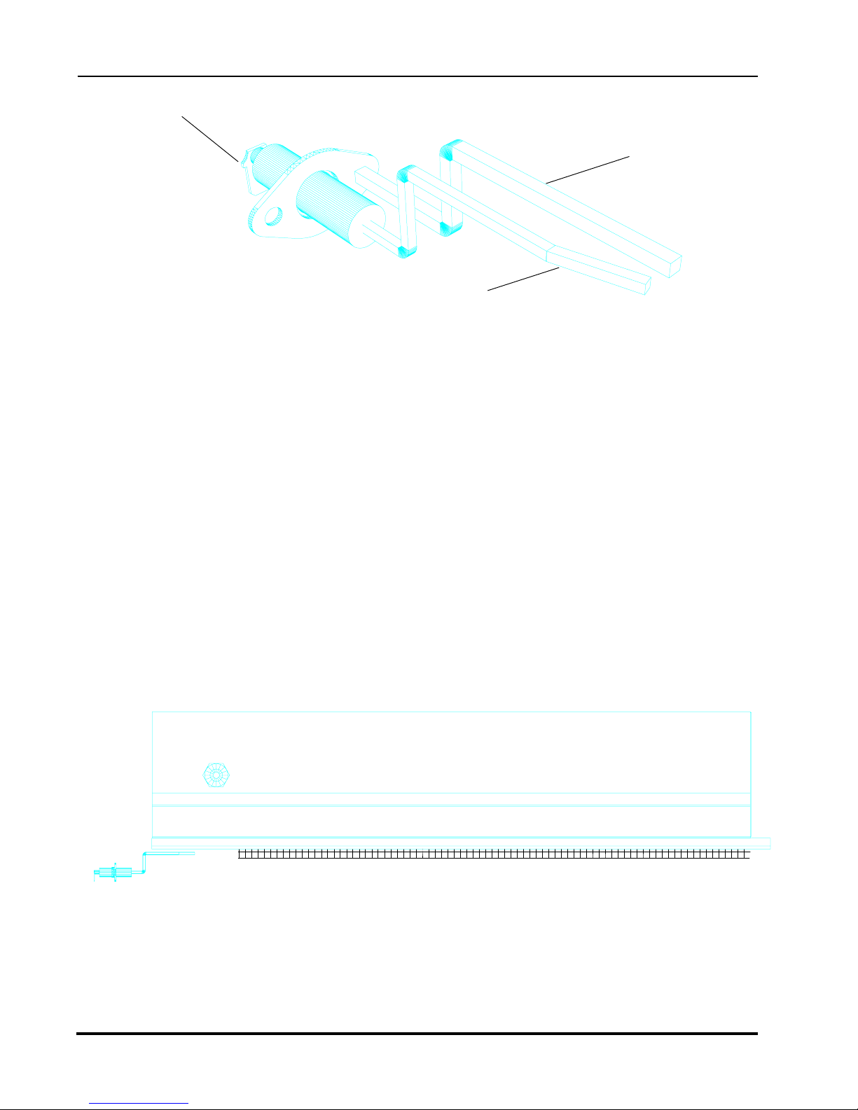
1.9 ChangingGasOrificesontheGasGenerators
TheN/5.5Gasunithasoneinfra-redgasgenerators. Thesegeneratorsuse ceramicradiating
plates.
The burner orifice can be removed and replaced using a 7/16" wrench. The orifice must be
sealed and tightly in place.
Gas Inlet Pipe
Alternate Opening for
Inlet Pipe Burner
Orifice
Venturi
Top View Gas Generator

4900 Westside Avenue, North Bergen, New Jersey 07047
Tel: [201] 223-0050 Fax: [201] 223-0950
Hickory Industries, Inc.
N/5.5 Installation 8/5/97
Page 9 of 18
1.10 IgnitionCycle
Inordertostartthecookingcycle,theburnersmustbeignited. Theignitioncyclewillstart
onlywhenthefollowingprocedureisfollowed:
a. The"HEAT"switchisturned to"on".
b. Acookingtemperaturemustbesetonthethermostat(i.e.450°F).
c. Thecookingtimermustbeactivated(seeOperatingInstructions).
Oncethesestepsarecompleted,theunitwillcallforheatandtheignitioncyclewillbe
activated. Theignitionsystemwillcausesparkingontheignitionelectrode. Oncethe
burnerislitbythespark,theflameoftheburnerwillheatthesensingprongontheignition
electrodesendingasignalbacktotheignitionmodule. Thissignalindicatesthatasparkis
nolongerneededandthatthesolenoidgasvalvemuststayopen. Whenthecooking
temperatureisreached,assensedbythethermocoupleattachedtothethermostat,the
electricalpowertotheignitionmoduleswillbecutoff,shuttingdowntheignitionmodule
andtheburners. Whenthetemperaturedropsbelowthesetpoint,electricalpowerissentto
theignitionsystemonceagain,thusstartingtheignitioncycleallover. Thesystemwill
cycleonandoffasneededtomaintainthesetcookingpoint.
Theignitionmoduleswillattempttoignitetheburnerthreetimes. Iftheburnersfailtolight
afterthreetries,themodulewilllock-out,shuttingdownallgasflowandfurthersparking.
Inordertostarttheignitioncycleafteralock-out,theheatswitchesandindividualburner
switchesmustbeturned"off"and"on"again. Thismayhavetobedoneseveraltimeswhen
startinguptheunitforthefirsttimeduetoairinthegaslines.
1.10.1 AdjustingtheIgnitionElectrode
Theignitionelectrodesareadjustedforanoptimumignitioncyclebeforetheunitleavesthe
factory. Ifforsomereasontheelectrodesneedadjusting(i.e.ifonetakesahitwithaspit),it
canbedoneasfollows.
1. Toreachtheignitionelectrode,openthefrontglassdoorsandremoveallspits.
2. Theelectrodeisattachedtothemainbodyofthemachinewithan8/32"screwand
nut. Itisimportantthatthisscrewmakesolidmetaltometalcontactbetweenthe
electrodecasingandthebodyoftherotisserie. Thismetaltometalcontactiswhat
actsasagroundingconductorforthegroundingprongontheignitionelectrode.
3. Duringtheignitionprocess,asolidbluesparkshouldtravelbetweenthetipofthetwo
electrodeprongs.
4. Makesurethatthedistancesbetweentheprongsandthesurfaceoftheburnerare
about1/8".
4900 Westside Avenue, North Bergen, New Jersey 07047
Tel: [201] 223-0050 Fax: [201] 223-0950
Hickory Industries, Inc.
N/5.5 Installation 8/5/97
Page 10 of 18
IgnitionElectrode
Grounding Prong
Ignition / Sensing Prong
Ignition Wire Connection
5. Ifthedistancesbetweentheprongsand/ortheburnersurfacearetoogreat,theunit
maysparkbutnotignitetheburner.
6. Whenadjustingtheprongs,makesuretosupportthebaseoftheprongwithonepair
ofpliersandadjustthetipoftheprongwithanotherpair. Thiswillpreventbreakage
oftheceramic casingoftheignition/sensingprong. Iftheceramiccasingdoesbreak,
theelectrodewillhavetobereplaced.
IgnitionElectrodePosition

4900 Westside Avenue, North Bergen, New Jersey 07047
Tel: [201] 223-0050 Fax: [201] 223-0950
Hickory Industries, Inc.
N/5.5 Installation 8/5/97
Page 11 of 18
1.11 CheckingtheConnectedGasPressure(NominalPressure)
Closethegascockwherethegaslineisconnectedtothemachineandattachamanometer
tothetap(allenscrew)onthegascock. Withthemanometerconnected,openthegas
cockandignitetheburner. Alongwithallothergasappliancesatthelocationin
operation,measurethegaspressure.
Thisidealoperatingpressureshouldbe5.5"W.C.fornaturalgasand11"W.C.forLPG.
Ifthepressureistoohighandcannotbeadjusteddownward,checktoseeiftheproper
adjustingspringisintheregulator. Ifthisiscorrect,theregulatormembranemayhavebeen
rupturedbyexcessivegaspressureandmayhavetobereplaced. Donotoperatetherotisserie
ifthegaspressureexceedstheidealvalues.
Iftheoperatingpressureisbelow5.5"W.C.fornaturalgasorbelow11"W.C.forLPG,the
unitshouldnotbeoperated. Thepressureshouldbeadjustedtotheidealsettingusingthe
pressureregulatingscrewonthepressureregulator.
Ifthepressureistoolowandcannotbeadjustedupward,alsochecktheregulator. Ifthisis
operatingproperly,verifythepressurecomingoutofthemaingasmeter. Anothertypical
sourceofthispressureproblemisthatthegasline(pipe)diameterleadinguptotheunitis
toosmall. Ifthegaslineisunder-sized,theappropriatepressuremaynotbereached. Donot
operatetheunitifthepressurefallsbelowtheidealvalues.
Ifthemeasuredpressureisstillbelowtheidealrangeanditisnotpossibletoresolvethe
problem,thelocalgascompanyorgassuppliershouldbecontactedsothattheycanresolve
theproblem.
Afterthepressurehasbeenset,closethegascockonceagain,removethemanometer,seal
thegastap,andthenre-openthegascock.
WARNING: Afteraninstallation,repairs,ormaintenance,makesurethatthereare
nogasleaksanywhereinthegaslinesorsystem.
1.12 Maintenance,responsetotechnicalproblems.
Shouldatechnicalproblemariseforanyreason,shutoffthemachineandcallfortechnical
service.
Aroutinemaintenanceshouldbecarriedoutatleastonceayear. Contactyourlocal,
certifiedservicecompanyformaintenance.

4900 Westside Avenue, North Bergen, New Jersey 07047
Tel: [201] 223-0050 Fax: [201] 223-0950
Hickory Industries, Inc.
N/5.5 Installation 8/5/97
Page 12 of 18
Solution
a. MakesurethattheHEATswitchison.
Thermostatmustbeset(i.e.550°F)and
thecookingtimermustbeoperational
(cookcycle).
b. Makesurethatthethreepronged
plugsuppliedwiththeunitisbeing
used. Makesurethattherotisserieis
properlygrounded.
c. Adjustelectrodetipsto1/8"apart.
d. Ifthemachineisused,fatmayhave
carbonizedontheelectrodetipsorrust
mayhaveappeared. Thisprevents
propersparking. Sandandclean
metalrods.
e. Makesurethatelectrodeisproperly
fastenedandmakessolidcontactwith
therotisseriebody.
f. Makesurethattheignitionwireis
properlyfastenedtotheignition
moduleandtotheelectrode.
g. Checktheignitionwireforbreaches
whichmaycausesparkingtooccur
betweenthecableandthebodyof
rotisserie. Insulatecableatbreach.
h. Checkelectricalinputtomodule.
Modulemayneedtobereplaced.
a. Turnallmanualgasvalvesto"on".
Makesurethesolenoidvalveopens.
b. Makesurethatthehot,neutral,and
groundleadsareproperlymatchedup.
Ifneutralandhotareswitched,the
"flameon"signalwillnotreach
ignitionmodule,lockingoutgas.
c. Checktheoperatinggaspressure. If
thisiscorrect,checkgaslineand
orificefordirtorobstructions.
a. Adjustthetipsoftheelectroderods
sothattheyareabout1/8"fromthe
burnersurface.
b. Switchexhausthoodtoonbefore
ignitingtheunit. Openfrontdoor
oftheunittoallowairflow.
b. Re-adjustignitionprongs.
Problem
Electrode
doesnotspark.
Electrodesparks,
flamedoesnotlight.
Burnerignitesfor5
to10secondand
thengoesoff,espe-
ciallyinthemorning
whencold.
Cause
a. Rotisserienot"on".
b. Electricalsystemnot
groundedproperly.
c. Electrodetipstoofarapart.
d. Electrodetipsaredirty.
e. Electrodenotgrounded.
f. Ingnitionwireloose.
g. Ignitionwirenotproperly
insulated.
h. Ignitionmodulefaulty.
a. Checkallgasflow.
b. Checkpolarityonthe
electricalconnections.
c. Flameistooweak.Not
enoughgasflow.
a. Electrodetipsaretoofar
fromburner.
b. Highhumidityevironment,
suchascausedbyleaving
waterindrippan
overnight.
c. Unitnotproperlyadjusted
tonewconditions.
1.12.1 Reasonsforproblemsandsolutions

4900 Westside Avenue, North Bergen, New Jersey 07047
Tel: [201] 223-0050 Fax: [201] 223-0950
Hickory Industries, Inc.
N/5.5 Installation 8/5/97
Page 13 of 18
1.13 Spit Drive Mechanism
This unit is equipped with a planetary motion spit drive system. This means that each spit is
turning upon its axis at the same time that they turn about the center shaft. When the motor
switch is turned to on, the disks and the spits will begin to turn. Insure that the mechanism
turns smoothly when testing the unit.
Center Shaft
Spit
Before cooking, it is imperative that the center shaft be covered and protected with aluminum foil.
This will prevent fats from carbonizing on the shaft, making the removal of the aluminum disks
much easier in the future. If the shaft is not protected, it may eventually be impossible to remove the
disks should there be a problem in the spit drive mechanism.
The driven and the stationary drive gears are located behind the aluminum drive disk. These can be
viewed by taking out the removable aluminum disks (there are two removable panels). The driven
gears and the stationary gear should be viewed once a week to check for fat or carbonization build-
up. Any fat or dirt should be cleaned off since a build-up will eventually damage the drive system.
AluminumDrive
Disk

4900 Westside Avenue, North Bergen, New Jersey 07047
Tel: [201] 223-0050 Fax: [201] 223-0950
Hickory Industries, Inc.
N/5.5 Installation 8/5/97
Page 14 of 18
NOTE: If fat or carbon have built up on the center shaft, it may not be possible to move
the alumium disks!
With the disks away from the sides, all components of the drive mechanism should be
thoroughly cleaned. This will guarantee that the drive mechanism works smoothly.
Even though the aluminum disks protect the gears, fat will eventually manage to
build up on the gears. If this fat is not cleaned, it will eventually carbonize. When the
carbon build-up is serious enough, the drive mechanism will jam and it will need
to be replaced.
When replacing the disks, a slight dab of FDA (food safe) approved gease should be added
to all gears.
Finally, when inserting spits, make sure to stop the motor! This unit is supplied with a motor
switch which will stop the drive mechanism, allowing the operator to insert the spits easily.
If spits are inserted without stopping the motor, there is a chance that the drive system will be
jammed and cause severe damage.
1.14 Testingorcheckingforsafety
Afteraconversion,anewinstallation,orafterarepair,itisimportantthattheunitbe
testedtoinsurethatitoperatesproperly. Thisshouldincludethefollowing:
Testthegassystemforgasleaks.
Checkthattheunithasenoughclearancebehindandtothesides.
Checkthatenoughprimaryandsecondaryairisavailable(brightorangegasgenerator).
Checkforpotentiallyflammableobjectsorpotentialflammabilityproblems.
Checkforproperventilationandexhaust.
Checkforproperroomventilation.
1.15 DescriptionoftheElectricalConnection
Theelectricalconnectionsaretobemadeinaccordancetolocalandnationalcodes.
Allgasmachinesoperatewith120Volt,singlephase,60Hz. ANEMA5-15Pplug
issuppliedwiththeunits.
Allpertinentelectricalinformationcanbetakenfromtheelectricaldiagram.
NOTE: Properpolarityintheelectricalsystemisneededforproper
operationofthegassystem!

4900 Westside Avenue, North Bergen, New Jersey 07047
Tel: [201] 223-0050 Fax: [201] 223-0950
Hickory Industries, Inc.
N/5.5 Installation 8/5/97
Page 15 of 18
1.16 ElectricalDiagram
Rev:Jan/97
120V40Watt
Timer
LampSwitch
Ground
Gear
Motor
Motor Switch
GasliteIgnitionModule
Infra-redGasBurner
SparkIgnitor/Sensor
SolenoidGasValve
Thermostat
1
Temperature
N
HickoryIndustries,Inc.
4900WestsideAvenue
NorthBergen,NJ07047
ElectricalDiagram
ModelN/5.5G (WithTimer Adapter)
Input:120Volt
LocatedonTheLeftControlPanel

4900 Westside Avenue, North Bergen, New Jersey 07047
Tel: [201] 223-0050 Fax: [201] 223-0950
Hickory Industries, Inc.
N/5.5 Installation 8/5/97
Page 16 of 18
1.17 Parts List for 5.5 G
Item Qty. Description Material Length Size Manufacturer
553 1 Shaft5/8(RemovableDrums-Center) SS 5/8" Hickory
554 1 ShaftLockingSlide SS Hickory
519 1 DriveBearingHolder(Left- withbrassbearing) Steel(Chromed) Hickory
520 1 DriveBearingHolder(Right- withteflonbearing) Steel(Chromed) Hickory
1 BrassShaftBearing Brass Hickory
566 1 TeflonShaftBearing Teflon Hickory
501 1 AluminumDiskDrive(Bare) CastAluminum Hickory
502 1 AluminumDiskSlave(Bare) CastAluminum Hickory
503 1 Alum.DiskDrv.(Completew/SpitDrivenGears) Hickory
504 1 Alum.DiskSlave(Completew/SpitSupports) Hickory
514 1 DiskRetaining Pin Steel 1-1/2" 5/32" Hickory
564 5 TeflonSpacers-1/4"round Hickory
505 Aluminum Disk TeflonCoating Hickory
561 5 SpitDrivenGearAssembly Steel(Chromed) Hickory
555 5 SnapRing(Gears) Steel Hickory
559 5 SpitDrivenGearBearingHolder Steel(Chromed) Hickory
560 5 SpitDrivenGear Steel(Chromed) Hickory
565 5 TeflonSpitDrivenGearBearing 1/4" Hickory
563 1 StationaryGear Steel Hickory
562 5 SpitSupport Steel(Chromed) Hickory
510 1 Chain(Roller-5.5) Steel Hickory
511 1 ChainLink (Roller-5.5) Steel Hickory
521 1 DriveSprocket-RollerChain Steel Hickory
522 1 DrivenSprocket -RollerChain Steel Hickory
512 1 ChainTensioner Steel Hickory
509 1 BussFuse0.5Amp Buss
527 1 FuseHolder0.5Amp
536 1 IgnitorElectronicIgnition Channel
1 IgnitionWire
537 1 IgnitorModule(Gaslite) Channel
538 4 LampCover Steel(Chromed) Hickory
541 3 MicroSwitch & Toggle Marquardt
567 1 Thermostat200-550
568 1 ThermostatKnob
569 1 Timer(withoutAdapter) Eaton
569 1 Adapter(forTimer) Eaton
542 1 MotorGear-120V Bodine
539 1 Lamp,120V Hickory
540 4 LampSocket Ceramic Leviton
120 1 DripPan(5.5) SS Hickory
121 1 DripPanPlug Brass Hickory
122 1 DripPanReceptacle Brass Hickory

4900 Westside Avenue, North Bergen, New Jersey 07047
Tel: [201] 223-0050 Fax: [201] 223-0950
Hickory Industries, Inc.
N/5.5 Installation 8/5/97
Page 17 of 18
1.17 Parts List for 5.5 G (Contd.)
Item Qty. Description Material Length Size Manufacturer
546 1 PressureRegulator(Connection)RV53 Alum. 1/2" Maxitrol
1 SpringforPressureRegulator Maxitrol
528 1 GasCock Steel 1/2" Jomar
1 Nipple Steel 1/2" Hickory
1 Elbow(90°) Steel 1/2" Hickory
1 Pipe Steel 6" 1/2" Hickory
529 1 Basotrol SolenoidGasValve 1/2" Basotrol
1 Pipe Steel 13.5" 1/2" Hickory
1 Elbow(90°)St. Steel 1/2" Hickory
530a 1 GasBurnerwithCeramics Ceramic Hickory
543 1 Orifice (Blank) Brass Hickory
513 2 GlassHinge SS Hickory
515 2 DoorBearingBrass Brass Hickory
516 1 DoorHandle(Metal) Steel Hickory
518 1 DoorSpring(Mechanical) Steel Hickory
545 1 PneumaticSpring
532 1 GlassTemperedLarge(Door) Glass 28.94"x16.5" Hickory
533 1 GlassTempered(Rear) Glass 28.94"x12" Hickory
534 1 GlassTempered(Rear-Small) Glass 28.94"x4.5" Hickory
526 4 FeetAdjustablePlastic Plastic Hickory
556 5 SpitComplete SS Hickory
185 5/Spit SkewerDouble SS Hickory
186 5/Spit SkewerSingle SS Hickory
219 1/Skw.ThumbScrew Steel Hickory
439a Angle(V)Spits Steel(Chromed) Hickory
508 BasketSpits Steel(Chromed) Hickory
557 1 SpitTurkeyCenteronly SS Hickory
225 2 TurkeySkewersSingle SS Hickory
506 5 BasketHanging Steel(Chromed) Hickory
507 5 BasketBearingBrass Brass Hickory
123 1 ElectricalGroundingCap Hickory
ElectricalWire JanorWire
1 ConnectionCable TIPProducts
104 1 ContactSection 242(terminal) Buchanan
105 1 ContactSection 250(end-piece) Buchanan
*All components are inventories and sold through Hickory Industries and their distributors and
dealers.

4900 Westside Avenue, North Bergen, New Jersey 07047
Tel: [201] 223-0050 Fax: [201] 223-0950
Hickory Industries, Inc.
N/5.5 Installation 8/5/97
Page 18 of 18
1.18 Exploded View Diagrams
Table of contents
Other Hickory Kitchen Appliance manuals


Popular Kitchen Appliance manuals by other brands


Henny Penny
Henny Penny HHC-902 Technical manual

Bravetti
Bravetti EP493 Use and care instructions

Aroma
Aroma ABT-3276 instruction manual

Scarlett
Scarlett SC-JE50S09 instruction manual

Trisa electronics
Trisa electronics 7738.7010 Instructions for use

Cuisinart
Cuisinart Griddler GR-6S INSTRUCTION AND RECIPE BOOKLET


