Henny Penny HHC-902 User manual

Henny Penny
Heated Holding Cabinet
Model HHC-900
Model HHC-902
Model HHC-903
Model HHC-906
Model HHC-908
Model HC-15
TECHNICAL MANUAL


Models HHC-90X/HC-15
TABLE OF CONTENTS
Section Page
Section 1. TROUBLESHOOTING............................................................................................. 1-1
1-1. Introduction...................................................................................................... 1-1
1-2. Safety ............................................................................................................... 1-1
1-3. Troubleshooting ............................................................................................... 1-1
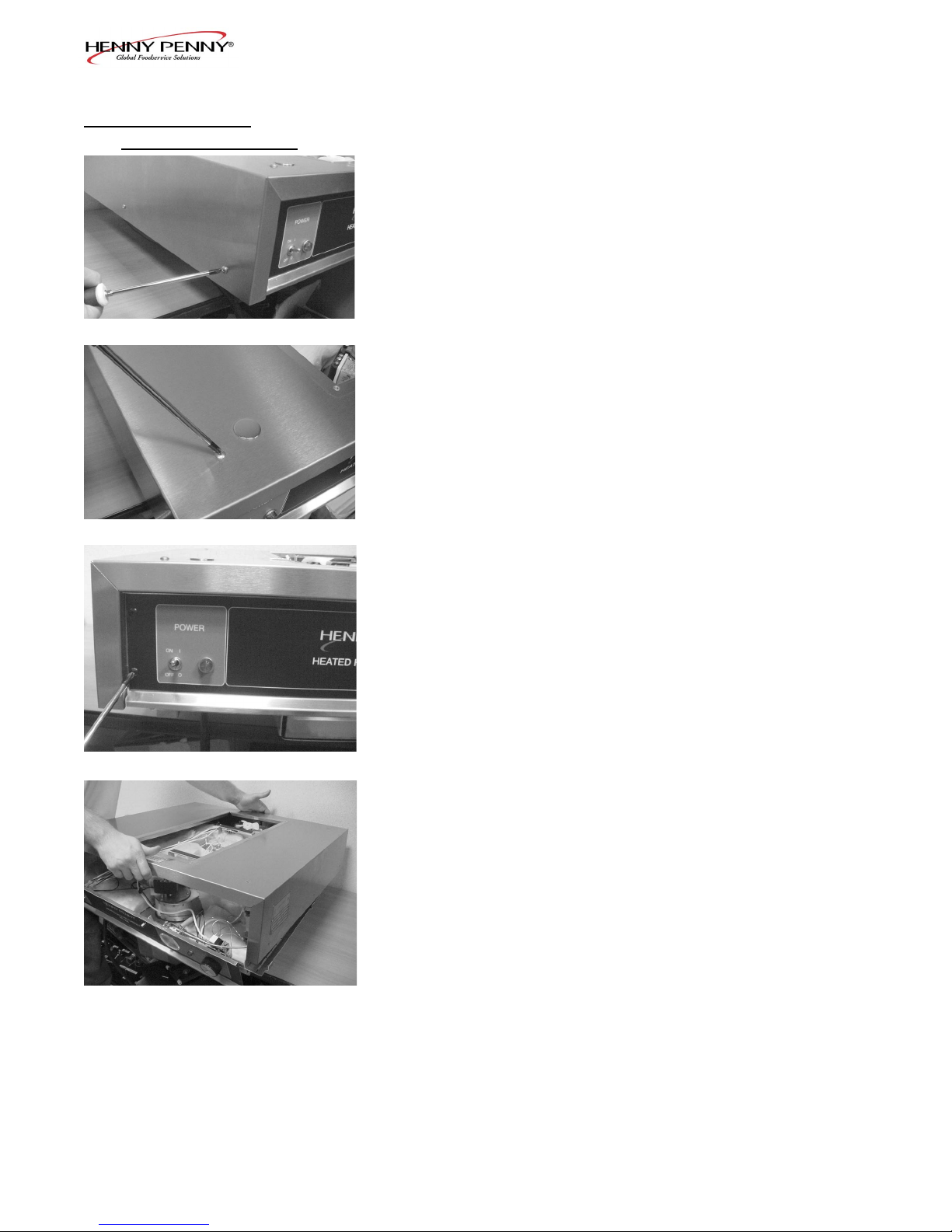
Section 2. MAINTENANCE ...................................................................................................... 2-1
2-1. Introduction...................................................................................................... 2-1
2-2. Test Instruments ............................................................................................... 2-1
2-3. Removal of Module Access Panel ................................................................... 2-1
2-4. Module Removal.............................................................................................. 2-1
2-5. Removal of Module Housing .......................................................................... 2-2
2-6. Fuse.................................................................................................................. 2-3
2-7. Power Switch ................................................................................................... 2-4
2-8. Thermostat ....................................................................................................... 2-5
2-9. Indicating Lights .............................................................................................. 2-6
2-10. Thermometer.................................................................................................... 2-7
2-11. Heater............................................................................................................... 2-8
2-12. High Limit ....................................................................................................... 2-9
2-13. Blower ............................................................................................................. 2-10
2-14. Door Gasket Replacement ............................................................................... 2-12
2-15. Wiring Diagrams ............................................................................................. 2-13
Section 3. PARTS INFORMATION........................................................................................... 3-1
3-1. Introduction...................................................................................................... 3-1
3-2. Genuine Parts................................................................................................... 3-1
3-3. How to Find Parts ............................................................................................ 3-1
3-4. How to Order ................................................................................................... 3-1
3-5. Prices................................................................................................................ 3-2
3-6. Delivery............................................................................................................ 3-2
3-7. Warranty........................................................................................................... 3-2
3-8. Recommended Spare Parts for Distributors..................................................... 3-2
106 FM06-021 i
Revised 8-21-2012


Models HHC-90X/HC-15
1-3. TROUBLESHOOTING To isolate a malfunction proceed as follows:
1. Clearlydenetheproblemorsymptomandwhenitoccurs.
2. Locate the problem in the troubleshooting table.
3. Review all possible causes, then one at a time work
through the list of corrections until the problem is solved.
If maintenance procedures are not followed correctly,
injuries and/or property damage could result.
SECTION 1. TROUBLESHOOTING
1-1. INTRODUCTION This section provides troubleshooting information in the form of
an easy to read list.
Ifaproblemoccursduringtherstoperationofanewcabinet,
recheck the Installation Section of the Operator’s Manual.
Before troubleshooting, always recheck the Operation Section of
the Operator’s Manual.
203 1-1
1-2. SAFETY Where information is of particular importance or is safety related,
the words NOTICE, CAUTION, or WARNING are used. Their
usage is described below.
SAFETY ALERT SYMBOL is used with DANGER,
WARNING, or CAUTION which indicates a personal
injury type hazard.
NOTICE is used to highlight especially important
information.
CAUTION used without the safety alert symbol indicates
a potentially hazardous situation which, if not avoided,
may result in property damage.
CAUTION used with the safety alert symbol indicates a
potentially hazardous situation which, if not avoided,
may result in minor or moderate injury.
The word WARNING is used to alert you to a
procedure, that if not performed properly, might
cause personal injury.

Models HHC-90X/HC-15
PROBLEM CAUSE CORRECTION
1-2 203
OPERATION
A. Product not • Doorsareleftopen • Keepdoorsclosedexceptto
holding load and unload product
temperature
• Thermostatsettoolow • Increasethermostatsettingbymoving
the knob to a higher number setting
• Gaskettornorworn • ReplacegasketperDoorGasket
Replacement Section
• Heaternotworking • Checkheater;replaceperHeater
Section
• Blowernotworking • Checkblower;replaceperBlower
Section
• Productheldtoolong • Holdproductonlyforrecommended
time
• Loworimpropervoltage • Usingmeter,comparereceptacle
voltage to data plate voltage
B. Cabinet • Toomuchhumidityinsidethecabinet • Emptywaterfromthewaterpan
steaming -
product • Holdingproducttoolong • Holdproductforrecommendedtime
becoming
soggy • Ventnotsetproperly(units • AdjustventperOperator’sManual
with vent adjustment only)
C. Productdry • Nowaterinpan • Removepanandputinapproximately
1” of hot water
HEATING SYSTEM
A. Unitwill • Faultythermostat • CheckthermostatperThermostat
• Faultyhighlimit • CheckhighlimitperHighLimit
Section
• Faultyheater • Checkheater;replaceperHeater
Section
• Faultywiring • Checkwiringforlooseconnections
or broken wires and repair as needed
not heat Section
1-3. TROUBLESHOOTING (Continued)

Models HHC-90X/HC-15
PROBLEM CAUSE CORRECTION
203 1-3
HEATING SYSTEM (Continued)
B. Unitwillnotheat • Faultyblower •Checkblower;replaceperBlower
to desired temp- Section
erature
• Thermometernotindicating • Checkcabinettemperaturewith
truetemperature anotherthermometer;ifnecessary,
replace per Thermometer Section
• Oneofheatersdefective • Checkheater;replaceperHeater
Section
• Doorsbeingleftopentoomuch • Onlyopendoorsasnecessary
• Gasketstornorworn • ReplacegasketperDoorGasket
Replacement Section
• Defectivehighlimitononeofheaters • Checkhighlimit;replaceperHigh
Limit Section
C. Unitoverheating • Faultythermostat • Checkthermostat;replaceper
Thermostat Section
• Faultyblower • Checkblowers;replaceperBlower
Section
VENTILATING SYSTEM
A. Bothblowers • Faultyblowers • Checkblowers;replaceperBlower
not working Section
• Faultyfuse(ifequipped) • Checkfuse;replaceperFuseSection
1-3. TROUBLESHOOTING (Continued)


Models HHC-90X/HC-15
SECTION 2. MAINTENANCE
2-1. INTRODUCTION This section provides procedures for the testing and replacement
of the various parts used within the cabinet. Before replacing any
parts, refer to the Troubleshooting Section. It will aid you in deter-
mining the cause of the malfunction.
2-3. REMOVAL OF THE
MODULE ACCESS
PANEL
In most procedures of the maintenance section, the access panel
must be removed from the top of the module. This access panel
can easily be removed by taking out the four screws that fasten it
to the module shell.
2-4. MODULE REMOVAL
If the component module of the cabinet has to be removed,
besuretoremovethefourscrews(oneateachcorner)before
lifting it from the unit. Also, when work has been completed
on the module, be sure to relocate it properly and reinstall the
screws that fasten the module to the cabinet. Failure to do so
mightcausetheunittoperforminadequately.
203 2-1
2-2. TEST INSTRUMENTS You may use two test instruments to check the electric
components.
1. A continuity light
2. An ohmmeter
When the manual refers to the circuit being closed, the continuity
light illuminates or the ohmmeter reads zero unless otherwise noted.
When the manual refers to the circuit being open, the continuity
light will not illuminate or the ohmmeter will read 1 (one) or
inniteresistance.
A continuity tester cannot be used to check coils.

Models HHC-90X/HC-15
2-5. REMOVAL OF
MODULE HOUSING
Step 2
Step 3
Step 4
Step 5
Iftheneedforextensiveserviceisrequiredonthemodulecompo-
nents, the entire outer shell of the module can be removed to make
servicing easier. To remove the outer shell of the module, follow
these procedures:
1. Remove the module from the cabinet per Module Removal
Section.
2. Removethesix(6)screwsthatarelocatedonthesidesofthe
module.
3. Removethefour(4)screwslocatedatthecornersofthe
module top.
4. Remove the screws from the control panel and the back
panel, that fasten them to the module housing.
5. Lift the shell of the module off the unit.
6. When work is completed, reassemble in reverse order.
2-2 803

Models HHC-90X/HC-15
2-6. FUSE
Allunitsarenotequippedwithfuses.
Ifbothblowersquitworkingatthesametime:
1. Remove electrical power supplied to the cabinet.
To avoid electrical shock or property damage, move the
power switch to OFF and disconnect main circuit
breaker, or unplug cord at wall receptacle.
2. Remove the cap from the fuse holder by turning it counter-
clockwise.(Locatedabovethepowercord.)
3. Pull the fuse from the holder.
4. Check the fuse for defectiveness by putting both leads of the
ohmmeter or continuity light on opposite ends of the fuse.
The fuse should be closed, or read no resistance. If the fuse
is found to be defective, replace it with a new one. Be sure to
use an identical fuse as the one being replaced.
5. Replace the cap to the fuse holder.
6. Reconnect the electrical supply to the cabinet.
203 2-3
Step 3
Step 2
Step 4

Models HHC-90X/HC-15
2-7. POWER SWITCH
Step 3
Step 4
1. Disconnect the electrical supply to the cabinet.
To avoid electrical shock or property damage, move the
power switch to OFF and disconnect main circuit
breaker, or unplug cord at wall receptacle.
2. Removethefour(4)screwsfromthecontrolpanelandpullit
down.
3. Remove all wires from the switch. Check across the two
terminals of the switch for continuity. With the switch in the
ON position, the circuit should be closed. With the switch in
the OFF position, the circuit should be open. If the switch is
found to be defective, replace it by continuing with the fol-
lowing instructions in this section.
4. Loosen the nut holding the switch on the back side of the con-
trol panel and then remove the nut on the front of the control
panel.
5. Remove the switch.
6. Install a new switch in reverse order.
7. Reconnect the wires to the switch on the same terminals that
they were previously on.
8. Push the control panel back in place and put in screws.
9. Reconnect the electrical supply to the cabinet.
2-4 803

Models HHC-90X/HC-15
2-8. THERMOSTAT
Step 5
Step 7
Step 8
Step 11
1. Disconnect the electrical supply to the cabinet.
To avoid electrical shock or property damage, move the
power switch to OFF and disconnect main circuit
breaker, or unplug cord at wall receptacle.
2. Remove the access panel from the top of the module.
3. Removethefour(4)screwsfromthecontrolpanelandpullit
down.
4. Remove the wires from the thermostat. With the thermo-
statsetatthemaximumsetting(allthewayclockwise),the
circuit should be closed. With the thermostat in the 0, or OFF,
position(allthewaycounterclockwise),thecircuitshouldbe
open. If the thermostat is found to be defective, replace it by
continuing with the following instructions in this section.
5. Removethefour(4)nutsthatholdtheblowerboxtothecabi-
net.
6. Lifttheblowerboxuptoexposethethermometerand
thermostat bulbs.
7. Whileholdingtheblowerbox,removethetwo(2)nutsthat
secure the bulb retaining clamps and remove the thermostat
bulb from the clamps.
8. Usinga5/64”Allenwrench,loosenthetwo(2)setscrewsin
the thermostat knob and remove the knob.
9. Removethetwo(2)nutsthatholdthethermostatbracketto
the control panel.
10. Removethethermostatshaftextensionwitha1/16”Allen
wrench.
11. Removethetwo(2)screwsthatholdthethermostattothe
bracket.
12. Remove the thermostat from the unit.
203 2-5

Models HHC-90X/HC-15
2-8. THERMOSTAT
(Continued)
13. Install a new thermostat in reverse order.
14. Repositiontheblowerboxandsecureitwiththefour(4)
nuts previously removed.
Be sure that both the thermometer and thermostat capillary
tubes pass through the notches in the front corners of the
blower box. Failure to do so could permanently damage the
thermometer or thermostat and cause improper operation of
the cabinet.
15. Resealthenotchesintheblowerboxcornerswithsilicone
rubber sealant.
16. Push the control panel back in place and put in screws.
17. Replace the access panel to the module.
18. Reconnect the electrical supply to the cabinet.
2-9. INDICATING LIGHTS
This section should be followed when replacing either of the
two(2)indicatinglightsinthecontrolpanel.
1. Disconnect the electrical supply to the cabinet.
To avoid electrical shock or property damage, move the
power switch to OFF and disconnect main circuit
breaker, or unplug cord at wall receptacle.
2. Removethefour(4)screwsfromthecontrolpanelandpullit
down.
3. Cut the light wires just behind the body of the light.
2-6 203

Models HHC-90X/HC-15
2-9. INDICATING LIGHTS
(Continued)
4. Removethelightbysqueezingtheretainersonthebodyand
pushing the light out through the control panel.
5. Install a new light by pushing it through the front of the con-
trol panel until it snaps securely in place.
6. Strip the ends of the cut wires and connect them to the new
light with wire nuts.
7. Push the control panel back in place and put in screws.
8. Reconnect the electrical supply to the cabinet.
2-10. THERMOMETER
Step 4
Step 6
Step 7
1. Disconnect the electrical supply to the cabinet.
To avoid electrical shock or property damage, move the
power switch to OFF and disconnect main circuit
breaker, or unplug cord at wall receptacle.
2. Remove the access panel from the top of the module.
3. Removethefour(4)screwsfromthecontrolpanelandpull
it down.
4. Removethefour(4)nutsthatholdtheblowerboxtothe
cabinet.
5. Lifttheblowerboxuptoexposethermometerandthermostat
bulbs.
6. Whileholdingtheblowerbox,removethetwonutsthat
secure the bulb retaining clamps and remove the thermometer
bulb from the clamps.
7. Removethetwo(2)nutsthatholdthemountingbrackets
on the back of the thermometer body.
8. Remove the thermometer by pulling the body and capillary
tube through the control panel.
9. Install a new thermometer in reverse order.
10. Repositiontheblowerboxandsecureitwiththefour(4)
nuts previously removed.
203 2-7
Step 4

Models HHC-90X/HC-15
2-10. THERMOMETER
(Continued)
Step 8
Be sure that both the thermometer and thermostat capillary
tubes pass through the notches in the front corners of the
blower box. Failure to do so could permanently damage the
thermometer or thermostat and cause improper operation of
the cabinet.
11. Resealthenotchesintheblowerboxcornerswithsilicone
rubber sealant.
12. Replace the access panel to the top of the module.
13. Push the control panel back in place and put in screws.
14. Reconnect the electrical supply to the cabinet.
2-11. HEATER
Step 3
Step 5
This section should be followed when replacing either of the
two(2)heatersinthecabinet.Ifthereisaheatingproblem,
both heaters should be checked.
1. Disconnect the electrical supply to the cabinet.
To avoid electrical shock or property damage, move the
power switch to OFF and disconnect main circuit
breaker, or unplug cord at wall receptacle.
2. Remove the access panel from the top of the cabinet.
3. Removethetwo(2)screwsholdingthehighlimittothe
heater.
4. Removethewiresattachedtothetwo(2)heaterterminals.
5. Removethetwo(2)screwsholdingtheheatertothemodule.
2-8 203

Models HHC-90X/HC-15
2-11. HEATER
(Continued)
Step 6
6. Remove the heater.
7. Install a new beater in reverse order.
Ifyouhavea240V,3,000Wunit,youmustinstallthenew
heater so that the coils are spread furthest apart where air
from the blower enters the heater.
8. Reattach the heater wires.
9. Refasten the high limit to the new heater.
10. Replace the access panel to the module.
11. Reconnect the electrical supply to the cabinet.
203 2-9
2-12. HIGH LIMIT
Step 5
This section should be followed when replacing either of the
two(2)highlimitsinthecabinet.Ifthereisaheatingprob-
lem in the cabinet, both high limits should be tested.
1. Disconnect the electrical supply to the cabinet.
To avoid electrical shock or property damage, move the
power switch to OFF and disconnect main circuit
breaker, or unplug cord at wall receptacle.
2. Remove the access panel from the top of the cabinet.
3. Remove the wires attached to the high limit.
4. Check across high limit terminals for continuity. As long
as cabinet temperature is below 210°F and blower has been
operating properly, high limit should be closed, or read no
resistance. If high limit is found to be defective, replace it by
continuing with the following instructions.
5. Removetwo(2)screwsthatholdhighlimittotheheater.

Models HHC-90X/HC-15
2-12. HIGH LIMIT
(Continued)
6. Remove the high limit.
7. Install a new high limit in reverse order.
8. Reconnect the two wires to the high limit.
9. Replace the access panel to the module.
10. Reconnect the electrical supply to the cabinet.
2-13. BLOWER
Step 3
Step 4
Procedures for blower motor replacement are the same on
both blowers.
1. Disconnect the electrical supply to the cabinet.
To avoid electrical shock or property damage, move the
power switch to OFF and disconnect main circuit
breaker, or unplug cord at wall receptacle.
2. Remove the access panel from the top of the cabinet.
3. Removethethree(3)screwsthatfastentheblowermotorto
the blower housing.
4. Cutthetwo(2)blowerwiresapproximately2”awayfromthe
blower.
5. Lift the blower motor and wheel out of the blower housing.
6. If replacing motor, fan, and wheel as an assembly, install new
assembly in reverse order. If replacing just the motor, con-
tinue onto step 7.
2-10 203

Models HHC-90X/HC-15
2-13. BLOWER
(Continued)
Step 7
Step 8
The blower motor can be ordered as an assembly. This will
include the motor, the fan, and the wheel. Normally, just
the motor would need replacing if found to be defective. If
you are just replacing the motor, continue with the following
procedures.
7. The fan can be pulled off the shaft of the motor.
8. With a 5/64” Allen wrench, loosen the set screw that holds
the blower wheel to the motor shaft and remove the wheel.
9. Removethefour(4)screwsthatholdtheblowercovertothe
motor.
10. Install a new blower motor in reverse order.
11. Be sure to put the spacers back between the blower cover and
the motor.
When replacing a blower motor, be sure that the motor coil is
positioned away from the heater when reinstalling.
12. Reconnect the two wires to the new blower by stripping the
wire ends and fastening with wire nuts.
13. Replace the access panel to the module.
14. Reconnect the electrical supply to the cabinet.
203 2-11

Models HHC-90X/HC-15
2-14. DOOR GASKET
REPLACEMENT
Steps 1 & 2
1. Pullthegaskettothesidetoexposethescrewsthatholdthe
retainer to the cabinet.
2. Loosen the screws around the full outside perimeter of the
gasket.
3. With the screws loose, the gasket should slide out from under
the retainer.
4. Remove the gasket and replace with a new one by reversing
the above procedures.
2-12 203
This manual suits for next models
5
Table of contents
Other Henny Penny Kitchen Appliance manuals

Henny Penny
Henny Penny TR-3 User manual

Henny Penny
Henny Penny Rotisserie Cooking User manual

Henny Penny
Henny Penny ROTISSERIE SCR-8 User manual

Henny Penny
Henny Penny MMP-941 User manual

Henny Penny
Henny Penny TR-3/6/8 User manual

Henny Penny
Henny Penny ODS 300 User manual

Henny Penny
Henny Penny ROTISSERIE SCR-6 User manual

Henny Penny
Henny Penny FlexFusion Platinum Series User manual

Henny Penny
Henny Penny 6.10 Operating instructions

Henny Penny
Henny Penny ESC-115 Electric User manual