Hickory N/7.7 G User manual
4900 Westside Avenue, North Bergen, New Jersey 07047
Tel: [201] 223-0050 Fax: [201] 223-0950
Hickory Industries, Inc.
N/7.7G Installation 10/97
Page 1 of 28
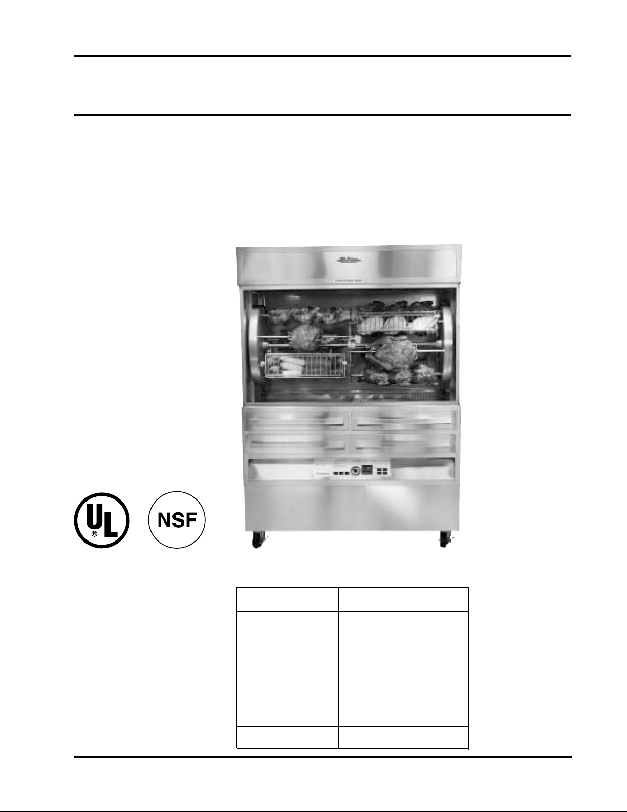
HickoryRotisseries USA
InstallationManual
Models: N/7.7G
TotalPowerRating
Burner/Spits
GasCategory
Fittings
Ignition
Delivery Date:
MachineType N/7.7 G
160,000or180,000BTU
4 or5Burnerswith 14Spits
NaturalGas,LPG
4Infra-RedGasGenerators/
1pipeburner
4 or5Electronic Ignitors
FinalInspection:

4900 Westside Avenue, North Bergen, New Jersey 07047
Tel: [201] 223-0050 Fax: [201] 223-0950
Hickory Industries, Inc.
N/7.7G Installation 10/97
Page 2 of 28
1.0Installation 3
1.1 GeneralInformation 4
1.2 DescriptionoftheDataPlate 4
1.3 MachineDimensionsininchesandmm 5
1.4 GasConversionandAdjustmentInstructions 8
1.5.1 GasConversionandAdjustmentInstructionforShowBurner(SB) 8
andWoodburningModule (WB)
1.5 VerificationforusewithNaturalGas 8
1.6 GasFlowTable(Consumption) 9
1.7.1 VolumetricMethodtoVerifytheFlameSetting,Mathematical 9
1.7 OrificeDiameters,ElectrodeGapSettings,andAirIntakeSettings 10
1.8 ChangingGasOrifices 11
1.8.1 ChangingtheGasOrifice-GasGenerators 11
1.8.2 ChangingtheGasOrifice-PipeBurnerforSBandWB 12
1.9 IgnitionCycle 13
1.9.1 AdjustingtheIgnitionElectrode 13
1.10 CheckingtheConnectedGasPressure(NominalPressure) 15
1.11 Maintenance,ResponsetoTechnicalProblems 15
1.11.1 Reasonsforproblemsandsolutions 16
1.12 SpitDriveMechanism 17
1.13 TestingorCheckingforSafety 18
1.14 DescriptionoftheElectricalConnection 18
1.15 ElectricalDiagram 19
1.16 PartsListforN/7.7G 23
1.17 ListofAdditionalPartsforN/7.7GwithShowBurner(SB) 25
1.18 ListofAdditionalPartsforN/7.7G withWoodburningModule(WB) 25
1.19 PartsListforWoodburningModule(WB) 25
TableofContents

4900 Westside Avenue, North Bergen, New Jersey 07047
Tel: [201] 223-0050 Fax: [201] 223-0950
Hickory Industries, Inc.
N/7.7G Installation 10/97
Page 3 of 28
a. Wheninstallingtheseunits,itisimportanttocomplywiththemostrecently
establishedrulesandregulationsasdeemedpertinentbythelocalandnational
electrical,gas,ventilation,sanitation,andfirecodes. Theseunitsareclassified
byUnderwritersLaboratories,Inc.asGas-FiredFoodServiceEquipmentin
accordancewithAmericanNationalStandardsInstituteANSIZ83.11b-1991,Gas
FoodServiceEquipment-RangesandUnitBoilers.
b. Thesegasunitsmustnotbedirectlyconnectedtoagasflueorexhaust. However,the
unitsmayonlybeoperatedinconjuctionwithacanopytypeexhausthood.
c. Theroomwheretheunitsarebeinginstalledmustbeventilatedinaccordanceto
thevalidcodesandregulations.
d. Theunitsaretobeinstalledsecurelyandhorizontally. Theunitsmaybe
installedoncombustiblefloors. Theunitsmaybeinstalledonadjustablelegsoron
casters(wheels).
e. Theminimumclearancetotherearorsidewallsmustbe3inches. Itisalso
importanttoinsurethatthebottomoftheunitsiskeptclearsothat properventilation
orairexchangecanoccur.
f. Normally,theunitswillbesenttotheoperatoralreadysetupfortheparticular
typeofgasavailableattheirlocation. However,unlessotherwisespecified,the
unitswillbesetupfornaturalgasuse. Beforeinstallingandusingtheunitsforthe
firsttime,itisimportanttomakesurethatthegastypeandpressureindicatedonthe
dataplatematchesthetypeofgasavailableinthelocation. Shouldthisnotbethe
case,itisimperativetochangeorconverttheunitstotheneededgastype.
g. Theunitsmustbefittedwiththemanualshut-offgascock(valve)suppliedwiththe
machine. Thismanualvalveisneededtoshutoffthegastothemachineduring
maintenancework,repairs,andiftheunitneedstobedisconnectedforanyreason.
h. Agasregulatorisalsosuppliedwiththemachine. Thiscomponentisneededsothat
theappropriategaspressurecanbesetandinsureanoptimumoperationoftheunit.
i. Dependingonlocalcodesorifdeemednecessary,agasfiltermayalsoberequired.
1.0 InstallationInstructions

4900 Westside Avenue, North Bergen, New Jersey 07047
Tel: [201] 223-0050 Fax: [201] 223-0950
Hickory Industries, Inc.
N/7.7G Installation 10/97
Page 4 of 28
1.1 GeneralInformation
TheOperatingInstructionsaretobegiventotheoperatoroftherotisserie. Allunit
operatorsaretobefamiliarwiththefunctionsoftherotisserie.
TheOperatingInstructionsshouldbekeptinalocationclosetotherotisserie. Itshouldbe
easilyrecognizeableandeasilyaccessible.
Theserotisseriescanbeusedwithboth naturalandLPGgases. Therotisseriescanbe
convertedoradjustedtoanytypeofthelocallydistributednaturalandLPGgases.
Itisrecommendedthatarepairandmaintenancecontractbesignedwiththe
manufacturer'sagent,distributor,orserviceagency.
1.2 DescriptionoftheDataPlate
WARNING!
Thisunitmustbeinstalledandconnectedinaccordancetothelatestregulations
andcanonlybeoperatedinconjunctionwithforcedventilationorexhausthood.
Thisunithasbeendesignedforprofessionaluseonly
andmayonlybeinstalledorrepairedbylicensedserviceagencies!
Beforeinstallingorusingthisequipment,readtheseinstructions!
HICKORY INDUSTRIES, INC.
COMMERCIAL COOKING APPLIANCES
NORTH BERGEN, NJ 07047
MODEL N/7.7 G SERIAL NO.
MOTOR: 110 - 115 VOLTS 60 CYCLE AC CURRENT
1/2 HP SINGLE PHASE 5.7 RPM
BURNERS 4 / 1
GASINPUTPERBURNER BTU/H
MANIFOLDPRESSURE
TYPEOF GAS
MFG.DATE
40,000/20,000
5.5"
NAT
MINIMUM INSTALLATION CLEARANCE
SIDE: 6INCHES
BACK: 6 INCHES
MAXIMUM LAMP WATTAGE: 150 WATTS
FOR INSTALLATION ON A COMBUSTIBLE FLOOR
Gas-firedFood ServiceEquipmentClassified by
UnderwritersLaboratories Inc. In accordancewithAmerican
NationalStandards InstituteANSIZ 83.11b-1991,GasFood
ServiceEquipment-Ranges andUnitBoilers
LISTED
69D6
HICKORY INDUSTRIES, INC.
COMMERCIAL COOKING APPLIANCES
NORTH BERGEN, NJ 07047
MODEL N/7.7 G SERIAL NO.
MOTOR: 110 - 115 VOLTS 60 CYCLE AC CURRENT
1/2 HP SINGLE PHASE 5.7 RPM
BURNERS 4 / 1
GASINPUTPERBURNER BTU/H
MANIFOLDPRESSURE
TYPEOF GAS
MFG.DATE
11"
LPG
MINIMUM INSTALLATION CLEARANCE
SIDE: 6INCHES
BACK: 6 INCHES
MAXIMUM LAMP WATTAGE: 150 WATTS
FOR INSTALLATION ON A COMBUSTIBLE FLOOR
Gas-firedFood ServiceEquipmentClassified by
UnderwritersLaboratories Inc. In accordancewithAmerican
NationalStandards InstituteANSIZ 83.11b-1991,GasFood
ServiceEquipment-Ranges andUnitBoilers
LISTED
69D6
40,000/20,000

4900 Westside Avenue, North Bergen, New Jersey 07047
Tel: [201] 223-0050 Fax: [201] 223-0950
Hickory Industries, Inc.
N/7.7G Installation 10/97
Page 5 of 28
1.3 MachineDrawingsandDimensions
ThefollowingdrawingoftheFrontView,SideView,andTopViewindicatewherethe
dimensionsaretakenandshouldbeusedtoplantheinstallationoftheunits.
N/7.7 G inches[mm]

4900 Westside Avenue, North Bergen, New Jersey 07047
Tel: [201] 223-0050 Fax: [201] 223-0950
Hickory Industries, Inc.
N/7.7G Installation 10/97
Page 6 of 28
7.7GwithShow Burner inches[mm]

4900 Westside Avenue, North Bergen, New Jersey 07047
Tel: [201] 223-0050 Fax: [201] 223-0950
Hickory Industries, Inc.
N/7.7G Installation 10/97
Page 7 of 28
N/7.7Gwithseparatehearthburner inches[mm]

4900 Westside Avenue, North Bergen, New Jersey 07047
Tel: [201] 223-0050 Fax: [201] 223-0950
Hickory Industries, Inc.
N/7.7G Installation 10/97
Page 8 of 28
1.4 GasConversionandAdjustmentInstructions
Beforeconvertingoradjustingthemachinetoanothertypeofgas,itisimperativethatthe
manualgascockbeturnedtothe"off"position. Theelectricalpowertothemachinesshould
alsobeturnedoff. Whenconvertingthegasgeneratorsforusefromonetypeofgasuseto
another,thegasorifice(orinjector)mustbechangedaccordingtothetableonpage9. In
addition,thespringinthepressureregulatorsuppliedwiththeunitmustbechangedsothatit
canoperateatothergaspressures. SpringsfortheregulatorcanbeorderedfromHickory
Industries.
1.4.1 GasConversionandAdjustmentInstructionsforShowBurner(SB) and
WoodburningModule(WB)
Beforeconvertingoradjustingthemachine,itisimperativethatthemanualgascockbe
turnedtothe"off"position. Theelectricalpowertothemachinesshouldalsobeturnedoff.
Whenconvertingfromonetypeofgastoanother,thegasorifice(orinjector)andthe
primaryairadjustmentmustbechangedaccordingtothetableonpage9. Inaddition,the
springinthepressureregulatormustbechangedaspreviouslyexplained.
1.5 VerificationforusewithNaturalGas
Theflamesettingforeachgasgeneratorandforthepipeburnercanbeconfirmedbyusing
thevolumetricmethodinconjunctionwiththemaingasmeter. Eachburnerhasan
independentsolenoidgasvalve. Eachvalveiscontrolledbyitsown,independentGaslite
sparkignitionmodule. Theamountofgasflowingthroughthevalvescannotbeadjusted
manually;thereisonlyan"on"or"off"position.
Tocarryoutthisverificationprocedure,itisnecessarytoobtaintheheatingvalue(BTU/ft3)
ofthelocalgasfromthelocalgascompany. Avariationintheheatingvalueofthelocal
gasfromthat onthetable(1.6)willresultinavariationofthepoweroutputoftheunit!
Ifthemeasuredgasvolumedoesnotcorrespondtothevaluesinthefollowingtable(1.6),the
itemswhichshouldbecheckedare:
A. Theincoming(connected)gaspressurewhileallburnersandallotherappliances
inthelocationareoperational.
B. Ifthegaspressureiscorrect,itmustbeverifiedthatthepropersizegasorificesarein
place(seepage9).
Solenoid Valve

4900 Westside Avenue, North Bergen, New Jersey 07047
Tel: [201] 223-0050 Fax: [201] 223-0950
Hickory Industries, Inc.
N/7.7G Installation 10/97
Page 9 of 28
1.6.1 VolumetricMethodtoVerifytheFlameSetting,Mathematical
WARNING! Noothergasequipmentcanbeinoperationduringthisprocedure.
CalculationofflowrateEinft3/hour
Q= E
Hi
Q= Flow rateinft3/time
E= HighFlamePowersettinginBTU/hr
Hi= HeatingvalueinBTU/ft3
Thus,fornaturalgas:
Q=40,000 BTU/hr = 38.50ft3/hr = 0.64ft3/min.
1040 BTU/ft3
Q= 0.64ft3/min.
Calculationofthenaturalgasneededin1hourbya7.7G(4burners)atfullpower:
Q=38.50 *4 = 154ft3/hr = 2.56ft3/min.
Thetimeandtheflowmeasurementsshouldbetakenatthegas(flow)meterwitha
chronometer(stopwatch).
Torunthetest,openthemanualgascockvalve,startuptheunitaccordingtothestart-up
instructions.
Allowtheunittopre-heat(burn)for10to15minutes. Verifythattheflowrateiscalibrated
totheappropriateflowrateindicatedinthetable.
NOTE: Thismathematicalcalculationwasdoneassuminga#38orificesizeandaconnected
gaspressureof5.5"withaninfra-redgenerator. Theactualflowratewillvary
dependingontheHeatingValueofthelocalgasandonthesetgaspressure!
1.6 GasFlowTable(Consumption)
in ft3/hr
Gas Flow
per Burner (40,000 BTU)
BTU/ft³
Heating Value in
Gas
HighFlameSetting
Natural
Propane
Butane
1040 38.50
2500
2500 16.00
16.00

4900 Westside Avenue, North Bergen, New Jersey 07047
Tel: [201] 223-0050 Fax: [201] 223-0950
Hickory Industries, Inc.
N/7.7G Installation 10/97
Page 10 of 28
Gas/Pressure OrificeSize PrimaryAirIntake
TypeN/7.7Gwith ShowBurnerorWoodburningModule
TypeN/7.7 G
1.7 OrificeDiameters,ElectrodeGapSettings,andAirIntakeSettings
Gas/Pressure OrificeSize
Øindrill size
Natural/5.5"
inchesW.C.
Butane/11"
#38
#51
inchesW.C. Øindrill size ininches
Natural/5.5" #40
ElectronicIgnition
ElectrodeGap
ElectronicIgnition
1/8"Betweenrods
1/8"Betweenrods
andBurnersurface
1/8"Betweenrods
1/8"Betweenrods
andBurnersurface
1/8"Betweenrod
andPipeBurner 1/8"
Propane/11" #51 1/8"Betweenrods
1/8"Betweenrods
andBurnersurface
Propane/11" #55
Propane/11" #55
1/8"
1/8"
1/8"Betweenrod
andPipeBurner
1/8"Betweenrod
andPipeBurner

4900 Westside Avenue, North Bergen, New Jersey 07047
Tel: [201] 223-0050 Fax: [201] 223-0950
Hickory Industries, Inc.
N/7.7G Installation 10/97
Page 11 of 28
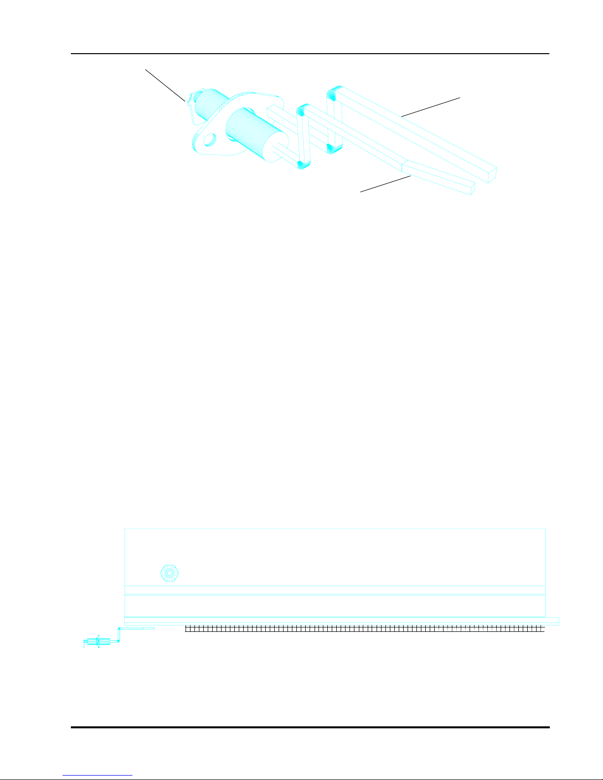
1.8 ChangingGasOrifices
1.8.1 ChangingtheGasOrifice-GasGenerators
The7.7Gasunithasfourinfra-redgasgenerators. Inoldermodels,thesegeneratorsused
ceramicradiatingplates. Allnew7.7unitsuseInconel(Metalalloy)radiatingplates. All
fourburnersareinterchangeablewithaminorburnerinletpipepositionmodification.
1. Whenlookingfromtheverytopoftherotisseriedownward,youwillseethe
following:
Gas Inlet Pipe
Alternate Opening for
Inlet Pipe (plugged) Burner
Orifice
Venturi
Top View Gas Generator
2. The burner orifice can be removed and replaced using a 7/16" wrench. The orifice
must be sealed and tightly in place.

4900 Westside Avenue, North Bergen, New Jersey 07047
Tel: [201] 223-0050 Fax: [201] 223-0950
Hickory Industries, Inc.
N/7.7G Installation 10/97
Page 12 of 28
AirIntakeAdjustment
LockNut
MainOrifice
VenturiTube
VenturiAssembly
1.8.2 ChangingtheGas Orifice-PipeBurnerforSBandWB
1. Removethelefthanddrippanandloadingtray.
2. Unscrewandremovethemetalcovertoexposetheventuri.
3. Theventuritubeisontheinletsidetothepipeburner.
4. Ontheventuri,loosenthelocknuts(7/8"wrench)andthenmovethenut
andtheairintakecapallthewaytothetopofthenipple.
5. Witha3/4"wrench,loosenthenipplesothatitcanberemovedfromthe
venturi.
6. Withthenipple/orificeassemblyoff,separatethemainorificefromthe
nipplewithapipewrenchorapairofpliers.
AirIntakeCap
Nipple
Re-assembleallofthecomponentswiththeneworifice. Makesurethattheproperairintake
adjustmentismadeforthenewtypeofgas(accordingtothetableonpage9). Theflamesshouldbe
blueincolor,mustbestable,andmustnot"liftoff"theburner.

4900 Westside Avenue, North Bergen, New Jersey 07047
Tel: [201] 223-0050 Fax: [201] 223-0950
Hickory Industries, Inc.
N/7.7G Installation 10/97
Page 13 of 28
1.9 IgnitionCycle
Inordertostartthecookingcycle,theburnersmustbeignited. Theignitioncyclewillstart
onlywhenthefollowingprocedureisfollowed:
a. The"HEAT"switchisturnedto"on".
b. Theindividualburnerswitchesareturnedto"on".
NOTE: TheSBandWBpipeorrearburnerscanbeshutoffusingan
unmarkedtoggleswitchlocatedontheuppersideofthe
controlpanel. Makesurethatthisisinthedesiredposition.
c. Acookingtemperaturemustbesetonthethermostat(i.e.450°F).
d. Thecookingtimermustbeactivated(seeOperatingInstructions).
Oncethesestepsarecompleted,theunitwillcallforheatandtheignitioncyclewillbe
activated. Theignitionsystemwillcausesparkingontheignitionelectrode. Oncethe
burnerislitbythespark,theflameoftheburnerwillheatthesensingprongontheignition
electrodesendingasignalbacktotheignitionmodule. Thissignalindicatesthatasparkis
nolongerneededandthatthesolenoidgasvalvemuststayopen. Whenthecooking
temperatureisreached,assensedbythethermocoupleattachedtothethermostat,the
electricalpowertotheignitionmoduleswillbecutoff,shuttingdowntheignitionmodule
andtheburners. Whenthetemperaturedropsbelowthesetpoint,electricalpowerissentto
theignitionsystemonceagain,thusstartingtheignitioncycleallover. Thesystemwill
cycleonandoffasneededtomaintainthesetcookingpoint.
Theignitionmoduleswillattempttoignitetheircorrespondingburnersthreetimes. Ifthe
burnersfailtolightafterthreetries,themodulewilllock-out,shuttingdownallgasflowand
furthersparking.
Inordertostarttheignitioncycleafteralock-out,theheatswitchesandindividualburner
switchesmustbeturned"off"and"on"again. Thismayhavetobedoneseveraltimeswhen
startinguptheunitforthefirsttimeduetoairinthegaslines.
1.9.1 AdjustingtheIgnitionElectrode
Theignitionelectrodesareadjustedforanoptimumignitioncyclebeforetheunitleavesthe
factory. Ifforsomereasontheelectrodesneedadjusting(i.e.ifonetakesahitwithaspit),it
canbedoneasfollows.
1. Toreachtheignitionelectrode,opentheslidingglassdoorsandremoveallspits.
2. Eachelectrodeisattachedtothemainbodyofthemachinewithan8/32"screwand
nut. Itisimportantthatthisscrewmakesolidmetaltometalcontactbetweenthe
electrodecasingandthebodyoftherotisserie. Thismetaltometalcontactiswhat
actsasagroundingconductorforthegroundingprongontheignitionelectrode.
3. Duringtheignitionprocess,asolidblue/yellowsparkshouldtravelbetweenthetipof
thetwoelectrodeprongs.
4900 Westside Avenue, North Bergen, New Jersey 07047
Tel: [201] 223-0050 Fax: [201] 223-0950
Hickory Industries, Inc.
N/7.7G Installation 10/97
Page 14 of 28
IgnitionElectrode
Grounding Prong
Ignition / Sensing Prong
Ignition Wire Connection
4. Makesurethatthedistancesbetweentheprongsandthesurfaceoftheburnerare
about1/8".
5. Ifthedistancesbetweentheprongsand/ortheburnersurfacearetoogreat,theunit
maysparkbutnotignitetheburner.
6. Ifthedistancebetweentheprongsandtheburnersurfacearetooclose,contactmay
occurcausingashort-circuitandpreventinganyignition. NotethattheINCOLOY
(metal)surfaceoftheburnerswillwarpdownwardoncetheburnerheatsup. Ifthis
happensandthesurfacedoes makecontactwiththeelectrodeprongs,theburnerwill
shutoff.
7. Whenadjustingtheprongs,makesuretosupportthebaseoftheprongwithonepair
ofpliersandadjustthetipoftheprongwithanotherpair. Thiswillpreventbreakage
oftheceramic casingofthesensingprong. Iftheceramiccasingdoesbreak,itwill
causeerraticignitionproblemsandtheelectrodewillhavetobereplaced.
IgnitionElectrodePosition

4900 Westside Avenue, North Bergen, New Jersey 07047
Tel: [201] 223-0050 Fax: [201] 223-0950
Hickory Industries, Inc.
N/7.7G Installation 10/97
Page 15 of 28
1.10 CheckingtheConnectedGasPressure(NominalPressure)
Closethegascockwherethegaslineisconnectedtothemachineandattachamanometer
tothetap(allenscrew)onthegascock. Withthemanometerconnected,openthegas
cockandigniteallburners. Alongwithallothergasappliancesatthelocationin
operation,measurethegaspressure.
Thisidealoperatingpressureshouldbe5.5"W.C.fornaturalgasand11"W.C.forLPG.
Ifthepressureistoohighandcannotbeadjusteddownward,checktoseeiftheproper
adjustingspringisintheregulator. Ifthisiscorrect,theregulatormembranemayhavebeen
rupturedbyexcessivegaspressureandmayhavetobereplaced. Donotoperatetherotisserie
ifthegaspressureexceedstheidealvalues.
Iftheoperatingpressureisbelow5.5"W.C.fornaturalgasorbelow11"W.C.forLPG,the
unitshouldnotbeoperated. Thepressureshouldbeadjustedtotheidealsettingusingthe
pressureregulatingscrewonthepressureregulator.
Ifthepressureistoolowandcannotbeadjustedupward,alsochecktheregulator. Ifthisis
operatingproperly,verifythepressurecomingoutofthemaingasmeter. Anothertypical
sourceofthispressureproblemisthatthegasline(pipe)diameterleadinguptotheunitis
toosmall. Ifthegaslineisunder-sized,theappropriatepressuremaynotbereached. Donot
operatetheunitifthepressurefallsbelowtheidealvalues.
Ifthemeasuredpressureisstillbelowtheidealrangeanditisnotpossibletoresolvethe
problem,thelocalgascompanyorgassuppliershouldbecontactedsothattheycanresolve
theproblem.
Afterthepressurehasbeenset,closethegascockonceagain,removethemanometer,seal
thegastap,andthenre-openthegascock.
WARNING: Afteraninstallation,repairs,ormaintenance,makesurethatthereare
nogasleaksanywhereinthegaslinesorsystem.
1.11 Maintenance,ResponsetoTechnicalProblems.
Shouldatechnicalproblemariseforanyreason,shutoffthemachineandcallfortechnical
service.
Aroutinemaintenanceshouldbecarriedoutatleastonceayear. Contactyourlocal,
certifiedservicecompanyformaintenance.

4900 Westside Avenue, North Bergen, New Jersey 07047
Tel: [201] 223-0050 Fax: [201] 223-0950
Hickory Industries, Inc.
N/7.7G Installation 10/97
Page 16 of 28
Solution
a. MakesurethattheTEMPERATURE
switch,theindividualburnerswitches
areon. Thermostatmustbeset(i.e.
550°F)andtimermustbeoperational
(cookcycle).
b. Makesurethatthethreepronged
plugsuppliedwiththeunitisbeing
used,thatthepolarityiscorrect,and
therotisserieisproperlygrounded.
a. Adjustelectrodetipsto1/8"apart.
b. Ifthemachineisused,fatmayhave
carbonizedontheelectrodetipsorrust
mayhaveappeared. Thisprevents
propersparking. Sandandclean
metalrods.
c. Makesurethatelectrodeisproperly
fastenedandmakessolidcontactwith
therotisseriebody.
d. Makesurethattheignitionwireis
properlyfastenedtotheignition
moduleandtotheelectrode.
e. Checktheignitionwireforbreaches
whichmaycausesparkingtooccur
betweenthecableandthebodyof
rotisserie. Repaircableatbreach.
f. Checkelectricalinputtomodule.
Modulemayneedtobereplaced.
a. Turnallmanualgasvalvesto"on".
Makesureallsolenoidvalvesopen.
b. Makesurethatthehot,neutral,and
groundleadsareproperlymatchedup.
Ifneutralandhotareswitched,the
"flameon"signalwillnotreach
ignitionmodule,lockingoutgas.
c. Checktheoperatinggaspressure.
a. Adjustthetipsoftheelectroderods
sothattheyareabout1/8"fromthe
burnersurface. Makesurenocontact
occursbetweentherodsandburner.
a. Switchexhausthoodtoonbefore
ignitingtheunit. Alsoopenoneofthe
slidingglassdoors.
b. Re-adjustignitionprongs.
Problem
Allelectrodes
donotspark.
Oneelectrode
doesnotspark.
Allelectrodesspark,
noburnerlights.
Anelectrodesparks,
flamedoesnotlight.
Burnerignitesfor5
to10secondand
thengoesoff,espe-
ciallyinthemorning
whencold
Cause
a. Burnersnot"on".
b. Electricalsystemnot
groundedproperly.
a. Electrodetipstoofarapart.
b. Electrodetipsaredirtyor
carbonized.
c. Electrodenotgrounded.
d. Ingnitionwireloose.
e. Ignitionwirenotproperly
insulated.
f. Ignitionmodulefaulty.
a. Checkallgasflow.
b. Checkpolarityonthe
electricalconnections.
c. Flameistooweak.Not
enoughgasflow.
a. Electrodetipsaretoofar
fromburner.
a. Highhumidityevironment.
suchascausedbyleaving
waterindrippan
overnight.
b. Unitnotproperlyadjusted
tonewconditions.
1.11.1 Reasonsforproblemsandsolutions
4900 Westside Avenue, North Bergen, New Jersey 07047
Tel: [201] 223-0050 Fax: [201] 223-0950
Hickory Industries, Inc.
N/7.7G Installation 10/97
Page 17 of 28
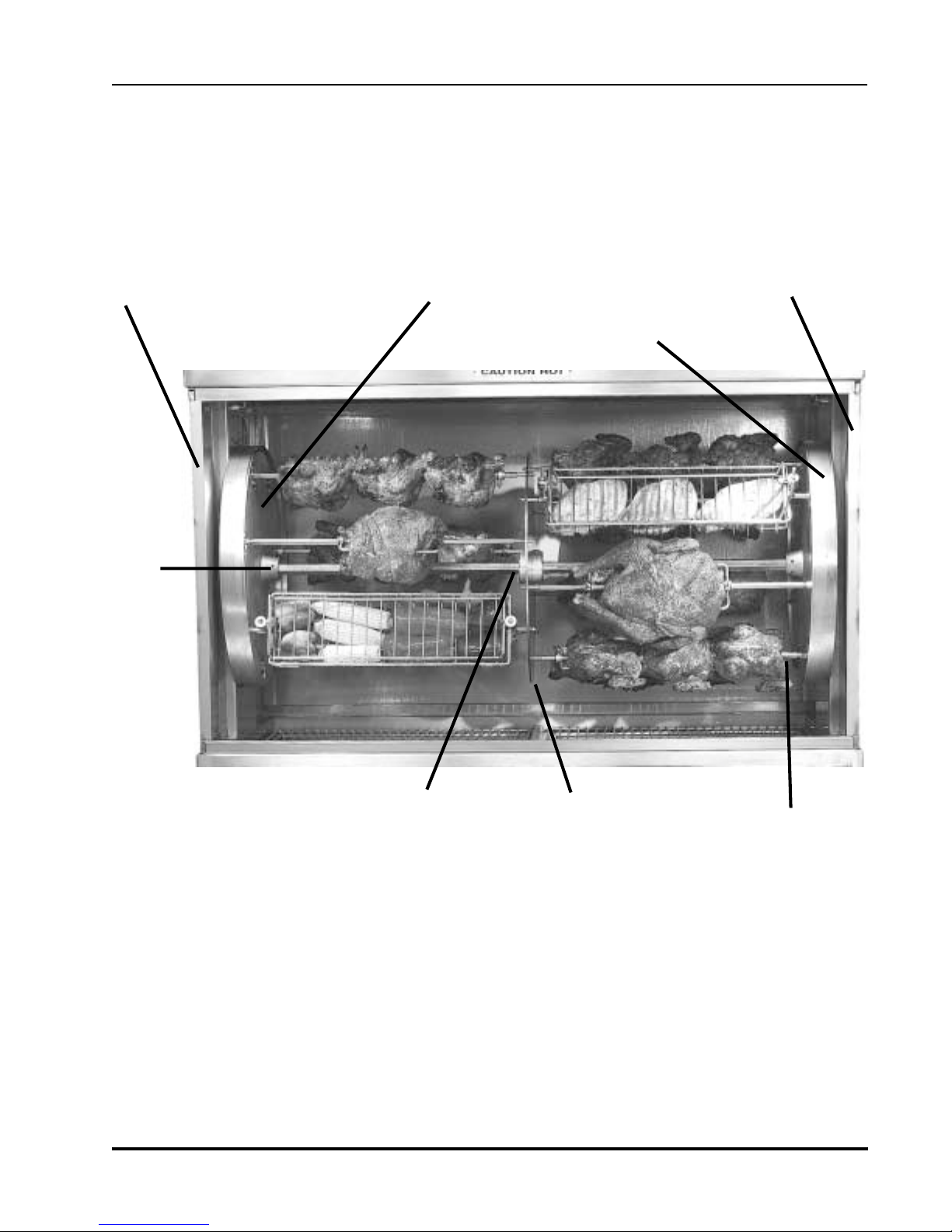
1.12 Spit Drive Mechanism
This unit is equipped with a planetary motion spit drive system. This means that each spit is
turning upon its axis at the same time that they turn about the center shaft. When the motor
switch is turned to on, the disks and the spits will begin to turn. Insure that the mechanism
turns smoothly when testing the unit.
Center Shaft Spit
Set
Screws
Removable Side Panels Removable Side Panels
Before cooking, it is imperative that the center shaft and the set screws be covered and protected
with aluminum foil. This will prevent fats from carbonizing on the shaft, making the removal of the
aluminum disks much easier in the future. If the screws and shaft are not protected, eventually it
may be impossible remove them should there be a problem in the spit drive mechanism.
The driven and the stationary drive gears are located behind the aluminum disks. These can be
viewed by taking out the removable side panels (there are four removable panels). The driven gears
and the stationary gear should be viewed once a week to check for fat or carbonization build-up.
Any fat or dirt should be cleaned off since a build-up will eventually damage the drive system.
In order to access the entire drive system, loosen the set screws fastening the aluminum disks to the
center shaft. Once loose, the disks can be slid along the center shaft toward the steel slave disk in
the center.
Center Disk Slave
Aluminum Disk
Aluminum Disk Cover

4900 Westside Avenue, North Bergen, New Jersey 07047
Tel: [201] 223-0050 Fax: [201] 223-0950
Hickory Industries, Inc.
N/7.7G Installation 10/97
Page 18 of 28
NOTE: If fat or carbon have built up on the set screws or on the center shaft, it may not
be possible to move the alumium disks!
With the disks away from the sides, all components of the drive mechanism should be
thoroughly cleaned. This will guarantee that the drive mechanism works smoothly.
Even though the aluminum disks are protected with stainless steel covers, fat will eventually
build up on the gears. If this fat is not cleaned, it will eventually carbonize. When the
carbon build-up is serious enough, the drive mechanism will jam and it will need
to be replaced.
When replacing the disks, a slight dab of FDA (food safe) approved gease should be added
to all gears.
Finally, when inserting spits, make sure to stop the motor! This unit is supplied with a
foot switch which will stop the drive mechanism, allowing the operator to insert the
spits easily! If spits are inserted without stopping the motor, there is a chance that the drive
system will be jammed and cause severe damage.
1.13 TestingorCheckingforSafety
Afteraconversion,anewinstallation,orafterarepair,itisimportantthattheunitbe
testedtoinsurethatitoperatesproperly. Thisshouldincludethefollowing:
Testthegassystemforgasleaks.
Checkthattheunithasenoughclearancebehindandtothesides.
Checkthatenoughprimaryandsecondaryairisavailable(strongblueflameonthepipe
burner,brightorangegasgenerators).
Checkforpotentiallyflammableobjectsorpotentialflammabilityproblems.
Checkforproperventilationandexhaust.
Checkforproperroomventilation.
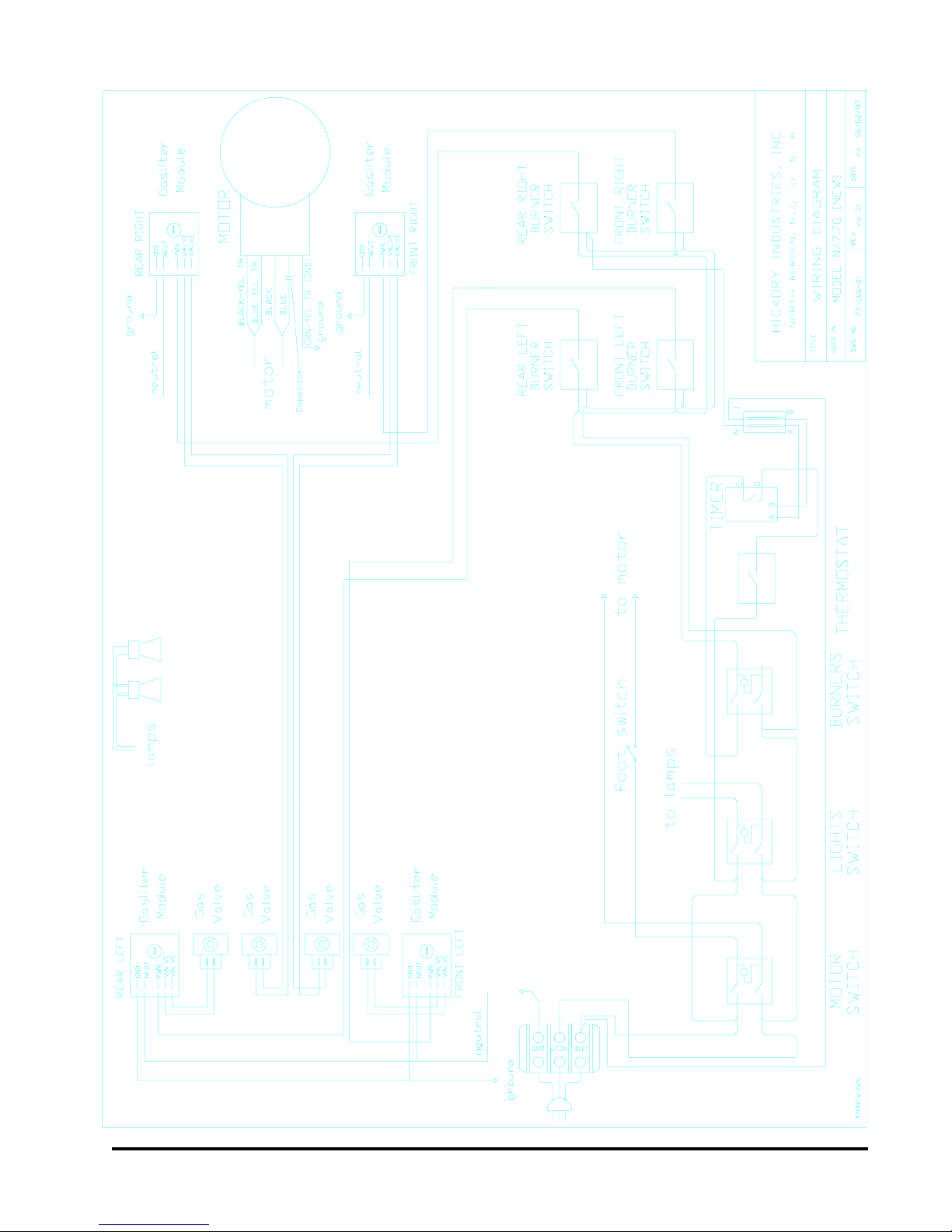
1.14 DescriptionoftheElectricalConnection
Theelectricalconnectionsaretobemadeinaccordancetolocalandnationalcodes.
Allgasmachinesoperatewith120Volt,singlephase,60Hz. ANEMA5-15Pplug
issuppliedwiththeunits.
Allpertinentelectricalinformationcanbetakenfromtheelectricaldiagram.
NOTE: Properpolarityintheelectricalsystemisneededforproper
operationofthegassystem!

4900 Westside Avenue, North Bergen, New Jersey 07047
Tel: [201] 223-0050 Fax: [201] 223-0950
Hickory Industries, Inc.
N/7.7G Installation 10/97
Page 19 of 28
1.15 ElectricalDiagram
4900 Westside Avenue, North Bergen, New Jersey 07047
Tel: [201] 223-0050 Fax: [201] 223-0950
Hickory Industries, Inc.
N/7.7G Installation 10/97
Page 20 of 28
Table of contents
Other Hickory Kitchen Appliance manuals


