HID Aero X100 User manual

© 2019 - 2020 HID Global Corporation/ASSA ABLOY AB. All rights reserved. HID, the HID Brick logo, the Chain Design, HID Aero, and HID Signo are trademarks or registered
trademarks of HID Global, ASSA ABLOY AB, or its aliate(s) in the US and other countries and may not be used without permission. All other trademarks, service marks, and
product or service names are trademarks or registered trademarks of their respective owners.
hidglobal.com An ASSA ABLOY Group brand
HID Aero™ X100
Reader Interface
Up to 4 Readers, 7 Inputs, 4 Outputs PLT-04234, Rev. A.3
INSTALLATION GUIDE
X100 Overview
The X100 has two reader ports, four relays, seven inputs, and one RS-485 port for IO module connection.
Supplied parts
HID Aero X100 reader interface (1)
Installation guide (1)
Mounting screws (4) 0.138" × 1" (3.5 mm × 25 mm)
Recommended parts
(not supplied)
Certified DC power supply
Drill with various bits for mounting hardware
For DIN rail mounting: Brackets (2) - Phoenix Contact,
USA 10 Series Rail Adapter, part number 1201578.
Screws (4) - Self tapping, countersunk,
3.0 mm × 10 mm (or 3.0 mm × 8 mm)
CABLE REQUIREMENTS (NOT SUPPLIED)
Readers - OSDP
4 conductor twisted pair over-all
shield, Belden 3107A or equivalent.
2000 ft (610 m) maximum. Utilize one
pair for data and one pair for power
Readers -
Wiegand / C&D
4-conductor, 18 AWG, shielded, 500 ft
(150 m) maximum
IO Module
One twisted pair, shielded, 24 AWG,
120Ωimpedance, 4,000 ft
(1,219 m) maximum
Alarm Inputs
One twisted pair per input,
30Ωmaximum, typically 22 AWG,
1000 ft (304.8 m)
Power and Relays 2-conductor shielded
18 to 16 AWG, 500 ft (150 m)
4.53"
(115 mm)
5.51"
(140 mm)
RELAYS 1-4
See step 5.
INPUTS 1-4
See step 4.
INPUTS 1-4
See step 4.
READERS 1-2
See step 3.
Status LEDs
See page 6
POWER, TAMPER, AC FAIL, BATT FAIL
See step 7.
Status LEDs
See page 6
RELAYS 1-4
See step 5.
READERS 1-2
See step 3.
DIP SWITCH
See step 6.
JUMPERS
See step 2. IO MODULE PORT
See step 2.
HID Aero™ X100 Installation Guide
PLT-04234, Rev. A.32
Powering
Trusted Identities
RS-485
termination jumper
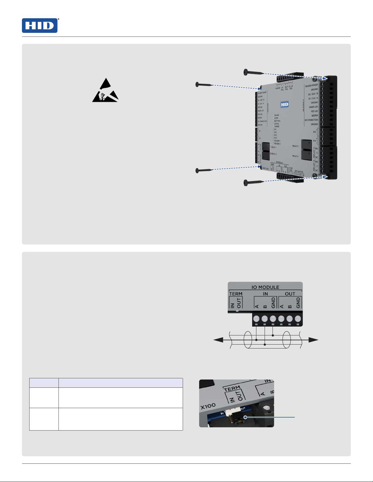
ATTENTION
Observe precautions for handling
ELECTROSTATIC SENSITIVE DEVICES
Always mount the controllers and interface panels in
a secure area.
Mount using the supplied screws 0.138" × 1"
(3.5 mm × 25 mm).
Alternatively mount on a DIN rail using compatible
DIN rail mounting brackets and screws.
See Recommended parts.
Note: The side terminal connectors must be
removed to fit the mounting brackets.
Port 1 to serial IO devices Port 2 to serial IO devices
To other
devices
on the bus
To other
devices
on the bus
1. Mounting the X100
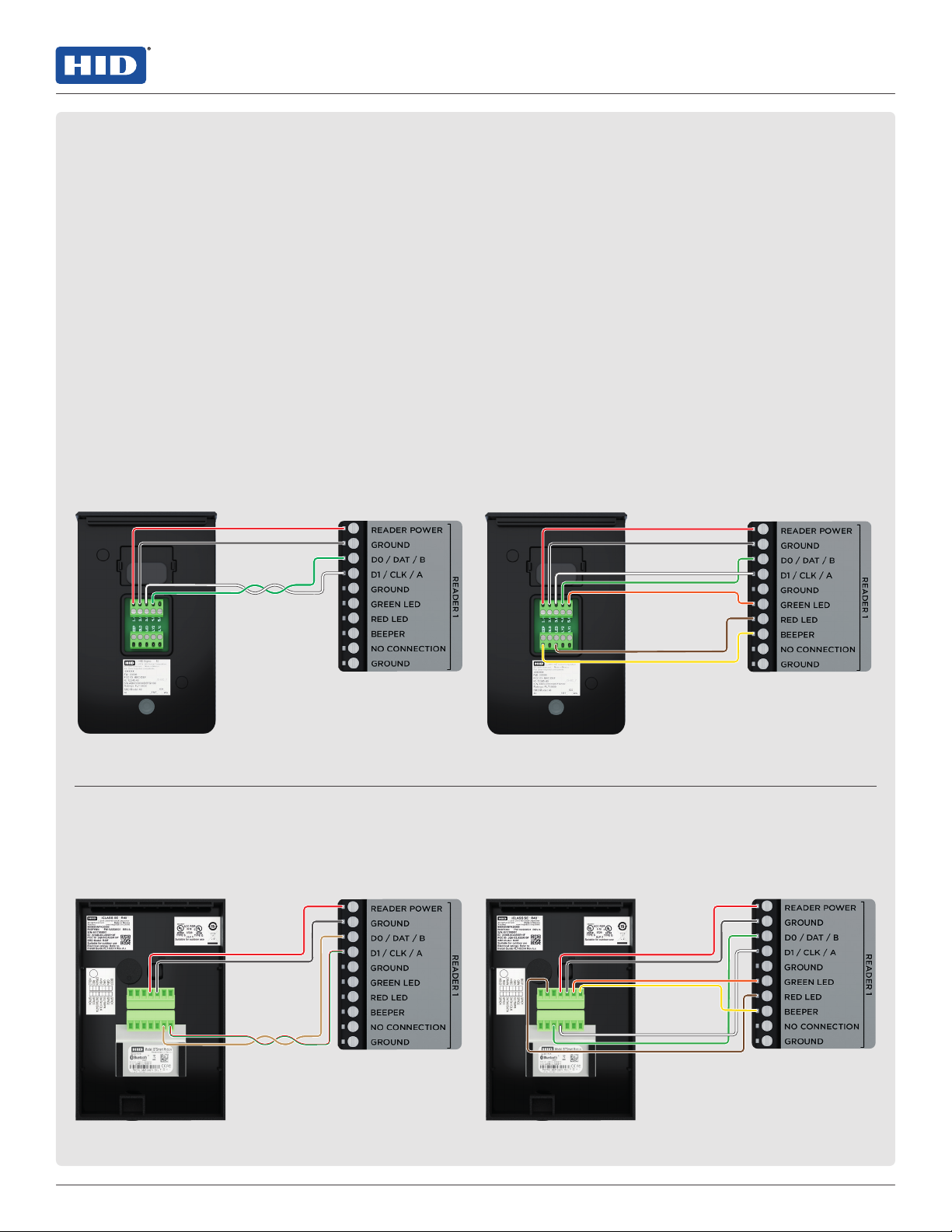
2. Communication wiring
Connect the X100 to the Aero X1100 intelligent
controller using IO Module ports (2-wire RS-485).
Use 1-twisted pair, shielded cable, 120Ωimpedance,
24 AWG, 4,000 ft. (1,219 m) maximum.
Note: Both IN and OUT terminals on the IO MODULE
are the same port and are internally connected.
Setting the termination jumpers
Install RS-485 termination jumpers on the interface
boards at each end of the communication bus only.
Failure to do so will compromise the proper operation
of the communication channel.
JUMPER DESCRIPTION
IN Install only on the first and last unit on the
communication bus.
OUT Install only if not the first or last unit on the
communication bus.
IO MODULE IN or IO MODULE OUT
3PLT-04234, Rev. A.3
HID Aero™ X100 Installation Guide
Powering
Trusted Identities
3. Connecting readers
OSDP (RS-485) signaling requires two 2-conductor
cables. One cable for power (18 AWG) and one
cable for communication (24 AWG, shielded,
twisted pair).
Wiegand or Clock/Data (TTL) signaling requires a
4-conductor cable (18 AWG, shielded) with additional
optional conductors for LED and beeper control.
CAUTION
Readers that require dierent voltage or have high
current requirements should be powered separately.
Refer to the reader manufacture specifications for
cabling requirements.
Note: For OSDP cable lengths greater than 200 ft
(61 m) or EMF interference, install 120Ω+/- 2Ωresistor
across RS-485 termination ends.
Note: Data 0 and Data 1 wires for Wiegand may be
reused for OSDP. However, standard Wiegand cable
may not meet RS-485 twisted pair recommendations.
The reuse of cable works best on shorter cable lengths
at lower data rates.
HID Signo reader
(Wiegand or Clock/Data installation)
Typical reader
(Wiegand or Clock/Data installation)
HID Signo™ reader
(OSDP installation)
Typical reader
(OSDP installation)
READER 1 or
READER 2
READER 1 or
READER 2
READER 1 or
READER 2
READER 1 or
READER 2
HID Aero™ X100 Installation Guide
PLT-04234, Rev. A.34
Powering
Trusted Identities
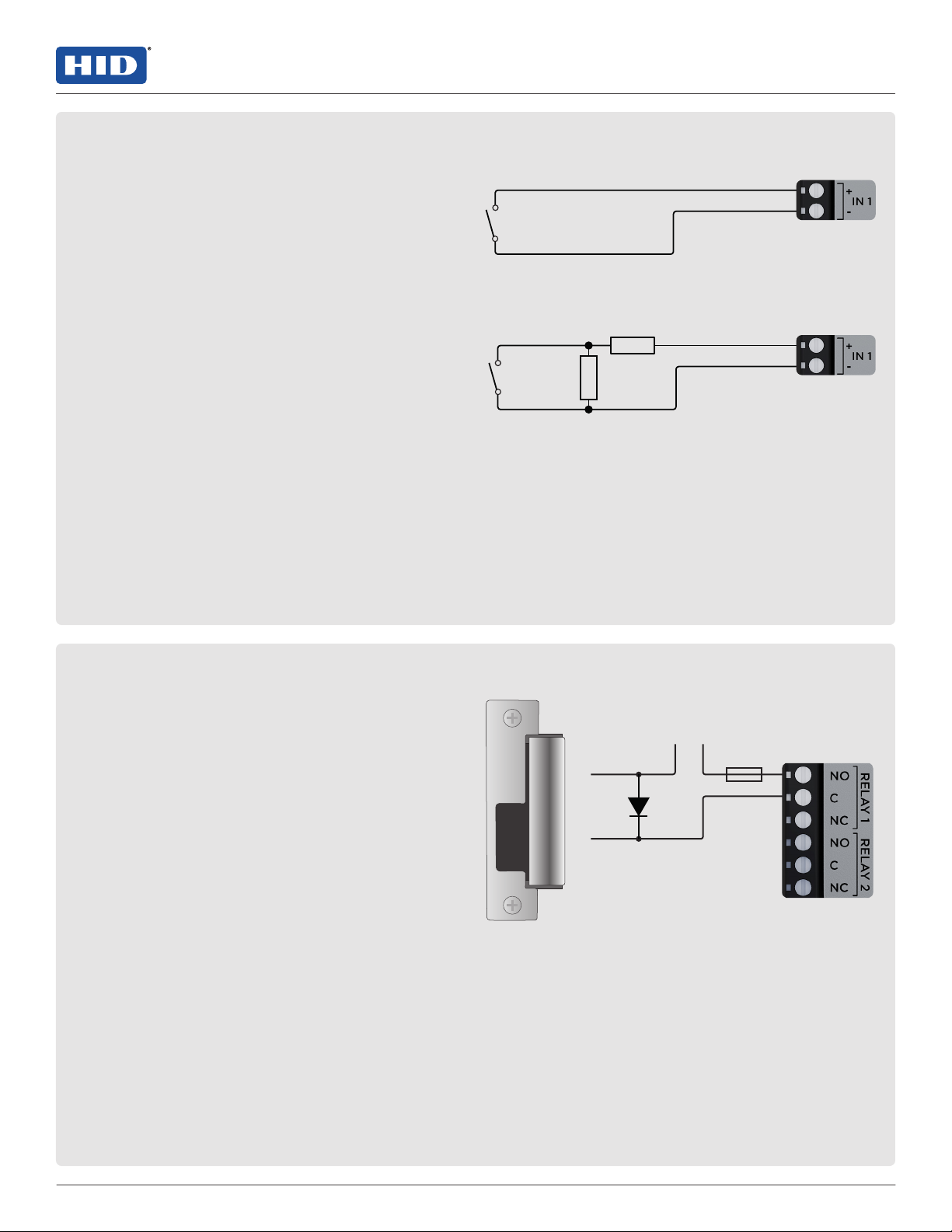
4. Input circuit wiring
Inputs are typically used for the following:
To monitor door position.
Request to exit.
Alarm contacts.
Input IN 1 to IN 4 circuits can be configured as
unsupervised or supervised and can use normally open
or normally closed contacts.
For a supervised circuit, add two 1KΩ, 1% resistors as
close to the sensor as possible.
Custom end of line (EOL) resistances may be configured
via the host software.
Note: The input circuit wiring configurations shown are
supported but may not be typical.
5. Relay circuit wiring
Four relays are provided for controlling door lock
mechanisms or alarm signaling.
When controlling the delivery of power to the door
strike, the NO (Normally Open) and C(Common) poles
are typically used.
When momentarily removing power to unlock the door,
as with a mag lock, the NC (Normally Closed) and C
(Common) poles are typically used.
Check with local building codes for proper egress door
installation.
CAUTION
Door lock mechanisms can generate feedback to the
relay circuit. This can cause damage and premature
failure of the relay, eecting the operation of the X100.
Use a diode to protect the relay. Use a wire of sucient
gauge to avoid voltage loss.
Diode selection:
Diode current rating: 1x strike current.
Diode breakdown voltage: 4x strike voltage.
For 12 V DC or 24 V DC strike, diode 1N4002
(100V/1A) typical.
- +
To DC power source
Diode
+
-Fuse
DC Strike
RELAY 1 to
RELAY 4
Unsupervised circuit IN 1 to IN 4
Supervised circuit IN 1 to IN 4
1K,1%
1K,1%

5PLT-04234, Rev. A.3
HID Aero™ X100 Installation Guide
Powering
Trusted Identities
6. DIP switch configuration
Switches 1 through 5 select the device address. Switches 6 and 7 select the communication baud rate.
Switch 8 is not in use.
1 2 3 4 5 6 7 8 SELECTION
OFF OFF OFF OFF OFF Address 0
ON OFF OFF OFF OFF Address 1
OFF ON OFF OFF OFF Address 2
ON ON OFF OFF OFF Address 3
OFF OFF ON OFF OFF Address 4
ON OFF ON OFF OFF Address 5
OFF ON ON OFF OFF Address 6
ON ON ON OFF OFF Address 7
OFF OFF OFF ON OFF Address 8
ON OFF OFF ON OFF Address 9
OFF ON OFF ON OFF Address 10
ON ON OFF ON OFF Address 11
OFF OFF ON ON OFF Address 12
ON OFF ON ON OFF Address 13
OFF ON ON ON OFF Address 14
ON ON ON ON OFF Address 15
OFF OFF OFF OFF ON Address 16
ON OFF OFF OFF ON Address 17
OFF ON OFF OFF ON Address 18
ON ON OFF OFF ON Address 19
OFF OFF ON OFF ON Address 20
ON OFF ON OFF ON Address 21
OFF ON ON OFF ON Address 22
ON ON ON OFF ON Address 23
OFF OFF OFF ON ON Address 24
ON OFF OFF ON ON Address 25
OFF ON OFF ON ON Address 26
ON ON OFF ON ON Address 27
OFF OFF ON ON ON Address 28
ON OFF ON ON ON Address 29
OFF ON ON ON ON Address 30
ON ON ON ON ON Address 31
OFF OFF 115,200 BPS
ON ON 38,400 BPS
OFF ON 19,200 BPS
ON OFF 9,600 BPS
Table of contents
Other HID Recording Equipment manuals


