HID Mercury MR52-S3 User manual

HIDMercury™
MR52-S3 Reader Interface
Installation and Specifications
PLT-05248, A.2
June 2021
HIDMercury™ MR52-S3 Reader Interface Installation and Specifications
Powering
Trusted Identities

Copyright
© 2020 - 2021 HID Global Corporation/ASSA ABLOY AB. All rights reserved.
This document may not be reproduced, disseminated or republished in any form without the prior written
permission of HID Global Corporation.
Trademarks
HID GLOBAL, HID, the HID Brick logo, the Chain Design, and HIDMercury are trademarks or registered
trademarks of HID Global, ASSA ABLOY AB, or its affiliate(s) in the US and other countries and may not be
used without permission. All other trademarks, service marks, and product or service names are trademarks
or registered trademarks of their respective owners.
Contacts
HID Global Technical Support: www.hidglobal.com/support.
Americas and Corporate Asia Pacific
611 Center Ridge Drive
Austin, TX 78753
USA
Phone: +1866 607 7339
19/F 625 King’s Road
North Point, Island East
Hong Kong
Phone: +852 3160 9833
Europe, Middle East, and Africa (EMEA) Brazil
3 Cae Gwyrdd
Green Meadow Springs
Cardiff CF15 7AB
United Kingdom
Phone: +44 (0) 1440 711 822
Condomínio Business Center
Av. Ermano Marchetti, 1435
Galpão A2 - CEP 05038-001
Lapa - São Paulo / SP Brazil
Phone: +55 11 5514-7100
For additional offices around the world, see www.hidglobal.com/contact/corporate-offices.
What's new
Date Description Revision
June 2021 Minor updates. A.2
A complete list of revisions is available in Revision history.
PLT-05248, A.2 2 June 2021
Powering
Trusted Identities HIDMercury™ MR52-S3 Reader Interface
Installation and Specifications

Section 01
Powering
Trusted Identities
Overview
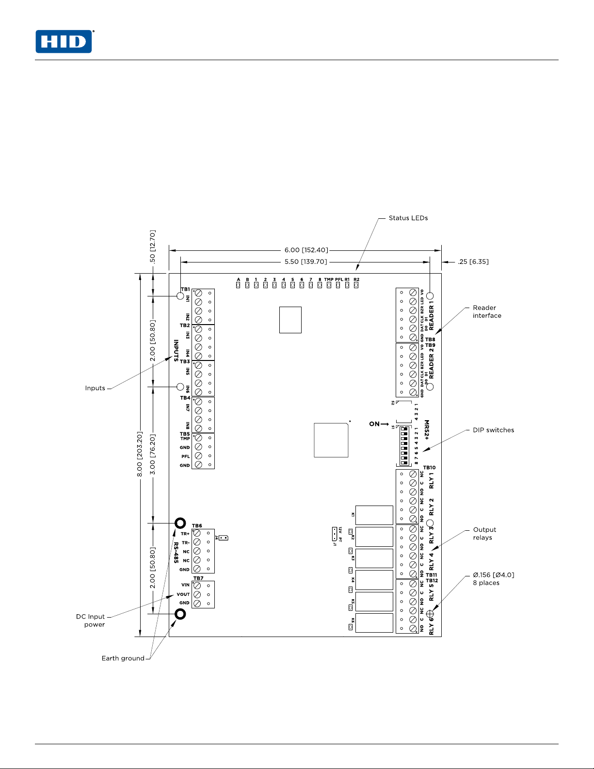
1.1 MR52 reader interface
The MR52 reader interface boards provide a solution to the OEM system integrator for interfacing to TTL
(D1/D0, Clock/Data), F/2F, 2-wire RS-485 device and door hardware. The MR52 provides a tristate LED
control, and buzzer control.
Six Form-C relay outputs are provided that can be used for strike control or alarm signaling.
Eight inputs are provided that can be used for monitoring the door contact, request to exit push button, and
alarm contacts. Input circuits can be configured as unsupervised or supervised.
The MR52 communicates to the controller via a 2-wire RS-485.
For component location see below (some components shown are not present on the MR52).
PLT-05248, A.2 4 June 2021
Powering
Trusted Identities HIDMercury™ MR52-S3 Reader Interface
Installation and Specifications

Section 02
Powering
Trusted Identities
MR52 wiring and setup

2.1 Supplying power to the MR52
The MR52 accepts 12 to 24 V DC for power on TB7 (VIN and GND). Locate the power source as close to the
MR52 as possible.
Make power connection with minimum of 18 AWG wires.
Observe POLARITY on VIN!
The VOUT terminal on TB7 is the same as VIN.
2.2 Communication wiring (SIO communication port)
The MR52 communicates with a HID Mercury Security intelligent controller (EP2500 for example) via a
2-wire RS-485 interface. The MR52 allows for multi-drop communication on a bus of up to 4,000 feet
(1,200 m). Use twisted pair (minimum 24 AWG) with drain wire and shield for communication.
See Specifications.
Install RS-485 termination jumper, J4, on the interface boards at each end of the communication line only.
2-wire RS-485 TB10
(only 2-wire RS-485 is supported)
PLT-05248, A.2 6 June 2021
Powering
Trusted Identities HIDMercury™ MR52-S3 Reader Interface
Installation and Specifications

2.3 Reader wiring
Each reader port supports a reader with TTL (D1/D0, Clock/Data), F/2F, or 2-wire RS-485 signaling. Power to
the reader is selectable: 12 V DC (VIN must be greater than 20 V DC), or power is passed-through (PT) from
the input voltage of the MR52 (TB7-VIN), 300 mA maximum per reader port. Readers that require different
voltage or have high current requirements must be powered separately. Refer to the reader manufacture
specifications for cabling requirements. In the 2-wire LED mode the buzzer output is used to drive the second
LED. Reader port configuration is set via the host software.
To fully utilize each reader port:
nTTL signaling requires a 6-conductor cable (18 AWG).
nF/2F signaling requires a 4-conductor cable.
nRS-485 signaling requires two 2-conductor cables. Use one cable for power (18 AWG) and one cable for
communication (24 AWG, with drain wire and shield).
Note: For OSDP cable lengths greater than 200 ft (61 m) or EMF interference, install 120Ω +/- 2Ω resistor
across RS-485 termination ends.
Note: Data 0 and Data 1 wires for Wiegand may be reused for OSDP. However, standard Wiegand cable may
not meet RS-485 twisted pair recommendations. The reuse of cable works best on shorter cable
lengths at lower data rates.
J1 – Reader port power select
12V PT Reader power
12 V DC is available on reader ports (VIN > 20 V DC)
VINpower is "Passed Through" to reader ports
Caution: If the input voltage to the MR52 is 12 V DC, jumper J1 MUST be in the PT position.
Input power Reader power select Reader output Notes
24 V DC Pass-through 24 V DC
24 V DC 12 V DC 12 V DC
12 V DC Pass-through 12 V DC
12 V DC 12 V DC 0 V DC Caution: Do not use
PLT-05248, A.2 7 June 2021
Powering
Trusted Identities HIDMercury™ MR52-S3 Reader Interface
Installation and Specifications
2.3.1 Reader wiring diagrams
Typical reader 1
(OSDP installation)
Typical reader 1
(Wiegand or Clock/Data installation)
Typical reader 2
(OSDP installation)
Typical reader 2
(Wiegand or Clock/Data installation)
Typical Unsupervised F/2F Reader Typical Supervised F/2F Reader
Jumper D1 to LED on supervised F/2F readers
*Inputs on supervised F/2F readers may be unsupervised or supervised (supervised shown).
PLT-05248, A.2 8 June 2021
Powering
Trusted Identities HIDMercury™ MR52-S3 Reader Interface
Installation and Specifications

2.4 Alarm contract wiring
There are eight inputs that are typically used to monitor door position, request to exit or alarm contacts.
Input circuits can be configured as:
nUnsupervised alarm (2 states); reporting as open or closed contact.
nSupervised alarm (6 states); reporting as open or closed contact, open circuit, shorted circuit, grounded
circuit*, or foreign voltage*.
A supervised input circuit requires adding two resistors with value of 1kΩ, 1% to the circuit to facilitate proper
reporting and should be located as close to the sensor as possible. Custom end of line (EOL) resistances can
be configured via the host software.
*Grounded and foreign voltage states are not a requirement of UL 294 and therefore not verified by UL.
The input circuit wiring configurations shown are supported but may not be typical:
2.5 Inputs for cabinet tamper/power fault
Input CT and input BA are used for monitoring cabinet tamper and power failure with normally closed
contacts. These two inputs are for contact closure monitoring only, and do not use EOL resistor(s). If these
inputs are not used, install a short piece of wire at the input to indicate a safe condition.
PLT-05248, A.2 9 June 2021
Powering
Trusted Identities HIDMercury™ MR52-S3 Reader Interface
Installation and Specifications
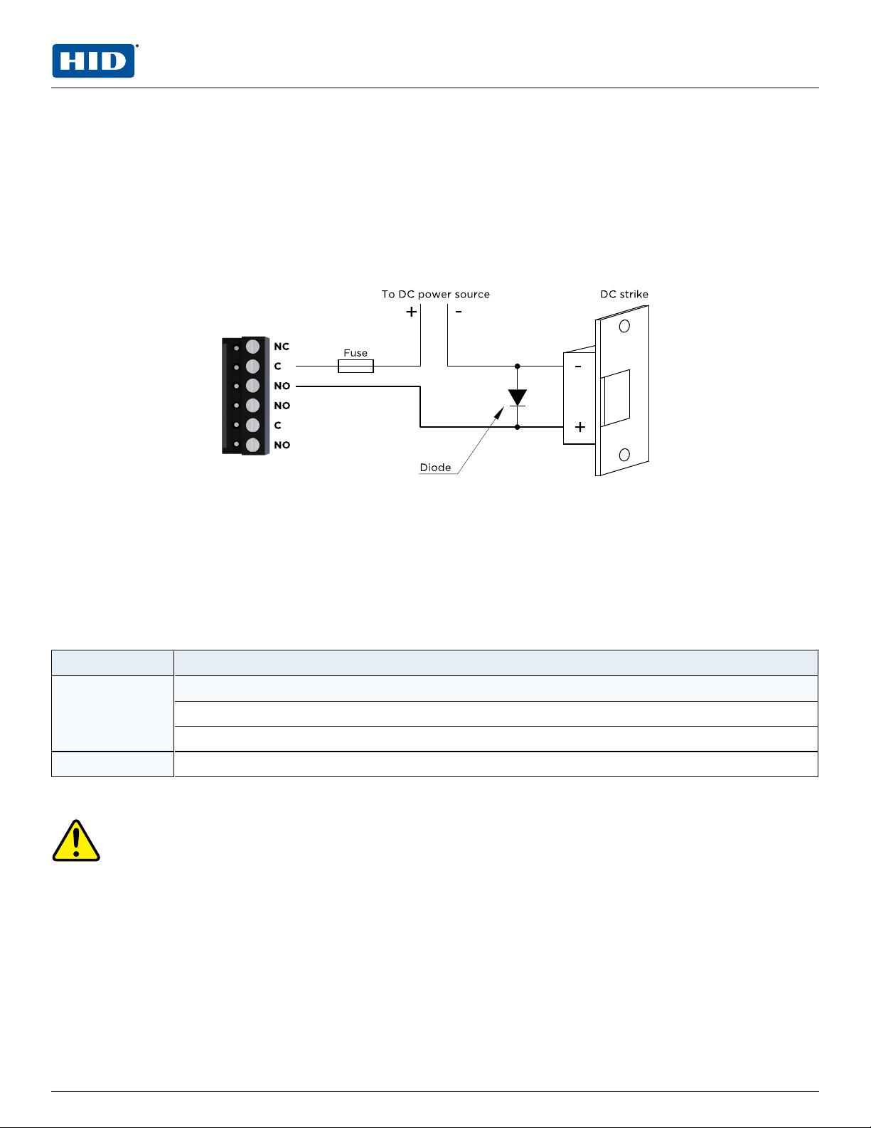
2.6 Control output wiring
Six Form-C contact relays are provided for controlling door strikes or other devices. Load switching can
cause abnormal contact wear and premature contact failure. Switching of inductive loads (strike) also causes
EMI (electromagnetic interference) which may interfere with normal operation of other equipment. To
minimize premature contact failure and to increase system reliability a contact protection circuit must be
used. The following two circuits are recommended. Locate the protection circuit as close to the load as
possible (within 12 inches [30 cm]), as the effectiveness of the circuit will decrease if it is located further
away.
Use sufficiently large gauge of wires for the load current to avoid voltage loss.
Diode selection
nDiode current rating > 1x strike current.
nDiode break down voltage: 4x strike voltage.
nFor 12 V DC or 24 V DC strike, diode 1N4002 (100V /1A) typical.
2.7 Jumpers
Jumper Description
J1 Reader power select
12V = 12 V DC at reader ports. See caution below.
PT = VIN “Passed Through" to reader ports
J4 RS-485 termination, install in first and last units only
Note: All other jumpers are for factory use only.
Caution: The input power (VIN) must be 20 V DC minimum if the 12 V DC selection is to be used.
PLT-05248, A.2 10 June 2021
Powering
Trusted Identities HIDMercury™ MR52-S3 Reader Interface
Installation and Specifications

2.8 Address, baud rate and encryption configuration switch
Switches 1 to 5 select the device address. Switch 6 and 7 select the communication baud rate. Switch 8
enables encrypted communication. All other configuration settings are set via host software.
S8 S7 S6 S5 S4 S3 S2 S1 Selection
OFF OFF OFF OFF OFF Address 0
OFF OFF OFF OFF ON Address 1
OFF OFF OFF ON OFF Address 2
OFF OFF OFF ON ON Address 3
OFF OFF ON OFF OFF Address 4
OFF OFF ON OFF ON Address 5
OFF OFF ON ON OFF Address 6
OFF OFF ON ON ON Address 7
OFF ON OFF OFF OFF Address 8
OFF ON OFF OFF ON Address 9
OFF ON OFF ON OFF Address 10
OFF ON OFF ON ON Address 11
OFF ON ON OFF OFF Address 12
OFF ON ON OFF ON Address 13
OFF ON ON ON OFF Address 14
OFF ON ON ON ON Address 15
ON OFF OFF OFF OFF Address 16
ON OFF OFF OFF ON Address 17
ON OFF OFF ON OFF Address 18
ON OFF OFF ON ON Address 19
ON OFF ON OFF OFF Address 20
ON OFF ON OFF ON Address 21
ON OFF ON ON OFF Address 22
ON OFF ON ON ON Address 23
ON ON OFF OFF OFF Address 24
ON ON OFF OFF ON Address 25
ON ON OFF ON OFF Address 26
ON ON OFF ON ON Address 27
ON ON ON OFF OFF Address 28
ON ON ON OFF ON Address 29
ON ON ON ON OFF Address 30
ON ON ON ON ON Address 31
PLT-05248, A.2 11 June 2021
Powering
Trusted Identities HIDMercury™ MR52-S3 Reader Interface
Installation and Specifications

S8 S7 S6 S5 S4 S3 S2 S1 Selection
OFF OFF 115,200 BPS1
OFF ON 9,600 BPS
ON OFF 19,200 BPS
ON ON 38,400 BPS
OFF Encrypted communication not required2
ON Encrypted communication required2
1. Firmware revisions prior to 1.38.1, this setting is 2,400 BPS.
2. Firmware revisions prior to 1.38.1, SW8 is not defined. Set to the OFF position.
PLT-05248, A.2 12 June 2021
Powering
Trusted Identities HIDMercury™ MR52-S3 Reader Interface
Installation and Specifications

2.9 Status LEDs
2.9.1 Power-up
All LEDs are OFF.
2.9.2 Initialization
Once power is applied, initialization of the module begins.
When initialization is completed, LEDs A through R2 are briefly sequenced ON then OFF.
2.9.3 Run time
After the above sequence, the LEDs have the following meanings:
LED Description
A LED
heartbeat and
on-line status
Off-line: 1 sec rate, 20% ON
On-line: Non-encrypted communication: 1 sec rate, 80% ON Encrypted communication: .1 sec ON, .1
sec OFF, .1 sec ON, .1 sec OFF, .1 sec ON, .1 sec OFF, .1 sec ON, .3 sec OFF
A LED Error Indication: Waiting for application firmware to be downloaded: .1 sec ON, .1 sec OFF.
B LED SIO Communication Port Status: Indicates communication activity on the SIO communication port
1 LED Input Status: IN1
2 LED Input Status: IN2
3 LED Input Status: IN3
4 LED Input Status: IN4
5 LED Input Status: IN5
6 LED Input Status: IN6
7 LED Input Status: IN7
8 LED Input Status: IN8
TMP Cabinet tamper
PFL Power fault
Input in the inactive state: OFF (briefly flashes ON every 3 seconds), Input in the active state: ON
(briefly flashes OFF every 3 seconds), Input in a trouble state: Rapid Flash.
R1 LED Reader port 1:
Clock/Data Mode: Flashes when data is received, either input
D1/D0 Mode: Flashes when data is received, either input
RS-485 Mode: Flashes when transmitting dataF/2F Mode: Flashes when data/acknowledgment is
received
R2 LED Reader port 2:
Clock/Data Mode: Flashes when data is received, either input
D1/D0 Mode: Flashes when data is received, either input
RS-485 Mode: Flashes when transmitting dataF/2F Mode: Flashes when data/acknowledgment is
received
K1 through
K6 LEDs
Illuminates when output relay RLY 1 (K1) through RLY 6 (K6) is energized.
Every three seconds, LEDs A through R2 are pulsed to their opposite state for 0.1 sec.
PLT-05248, A.2 13 June 2021
Powering
Trusted Identities HIDMercury™ MR52-S3 Reader Interface
Installation and Specifications

Section 03
Powering
Trusted Identities
Specifications

Revision D assembly:
The Interface is for use in low voltage, class 2 circuits only.
The installation of this device must comply with all local fire and electrical codes.
Primary power 12 to 24 V DC ± 10%, 550 mA maximum (reader current not included)
Outputs Six Form-C relays
Normally open contact (NO) contact: 5 A @ 30 V DC resistive
Normally closed contact (NC) contact: 3 A @ 30 V DC resistive
Inputs Eight unsupervised/supervised, standard EOL: 1k/1kΩ, 1%, ¼ watt
Two unsupervised, dedicated for cabinet tamper and UPS fault monitoring
Reader interface
Power
(jumper selectable)
12 V DC ± 10% regulated, 300 mA maximum each reader
(input voltage (VIN) must be greater than 20 V DC)
or
12 to 24 V DC ± 10% (input voltage passed through), 300 mA maximum each reader
Data inputs TTL compatible, F/2F or 2-wire RS-485
LED output TTL compatible, high > 3 V, low < 0.5 V, 5 mA source/sink maximum
Buzzer output Open collector, 12 V DC open circuit maximum, 40 mA sink maximum
Communication 2-wire RS-485: 9600, 19200, 38400 or 115200 bps
Cable requirements
Power 1 twisted pair, 18 AWG
RS-485 I/O devices 1 twisted pair with drain wire and shield, 24 AWG, 120Ω impedance, 4,000 feet
(1,200 m) maximum
Alarm inputs One twisted pair per input, 30Ω maximum
Outputs As required for the load
Reader data (TTL) 6-conductor, 18 AWG, 500 feet (150 m) maximum
Reader data (F/2F) 4-conductor, 18 AWG, 500 feet (150 m) maximum
Reader data (RS-485) 1 twisted pair with drain wire and shield, 24 AWG, 120Ω impedance, 2,000 feet
(610 m) maximum
Mechanical
Dimension 6 inches (15 2 mm) W x 8 inches (203 mm) L x 1 inches (25 mm) H
Weight 11 oz. (312 g) nominal
Environment
Storage temperature -55 to +85°C
Operating temperature 0 to +70°C
Humidity 5 to 95% RHNC
PLT-05248, A.2 15 June 2021
Powering
Trusted Identities HIDMercury™ MR52-S3 Reader Interface
Installation and Specifications

UL294, 6th edition Performance Levels
Feature Level
Standby Power I
Endurance IV
Line Security I
Destructive Attack I
These specifications are subject to change without notice.
3.1 Warranty
Mercury Security warrants the product is free from defects in material and workmanship under normal use
and service with proper maintenance for one year from the date of factory shipment. Mercury Security
assumes no responsibility for products damaged by improper handling or installation. This warranty is limited
to the repair or replacement of the defective unit.
There are no expressed warranties other than set forth herein. Mercury Security does not make, nor intends,
nor does it authorize any agent or representative to make any other warranties, or implied warranties, and
expressly excludes and disclaims all implied warranties of merchantability or fitness for a particular purpose.
Returns must be accompanied by a Return Material Authorization (RMA) number obtained from customer
service, and prepaid postage and insurance.
3.2 Liability
The Interface should only be used to control exits from areas where an alternative method for exit is
available. This product is not intended for, nor is rated for operation in life-critical control applications.
Mercury Security is not liable under any circumstances for loss or damage caused by or partially caused by
the misapplication or malfunction of the product. Mercury Security’s liability does not extend beyond the
purchase price of the product.
3.3 Regulatory
This device complies with part 15 of the FCC Rules. Operation is subject to the following two conditions: (1)
This device may not cause harmful interference, and (2) this device must accept any interference received,
including interference that may cause undesired operation.
PLT-05248, A.2 16 June 2021
Powering
Trusted Identities HIDMercury™ MR52-S3 Reader Interface
Installation and Specifications


hidglobal.com An ASSAABLOY Group brand
Dummy text.
Powering
Trusted Identities PLT-05248, A.2
Americas & Corporate
611 Center Ridge Drive
Austin, TX 78758
USA
Asia Pacific
19/F 625 King's Road
North Point
Island East
Hong Kong
Europe, Middle East & Africa
3 Cae Gwyrdd
Green Meadow Springs
Cardiff, CF15 7AB
United Kingdom
Brazil
Condomínio Business Center
Av. Ermano Marchetti, 1435
Galpão A2 - CEP 05038-001
Lapa - São Paulo / SP, Brazil
Support: +1 866-607-7339 Support: +852-3160-9833 Support: +44 (0) 1440 711 822 Phone: +55 11 5514-7100
Table of contents
Other HID Recording Equipment manuals


