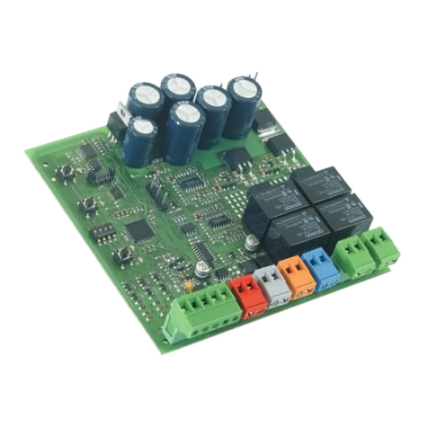
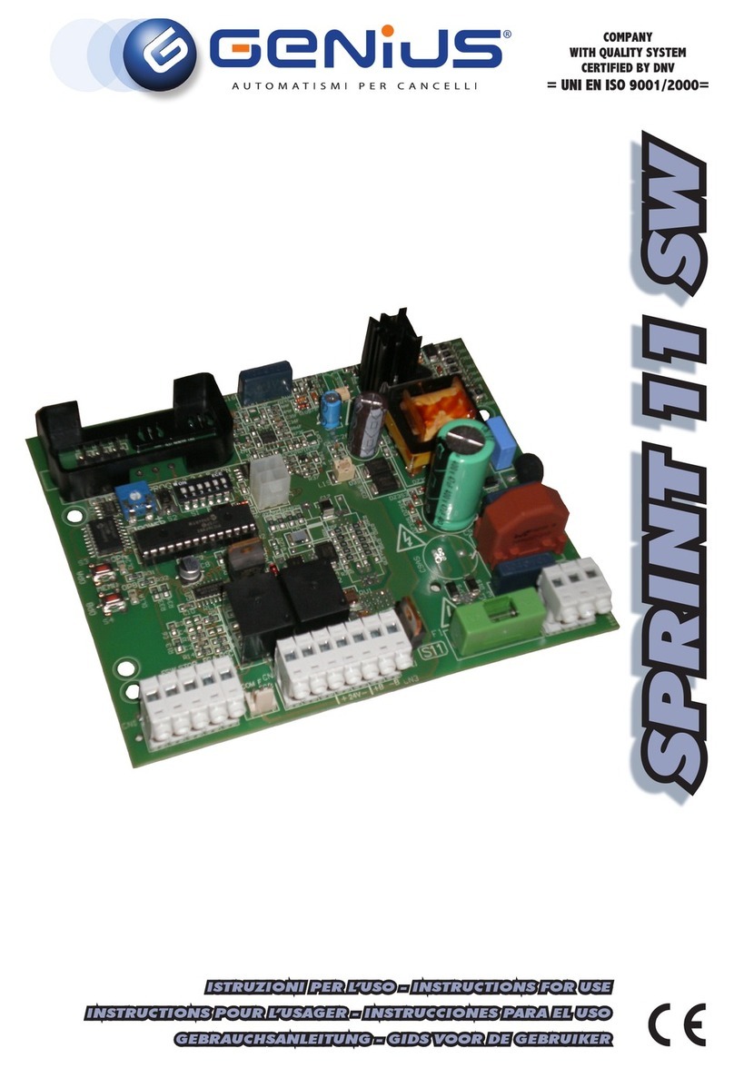
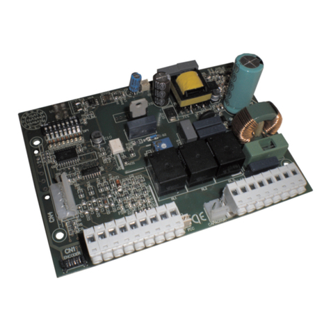
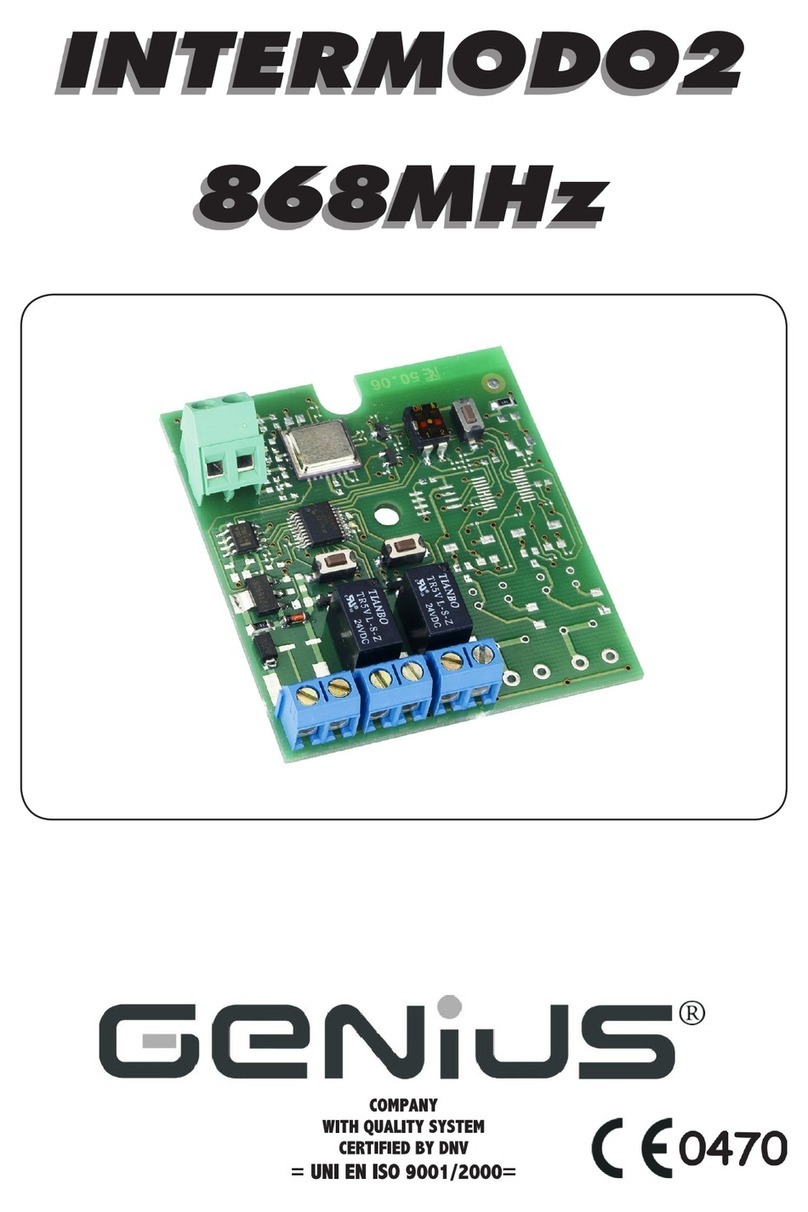
Genius JA592 Technical manual

JA592
APPARECCHIATURA ELETTRONICA PER CANCELLI A BATTENTE 230V
CONTROL BOARD FOR 230V HINGED GATES
PLATINE ELECTRONIQUE POUR PORTAILS BATTANTS 230V
EQUIPO ELECTRÓNICO PARA PORTONES DE TIPO BATIENTE 230V
ELEKTRONISCHES GERÄT FÜR FLÜGELTORE 230V
ISTRUZIONI PER L’USO – NORME DI INSTALLAZIONE
USE AND INSTALLATION INSTRUCTIONS
INSTRUCTIONS POUR L’EMPLOI – NORMES D’INSTALLATION
INSTRUCCIONES PARA EL USO – NORMAS DE INSTALACIÓN
BETRIEBSANLEITUNG - INSTALLATIONSVORSCHRIFTEN

AVVERTENZEPERL’INSTALLATORE
OBBLIGHI GENERALI PER LA SICUREZZA
1) ATTENZIONE! È importante per la sicurezza delle persone seguire attenta-
mentetuttal’istruzione.Unaerratainstallazioneounerratousodelprodotto
può portare a gravi danni alle persone.
2) Leggere attentamenteleistruzioniprimadi iniziare l’installazione delprodot-
to.
3) I materiali dell’imballaggio (plastica, polistirolo, ecc.) non devono essere
lasciatiallaportatadeibambiniin quanto potenziali fonti di pericolo.
4) Conservare le istruzioni per riferimenti futuri.
5) Questo prodottoèstatoprogettatoecostruitoesclusivamenteperl’utilizzo
indicatoinquesta documentazione.Qualsiasialtroutilizzo nonespressamen-
teindicato potrebbe pregiudicare l’integrità del prodotto e/o rappresen-
tare fonte di pericolo.
6) GENIUS declinaqualsiasiresponsabilitàderivata dall’uso improprioodiverso
daquellopercuil’automatismoè destinato.
7) Non installarel’apparecchioinatmosfera esplosiva:lapresenzadi gas ofumi
infiammabilicostituisceungravepericoloper la sicurezza.
8) Gli elementi costruttivi meccanici devono essere in accordo con quanto
stabilito dalle Norme EN 12604 e EN 12605.
Peri Paesi extra-CEE, oltre ai riferimenti normativi nazionali, per ottenere un
livellodisicurezzaadeguato,devonoessere seguite le Norme soprariporta-
te.
9) GENIUS nonèresponsabiledell’inosservanzadellaBuonaTecnicanellaco-
struzione delle chiusure da motorizzare, nonché delle deformazioni che
dovesserointervenirenell’utilizzo.
10) L’installazionedeveessereeffettuata nell’osservanza delle Norme EN12453
eEN 12445. Il livello di sicurezza dell’automazione deve essere C+E.
11) Primadieffettuarequalsiasi intervento sull’impianto,toglierel’alimentazione
elettrica.
12) Prevedere sulla rete di alimentazione dell’automazione un interruttore
onnipolarecondistanzad’aperturadeicontatti uguale o superiore a3mm.
Èconsigliabilel’uso diunmagnetotermico da6Aconinterruzione onnipolare.
13) Verificarecheamontedell’impiantovisiauninterruttoredifferenzialecon
sogliada0,03 A.
14) Verificare che l’impianto di terra sia realizzato a regola d’arte e collegarvi
lepartimetallichedellachiusura.
15) L’automazionedisponediunasicurezza intrinseca antischiacciamento co-
stituitadauncontrollo di coppia.E'comunquenecessarioverificarne la sogli
diinterventosecondoquantoprevistodalleNormeindicatealpunto10.
16) I dispositivi di sicurezza (norma EN 12978) permettono di proteggere even-
tuali aree di pericolo da Rischi meccanici di movimento, come ad Es.
schiacciamento,convogliamento,cesoiamento.
17) Perogniimpiantoè consigliato l’utilizzo dialmenounasegnalazionelumino-
sanonchédi un cartellodisegnalazionefissato adeguatamentesullastruttu-
radell’infisso, oltre ai dispositivi citati al punto “16”.
18) GENIUSdeclinaogniresponsabilità ai finidellasicurezzaedel buonfunziona-
mentodell’automazione,in casovenganoutilizzaticomponenti dell’impian-
tonondiproduzioneGENIUS.
19) Perlamanutenzioneutilizzareesclusivamenteparti originali GENIUS.
20) Non eseguire alcuna modifica sui componenti facenti parte del sistema
d’automazione.
21) L’installatore deve fornire tutte le informazioni relative al funzionamento
manuale del sistema in caso di emergenza e consegnare all’Utente
utilizzatoredell’impiantoil libretto d’avvertenze allegato al prodotto.
22) Nonpermettereaibambini o personedisostarenellevicinanze del prodotto
duranteilfunzionamento.
23) Tenerefuoridallaportata dei bambiniradiocomandioqualsiasialtro datore
diimpulso,perevitarechel’automazionepossaessereazionatainvolonta-
riamente.
24) Iltransitotraleante deve avvenire solo a cancello completamenteaperto.
25) L’Utente utilizzatore deve astenersi da qualsiasi tentativo di riparazione o
d’interventodirettoe rivolgersi solo a personale qualificato.
26) Tutto quello che non è previsto espressamente in queste istruzioni non è
permesso
IMPORTANT NOTICE FOR THE INSTALLER
GENERAL SAFETY REGULATIONS
1) ATTENTION! To ensure the safety of people, it is important that you read
all the following instructions. Incorrect installation or incorrect use of the
product could cause serious harm to people.
2) Carefully readtheinstructionsbeforebeginningtoinstalltheproduct.
3) Do not leave packing materials (plastic,polystyrene,etc.) within reachof
childrenas such materials are potential sources of danger.
4) Storetheseinstructionsfor futurereference.
5) This product was designed and built strictly for the use indicated in this
documentation.Anyotheruse, not expresslyindicatedhere,could compro-
mise the good condition/operation of the product and/or be a source of
danger.
6) GENIUS declinesallliabilitycausedbyimproper use or use other thanthatfor
whichtheautomated systemwasintended.
7) Do not install the equipment in an explosive atmosphere: the presence of
inflammablegasorfumesisaseriousdangerto safety.
8) The mechanicalpartsmustconformtotheprovisionsofStandardsEN12604
andEN12605.
For non-EU countries, to obtain an adequate level of safety, the Standards
mentionedabovemustbeobserved,in additiontonational legalregulations.
9) GENIUS is not responsible for failure to observe Good Technique in the
constructionoftheclosingelements to bemotorised,orforanydeformation
thatmayoccurduringuse.
10) Theinstallationmustconform to StandardsEN12453and EN 12445.Thesafety
leveloftheautomatedsystemmust be C+E.
11) Beforeattemptinganyjobonthesystem,cutoutelectricalpower.
12) The mains power supply of the automatedsystemmustbefittedwithanall-
pole switch with contact opening distance of 3mm or greater. Use of a 6A
thermalbreakerwith all-pole circuit break is recommended.
13) Makesurethatadifferential switch with threshold of 0.03 Aisfittedupstream
ofthesystem.
14) Make sure that the earthing system is perfectly constructed, and connect
metal parts of the means of the closure to it.
15) Theautomatedsystemis suppliedwithanintrinsic anti-crushing safetydevice
consisting of a torque control. Nevertheless, its tripping threshold must be
checkedasspecifiedintheStandardsindicatedatpoint10.
16) The safety devices (EN 12978 standard) protect any danger areas against
mechanicalmovementRisks,such as crushing,dragging,andshearing.
17) Useofatleastoneindicator-lightisrecommendedforeverysystem,aswell
asawarningsign adequately secured to the frame structure, in addition to
thedevicesmentionedatpoint“16”.
18) GENIUSdeclinesallliabilityas concerns safety and efficient operationofthe
automatedsystem,if systemcomponentsnotproduced byGENIUSareused.
19) Formaintenance,strictlyuseoriginalparts by GENIUS.
20) Donotinanyway modify the components oftheautomatedsystem.
21) Theinstallershallsupplyall information concerning manual operation of the
systemincase of anemergency,andshall handovertothe user thewarnings
handbooksuppliedwiththe product.
22) Donotallowchildrenoradultstostayneartheproductwhileitisoperating.
23) Keep remote controls or other pulse generators away from children, to
preventtheautomatedsystemfrom being activated involuntarily.
24) Transitthroughtheleavesisallowed only when the gate is fully open.
25) The user must not attempt any kind of repair or direct action whatever and
contactqualifiedpersonnelonly.
26) Anything not expressly specified in these instructions is not permitted.
CONSIGNES POUR L'INSTALLATEUR
RÈGLES DE SÉCURITÉ
1) ATTENTION! Il est important, pour la sécurité des personnes, de suivre à la
lettre toutes les instructions. Une installation erronée ou un usage erroné
du produit peut entraîner de graves conséquences pour les personnes.
2) Lire attentivement les instructions avant d'installer le produit.
3) Les matériauxd'emballage(matièreplastique, polystyrène, etc.)nedoivent
pas être laissés à la portée des enfants car ils constituent des sources
potentiellesdedanger.
4) Conserver lesinstructionspourlesréférencesfutures.
5) Ce produitaétéconçu et construitexclusivementpourl'usageindiqué dans
cette documentation. Toute autre utilisation non expressément indiquée
pourraitcompromettre l'intégrité du produit et/ou représenter une source
dedanger.
6) GENIUS décline toute responsabilité qui dériverait d'usage impropre ou
différentdeceluiauquell'automatismeest destiné.
7) Ne pas installer l'appareil dans une atmosphère explosive: la présence de
gazoudefuméesinflammables constitue un grave dangerpourlasécurité.
8) Les composantsmécaniquesdoivent répondreauxprescriptionsdesNormes
EN 12604 et EN 12605.
PourlesPaysextra-CEE,l'obtentiond'unniveau de sécurité approprié exige
nonseulementlerespect des normesnationales,maiségalementle respect
desNormessusmentionnées.
9) GENIUS n'estpasresponsabledu non-respect delaBonneTechnique dans la
constructiondesfermeturesàmotoriser,nidesdéformationsquipourraient
intervenirlorsde l'utilisation.
10) L'installationdoitêtreeffectuéeconformémentauxNormes EN 12453 et EN
12445.Leniveaudesécuritédel'automatismedoitêtreC+E.
11) Couperl'alimentationélectriqueavanttoute intervention sur l'installation.
12) Prévoir, sur le secteur d'alimentation de l'automatisme, un interrupteur
omnipolaireavecunedistanced'ouverturedescontactségaleousupérieure
à 3 mm. On recommande d'utiliser un magnétothermique de 6A avec
interruptionomnipolaire.
13) Vérifierqu'ilyait,enamontdel'installation,un interrupteur différentiel avec
unseuilde0,03A.
14) Vérifierquelamiseàterreestréaliséeselonlesrèglesdel'artetyconnecter
lespiècesmétalliquesdelafermeture.
15) L'automatismedisposed'unesécuritéintrinsèque anti-écrasement, formée
d'un contrôle du couple. Il est toutefois nécessaire d'en vérifier le seuil
d'interventionsuivantlesprescriptionsdesNormesindiquées au point 10.
16) Les dispositifs de sécurité (norme EN 12978) permettent de protéger des
zones éventuellement dangereuses contre les Risques mécaniques du
mouvement,commel'écrasement, l'acheminement, lecisaillement.
9
ENGLISH
230 VAC
50 Hz
24 Vdc
3 W
J4 J1
J3
PE N L
MAIN
12 45678
COM OP
M1 COM OP
M2 CL
LA M P
9 10111213141516171819
OPEN
AB
STP
CL OP
FSW
---
+24V
++
-TX
FSW
20 21
W.L.
LO C K
J5
3
230 VAC
max.60W
12 V ac
J6
22
23
24 25
FC A 1
FC C 1
FC A 2
FC C 2
C1
M1
C2
M2
3. LAYOUT AND COMPONENTS
Fig. 1
NB.: Capacitors are supplied with the operators. Fig. 2
J4 J1
J3
F1
F2
1234
910111256781234
PEN L
MAIN
12 45678
COM OP
M1 COM OP
M2 CL
LA M P
9 10111213141516171819
OPEN
AB
STP
CL OP
FSW
---
+24V
++
-TX
FSW
J2
F
DL10
OP_A OP_B
STOP FSWOPFSWCL
20 21
W.L.
LO C K
J5
22
23
24 25
FCA1
FCC1
FCA2
FCC2
J6
FCA2FCA1
FCC2FCC1
TOTALLYOPEN
OPEN LEAF 1
STOP
1. WARNINGS
Important: Before attempting any work on the control board
(connections, maintenance), always turn off power.
- Install, upstream of the system, a differential thermal breaker
(Residual Current Device) withadequate tripping threshold.
- Connectthe earth cableto the appropriateterminalon theJ3
connector of the equipment (see fig.2).
- Alwaysseparate powercables fromcontrol andsafety cables
(push-button, receiver,photocells,etc.).Toavoidanyelectric
noise,use separate sheathsor a shieldedcable(with earthed
shield).
CONTROL BOARD JA592
4. ELECTRIC CONNECTIONS
F1
F2
J1
J3 J4 J5 J6
LIMIT-SWITCH
2. TECHNICAL SPECIFICATIONS
Powersupply 230 V~( +6% -10%) - 50Hz
Absorbedpower 10W
Motormax.load 800W
Accessoriesmax.load 0,5A
Electriclockmax.load 15VA
Operatingambienttemperature -20°C+55 °C
Protectionfuses 2 (see fig. 1)
Functionlogics Automatic/Semi-automatic/ "Stepped"safety devices/
Semi-automaticB/Dead-manC/"Stepped"semi-automatic
Opening/closingtime Programmable (from 0 to 120 s)
Pausetime 0, 10, 20, 30, 60, 120 s
Closingleafdelay
0, 5, 10, 20 s
Openingleafdelay 2 s (Canbedisabledwiththedip-switch)
Thrustforce Dip-switchadjustableon8levels for eachmotor
Terminalboardinputs Open/Openfreeleaf/ Stop/Limit-switch
Openingsafetydevices/Closingsafetydevices / Power supply +Earth
Terminalboardoutputs Flashinglamp-Motors-24Vdcaccessoriespowersupply
-24Vdcindicator-light-Failsafe-12Vacelectriclockpowersupply
Rapid connector Rapid connector 5 pins
Selectable functions Logics and pause times - Thrust force -
Opening and closing leaf delay - Reversing stroke -
Fail safe - Closing safety devices logic - Pre-flashing
Programming key
Simple
or
Advanced
work time learning,
with or without Limit-switch and/or encoder
For connection of
thephotocells
andsafety
devices,see
paragraph4.1.
BLUE
BLUE
F
J2
Led
DL10
DS1 DS2
LedOP_A TOTALLYOPENLED
Led OP_B LED: OPEN LEAF 1 / CLOSE
Led STOP LED STOP
Led FSWCL LED: CLOSING SAFETY DEVICES
Led FSWOP LED: OPENING SAFETY DEVICES
LedFCA1 LED:LEAF 1 OPENINGLIMIT-SWITCH
LedFCC1 LED:LEAF 1 CLOSINGLIMIT-SWITCH
LedFCA2 LED:LEAF 2 OPENINGLIMIT-SWITCH
LedFCC2 LED:LEAF 2 CLOSINGLIMIT-SWITCH
DL10 LED:TIMELEARNING SIGNALLING
J1 LOWVOLTAGETERMINAL BOARD
J2 RAPID CONNECTOR 5 PINS
J3 230 VAC POWER SUPPLY TERMINAL BOARD
J4 MOTORS AND FLASHING LAMP CONNECTION TERMINAL BOARD
J5 INDICATOR-LIGHT AND ELECTRIC LOCK TERMINAL BOARD
J6 LIMIT-SWITCH AND ENCODER TERMINAL BOARD
F1 MOTORS AND TRANSFORMER PRIMARY WINDING FUSE (F 5A)
F2 LOW VOLTAGE AND ACCESSORIES FUSE (T 800mA)
FTIME LEARNING SELECTION PUSH-BUTTON
DS1 1ST GROUP OF MICROSWITCH PROGRAMMING
DS2 2ND GROUP OF MICROSWITCH PROGRAMMING
ATTENTION:when
connecting,observe the
sequencephase/neutral.

10
ENGLISH
4.1. Connection of photocells and safety devices
Before connecting the photocells (or other devices) we advise
youto select thetype of operation according tothe movement
area they have to protect (see fig.3):
Opening safety devices:
they operate only during the gate
openingmovementand,therefore, theyaresuitablefor
protectingthe area between theopening leaves and
fixed obstacles (walls, etc) against the risk of impact
and crushing.
Closingsafetydevices:
theyoperate onlyduringthe gateclosing
movement and, therefore, they are suitable for
protecting the closing area against the risk of impact.
Opening/closingsafety devices
Closingsafety devices Opening
safetydevices
1
2
5
4
3
1
2
RX CL TX CL
1
2
5
4
3
1
2
RX OP/CL
TX OP/CL
-
+
-
+
1
2
5
4
3
1
2
RX OP TX OP
-
+
-
+
9 10111213141516171819
OPEN
AB
STP
CL OP
FSW
---
+24V
++
-TX
FSW
20 21
W.L.
LO C K
Connection of a pair of closing photocells and a pair of
opening/closing photocells (recommended lay-out)
9 10111213141516171819
OPEN
AB
STP
CL OP
FSW
---
+24V
++
-TX
FSW
20 21
W.L.
LO C K
1
2
5
4
3
1
2
RX CL TX CL
1
2
5
4
3
1
2
RX OP/CL
TX OP/CL
-
+
-
+
Fig. 3
Opening/closing safety devices:
they operate during the gate
opening and closing movements and, therefore, they
are suitable for the opening and closing areas against
the risk of impact.
It is recommends use of the lay-out in fig. 4 (in the event of fixed
obstacles at opening) or in fig. 5 (no fixed obstacles).
N.B. If two or more devices have the same function (opening or
closing), they should be connected to each other in series (see
fig. 12). N.C. contacts must be used.
Connection of a closing safety device and an opening
safety device
9 10111213141516171819
OPEN
AB
STP
CL OP
FSW
---
+24V
++
-TX
FSW
20 21
W.L.
LO C K
Fig. 6
Connection of a pair of closing photocells, a pair of
opening photocells and a pair of opening/closing
photocells (recommended lay-out)
Fig. 4
Connection of no safety device
9 10111213141516171819
OPEN
AB
STP
CL OP
FSW
---
+24V
++
-TX
FSW
20 21
W.L.
LO C K
Fig. 7
Fig. 5
Connection of 1 pair of opening photocells
1
2
5
4
3
1
2
RX TX
-
+
-
+
9 10111213141516171819
OPEN
AB
STP
CL OP
FSW
---
+24V
++
-TX
FSW
20 21
W.L.
LO C K
Fig. 8

11
ENGLISH
Connection of a pair of opening photocells and a pair of
closing photocells
1
2
5
4
3
1
2
RX CL
TX CL
1
2
5
4
3
1
2
RX OP TX OP
-
-
-
-
+
+
+
+
9 10111213141516171819
OPEN
AB
STP
CL OP
FSW
---
+24V
++
-TX
FSW
20 21
W.L.
LO C K
9 10111213141516171819
OPEN
AB
STP
CL OP
FSW
---
+24V
++
-TX
FSW
20 21
W.L.
LO C K
1
2
5
4
3
1
2
RX CL1 TX CL1
1
2
5
4
3
1
2
RX CL2
TX CL2
-
+
-
+
Fig. 11
Connection of two pairs of closing photocells
Fig. 10
1
2
5
4
3
1
2
RX TX
-
+
-
+
9 10111213141516171819
OPEN
AB
STP
CL OP
FSW
---
+24V
++
-TX
FSW
20 21
W.L.
LO C K
Fig. 9
Connection of 1 pair of closing photocells
Fig. 12
Fig. 13
Connection of 2 N.C. contacts in series
(e.g. Photocells, Stop)
Connection of 2 N.O. contacts in parallel
(e.g. Open A, Open B)
4.2. Terminal board J3 - Power supply (fig. 2)
PE: Earth connection
N:230 V~ power supply ( Neutral )
L:230 V~ power supply ( Line )
NB.:For correctoperation, theboardmust beconnected tothe
earthconductor in the system.Install an adequate differential
thermal breaker (RCD) upstream of the system.
4.3. Terminal board J4 - Motors and flashing lamp (fig. 2)
M1 : Terminals 1/2/3 = COM/OP/CL: Connection to Motor 1
Can be used in the single-leaf application
M2 : Terminals 4/5/6 = COM/OP/CL: Connection to Motor 2
Cannot be used in the single-leaf application
LAMP : Terminals 7/8 = Flashing lamp output ( 230 V ~)
4.4. Terminal board J1 - Accessories (fig. 2)
OPEN A - Terminal 9 plus a negative = "Total Opening"
command (N.O.): any pulse generator (push-button,
detector,etc.) which,by closinga contact,commands
opening and/or closing of both gate leaves.
Toinstall several fullopening pulsegenerators, connect
the N.O. contacts in parallel (see fig.13).
OPEN B - Terminal 10 plus a negative = "Partial Opening"
command(N.O.) / Closing: any pulse generator (push-
button, detector, etc.) which, by closing a contact,
commandsopening and/orclosingof theleaf drivenby
motor M1. In the Band Clogics, it always commands
closingof both leaves.
To install several partial opening pulse generators,
connect the N.O. contacts in parallel (see fig.13).
STP - Terminal 11plusa negative= STOPcontact (N.C.): any
device (e.g. a push-button) which, by opening a
contact, is able to stop gate movement.
ToinstallseveralSTOPdevices,connectthe N.C.contacts
inseries (see fig.12).
NB.:If STOPdevicesarenotconnected, jumperconnect
the STP terminals and - common.
CLFSW-Terminal12plus anegative = Closingsafetydevices
contact(N.C.): Thepurpose oftheclosing safetydevices
are to protect the leaf movement area during closing.
During closing, in the A-SP-E-EPlogics,thesafety devices
reverse the movement of the gate leaves, or stop and
reverse the movement when they are released (see
programmingofmicroswitchDS2-SW2).Duringtheclosing
cycle in logics Band C, they interrupt movement. They
never operate during the opening cycle. If the closing
safety devices operate when the gate is open, they
preventthe leafclosing movement.
NB.: If no closing safety devices are connected, jumper
connect terminals CL and -TX FSW (fig. 7).

12
ENGLISH
OPFSW-
Terminal13plusanegative=
Openingsafetydevices
contact (N.C.): Thepurposeof theopening safety devices
are to protect the leaf movement area during opening.
Duringopening,in theA-SP-E-EPlogics, thesafetydevices
stop the movement of the gate leaves and reverse the
movement when they are released. During the opening
cycle in logics Band C, they interrupt movement. They
never operate during the closing cycle.
Iftheopeningsafetydevicesoperatewhenthegateisclosed,
theypreventtheleafopeningmovement.
NB.: If no opening safety devices are connected, jumper
connect inputs OP and -TX FSW (fig. 7).
–- Terminal 14/15/16 = Negative for power supply to
accessories, are all negative.
+- Terminal 17/18 = 24 Vdc - Positive for power supply to
accessories, are all positive.
Important:Accessories max.loadis 500mA.To calculate
absorptionvalues, refer to theinstructions for individual
accessories.
-TXFSW- Terminal19=Negativeforpowersupplytophotocell
transmitters.
If you use this terminal for connecting the negative for
supplyingpower tothe photocelltransmitters, you may,
if necessary, also use the FAIL SAFE function (see
programmingof microswitchDS2 -SW3).
If this function is enabled, the equipment checks
operation of the photocells before every opening or
closingcycle.
4.5.
TerminalboardJ5-Indicator-lightandElectriclock(fig.2)
W.L. - Terminal 20 = Power supply to indicator-light
Connecta 24 Vdc- 3 Wmax. indicator-light, ifrequired,
between this terminal and the +24V supply. To avoid
compromising correct operation of the system, do not
exceed the indicated power.
LOCK - Terminal 21 = Power supply to electric lock
If required/necessary, connect a 12 V ac electric lock
between terminal 21 and the terminal 18 the +24V
supply.
4.6. Connector J2 - Rapid connector 5 pins
This is used for rapid connection. Connect the accessory, with
the components side facing the inside of the card. Insert and
removeonly after switchingoff power.
RP
JA592
Fig. 16
4.7.
Terminal board J6 - Limit-switches and/or encoder(fig.2)
Theseinputsaredesignedforconnectionofopeningandclosing
limit-switches which, according to type of programming - can
commandeitherleafstoporstartofdeceleration.Unconnected
limit-switchesmustbejumperconnected(ifnoneareconnected,
thisis not necessary).
Encoders can also be used to detect the leaf's angular position
andtothusobtaindecelerationandstoppositionsindependent
ofwork time.
Limit-switchesandencoderscanalsobe used incombinationto
stopmovement beforethe mechanical stoplimit isreached. To
wire, see fig. 17a, 17b and 17c.
FCA1 - Leaf 1 opening limit-switch
FCC1 - Leaf 1 closing limit-switch
FCA2 - Leaf 2 opening limit-switch
FCC2 - Leaf 2 closing limit-switch
N.B.: Maximum configurations are shown on the drawings. All
intermediateconfigurations are allowed,using onlysome
elements (only 1 encoder, only 1 limit-switch, 2 encoders
and 2 limit-switches etc.).
14 15 16 17 18 19
---
+24V
++
-TX
FSW
20 21
W.L.
LO C K
J5 J6
22
23
24 25
FC A 1
FC C 1
FC A 2
FC C 2
Fig. 17b
Fig. 17c
Fig. 17a
RED
RED
BLACK
BLACK
WHITE
WHITE
RED
RED
BLACK
BLACK
WHITE
WHITE
Encoder 1
Encoder 2
Encoder 2
Encoder 1

13
ENGLISH
The equipment is endowed with two groups of microswitches -
DS1(fig. 18) andDS2 (fig.19) - which make it possibleto program
the gate operation parameters.
5.1. MICROSWITCHES DS1 (fig. 18)
Leaf 1 and 2 force
By using microswitches SW1, SW2 and SW3, the force (and thus
anti-crushingsafety) ofthe operatorconnected toleaf 1 canbe
programmed. The same operation has to be repeated on the
motorconnected toleaf2, byusingmicroswitches SW4,SW5 and
SW6.
Functionlogic
The automated system's function logic can be selected with
microswitchesSW7,SW8,SW9andSW10. Byselectinganautomatic
logic(A,SP), thecombinationof microswitchesenablesselection
of pause time too (waiting time, in opening position, before
automaticre-closing).
The available logics - their operation is described in tables 3/a-
b-c-d-e-f, are as follows: A - SP (Automatic), E - EP - B (Semi-
automatic), C (Dead-man).
Closing leaf delay
Programmingof microswitchesSW11and SW12enables delayof
the closing start of leaf 1 with respect to leaf 2, in order to avoid
theleaves overlappingduring movement,andthus increasethe
safety of the system.
5. MICROSWITCH PROGRAMMING
Fail safe
Programmingthe microswitch SW3makes itpossible to activate
orde-activatethe photocellscontroltest. WhenFailsafeis active,
the equipment checks the photocells before every opening or
closingmovement.
Reversing stroke + over-pushing stroke
By using the microswitch SW4, you can activate the "reversing
stroke"andthe "over-pushing stroke".The"reversing stroke"pushes
theleaves to closefor a fewmoments before opening the gate,
thus facilitating release of the electric lock. The "over-pushing
stroke"commands aclosing thrustatfull forcewhen thegate has
already reached its stop limit, thus facilitating the locking of the
electriclock.
123 4
2
SW 1
0
ON
OFF
SW 2
ON
OFF
SW 3
ON
OFF
SW 4
ON
OFF
OPENINGLEAFDELAY (s)
CLOSINGPHOTOCELL LOGIC
REVERSESIMMEDIATELY
REVERSESON RELEASE
FAILSAFE
YES
NO
REVERSING STROKE
+OVER-PUSHING STROKE
NO
YES
Fig. 19
Fig. 18
SW12
ON
OFF
1 (MIN)
2
3
4
SW1
ON
OFF
ON
OFF
SW2
ON
ON
OFF
OFF
5
6
ON
ONOFF
ON
SW3
ON
ON
ON
ON
OFF
OFF
7OFFON OFF
8 (MAX) OFFOFF OFF
123 45678 910 11 12
1 (MIN)
2
3
4
SW4
ON
OFF
ON
OFF
SW5
ON
ON
OFF
OFF
5
6
ON
ONOFF
ON
SW6
ON
ON
ON
ON
OFF
OFF
7OFF
ON OFF
8 (MAX) OFF
OFF OFF
E
SW7
ON
SW8
ON
A
A
ON
ON
OFF
ON
SW9
ON
OFF
OFF
AOFF
ON OFF
AOFF
OFF OFF
SW10
A
A
SP
SP
ON
OFF
ON
OFF
ON
ON
OFF
OFF
SP
SP
ON
ON
OFF
ON
ON
ON
ON
ON
OFF
OFF
SP OFFON OFF
SP OFF
OFF OFF
ON
ON
ON
ON
ON
OFF
OFF
OFF
OFF
OFF
OFF
OFF
OFF
/
0
10
20
30
60
120
0
10
20
30
60
120
SW11
ON
OFF
OFF
OFF
ON
ON
20
0
10
5
EP
B
C
OFF
ON
OFF
ON
OFF
OFF
ON
ON
ON
ON
ON
ON
/
/
/
DS1
DS2
LEAF1FORCE LEAF2 FORCE
LOGIC PAUSE (s)
CLOSINGLEAF
DELAY (s)
6. START-UP
6.1. LEDCHECK
The table below shows the status of the LEDs in relation to to the
status of the inputs.
Notethe following:
L
ED
LIGHTED
= closed contact
L
ED
OFF
= open contact
Check the state of the LEDs as per Table.
Operation of the status signalling LEDs
LEDs LIGHTED OFF
OP_A Command activated Comando inattivo
OP_B Command activated Comando inattivo
STOP Command inactive Command activated
FSWCL Safety devices disengaged Safety devices engaged
FSWOP Safety devices disengaged Safety devices engaged
FCA1 (if used) Limit-switch free Limit-switch engaged
FCC1 (if used) Limit-switch free Limit-switch engaged
FCC2 (if used) Limit-switch free Limit-switch engaged
FCA2 (if used) Limit-switch free Limit-switch engaged
DL10
Gateclosed atrest:
OFF
Gatemovingoron
pause:
likeindicator-light
Timelearning:
flashesrapidly
NB.: The status of the LEDs while the gate is at rest are shown in
bold.
Furthermore, the DL10 LED is on the board and functions as
detailed in the following table:
5.2. MICROSWITCHES DS2 (fig. 19)
Openingleafdelay
Programmingof microswitch SW1enables delayof the opening
start of leaf 2 with respect to leaf 1, in order to avoid the leaves
obstructing each other during the initial stage of movement.
Closing photocells logic
By using microswitch SW2, you can select the type of behaviour
of the automated system if the photocells protecting the gate
closingmovementareengaged.Youcanobtaineitherimmediate
reversing of the leaves or a stop followed by reversing when the
photocellsare disengaged.

14
ENGLISH
Opening/closing time is established by a learning procedure
which varies slightly according to whether you are using limit-
switches.
6.3.1.LEARNING OF NORMALTIMES
- SIMPLE LEARNING:
Check if the leaves are closed, and then press F push-button for
one second: DL10 LED begins flashing and the leaves begin the
opening movement.
Wait for the leaf to reach the opening stop limit and then supply
an OPEN A pulse (with the radio control or with the key controlled
push-button) to stop the movement: the leaves stop and the
DL10 LED stops flashing.
The procedure has ended and the gate is ready to operate.
Next pulse closes leaves and they stop on automaticaly reaching
closed position.
- ADVANCED COMPLETE LEARNING:
Check if the leaves are closed, and then press F push-button for
more than 3 seconds: DL10 LED begins flashing and the leaf 1
begins the opening movement. The following functions can be
commanded by the OPEN A pulses (by radio control or key
controlled push-button):
1° OPEN - Deceleration at opening of leaf 1
2° OPEN - Leaf 1 stops at opening and leaf 2 begins its
opening movement
3° OPEN - Deceleration at opening of leaf 2
4° OPEN - Leaf 2 stops at opening and immediately begins
its closing movement
5° OPEN - Deceleration at closing of leaf 2
6° OPEN - Leaf 2 stops at closing and leaf 1 begins its closing
movement
7° OPEN - Deceleration at closing of leaf 1
8° OPEN - Leaf 1 stops at closing
The DL10 LED stops flashing and the gate is ready for normal
operation.
Notes: •If you wish to eliminate deceleration in certain stages,
wait for the leaf to reach its stop-limit and supply 2
consecutive Open pulses (by 1 second).
•If only one leaf is present, the entire sequence must
nevertheless be effected. When the leaf has finished
opening, supply 5 Open pulses until the leaf begins to
close, and then resume normal operation.
•It wind effected areas it is best to allow 2 second after
the leaf reaches open stop befor supplying Open A to
ensure full closing.
WARNING:duringthelearningprocedure,the safetydevicesare
disabled! Therefore any transit must be avoided in the leaf
movement area when this operation is carried out.
6.2. ROTATION DIRECTION AND FORCE CHECK
1) Program the functions of the control board according to
need, as shown in Chapter 5.
2) Cut power to the electronic control equipment.
3) Release the operators and manually move the gate to the
mid-point of the opening angle.
4) Re-lock the operators.
5) Restore power.
6) Send and opening command on the OPEN A input (fig.2)
and check if the gate leaves are being commanded to
open.
N.B.:If the first OPEN A pulse commands a closing, cut power and
change over the phases of the electric motor (brown and
black wires) on the terminal board.
7) Check power setting of the motors and, if necessary, modify
it (see Chapter 5.1).
N.B.:If using hydraulic operators, force should be programmed to
maximum level (8)
8) Stop leaf movement with a STOP command.
9) Release the operators, close the leaves and re-lock the
operators.
6.3. LEARNING OF OPERATING TIMES
•Limitswitchesorencodermustbeusedincondominium
applicationsin orderto guarantee therepeatability of
theslow-down. Otherwisethe leafcould notreach the
limit stop with slow-down.
•If, during closing / opening, the cycle stops for more
consecutive times, the leaf could not reach the limit
stopwithslow-down. Atthefirstcomplete cyclewithout
interruptions,the system recognizesthe limit stopsand
carries out again the programmed slow-downs.
6.3.2.LEARNING WITH LIMIT-SWITCHES
Learning with limit-switches can be done in two different ways:
- SIMPLE LEARNING:
Check if the leaves are closed, and then press F push-button for
1 second: DL10 LED begins flashing and the leaves begin the
openingmovement.
The motors stop automatically when the opening limit-switches
are reached, but an OPEN A pulse must be given (by radio
controlor keypush-button) toend thecycle;the leavesstop and
the DL10 LED stops flashing.
The procedure has ended and the gate is ready to operate.
Nextpulsecloses leavesandthey stopon automaticaly reaching
closedposition.
- ADVANCED COMPLETE LEARNING:
Checkif the leavesare closed, and then pressthe F push-button
for more than 3 seconds: DL10 LED begins flashing and leaf 1
begins the opening movement. The leaves automatically
deceleratewhen they reachthe limit-switches,and therefore, it
issufficient to informthe equipmentthatthe stoplimitshave been
reachedbymeans ofOPENApulses (byradiocontrol or keypush-
button):
FCA1 - Deceleration at opening of leaf 1
1° OPEN - Leaf 1 stops at opening and leaf 2 begins its
openingmovement
FCA2 - Deceleration at opening of leaf 2
2° OPEN - Leaf 2 stops at opening and immediately begins
itsclosing movement
FCC2 - Deceleration at closing of leaf 2
3° OPEN - Leaf 2 stops at closing and leaf 1 begins its closing
movement
FCC1 - Deceleration at closing of leaf 1
4° OPEN - Leaf 1 stops at closing
the DL10 LED stops flashing and the gate is ready for normal
operation
Notes:•If youwish to eliminatedeceleration in somestages, you
mustsupply anOpenpulse within1 secondofreaching
the limit-switch.
•If some limit-switches are not installed, start the
corresponding deceleration by supplying an Open
pulse (which replaces the limit-switch).
•If only one leaf is present, the entire sequence must
nevertheless be effected. When the leaf has finished
opening, supply 5 Open pulses until the leaf begins to
close, and then resume normal operation.
•It wind effected areas it is best to allow 2 second after
theleaf reaches openstop beforsupplying Open A to
ensurefull closing.
6.3.3.LEARNINGTIMES WITH ENCODER
Learning with the encoder can be done in two different ways:
- SIMPLE LEARNING:
Check if the leaves are closed, and then press F push-button for
1 second: DL10 LED begins flashing and the leaves begin the
openingmovement.
Themovement stops automaticallywhen the openingstop limit
is reached and the DL10 LED stops flashing.
The procedure has ended and the gate is ready to operate,
usingfixed deceleration.

16
ENGLISH
(1) If maintained, it prolongs the pause until disabled by the command (timer function)
(2) If remaining pause time is shorter than 5 sec., when safety devices are released, it closes after 5 sec.
NB.: Effects on other active pulse inputs in brackets.
CLOSED
LOGIC "EP" PULSES
GATE STATUS OPEN-A OPEN-B
STOP
OPENING SAFETY DEVICES CLOSING SAFETY DEVICES OP/CLOS. SAFETY DEVICE W.L.
Opensthefreeleaf
Openstheleaves Noeffect(OPENdisabled) Noeffect Noeffect(OPENdisabled) OFF
OPEN
Re-closestheleaf/leavesimmediately Noeffect(OPENdisabled) lighted
AT CLOSING
Stopsoperation see paragraph5.2
.
Locksand,onrelease,reverses atopening flashing
AT OPENING
Stopsoperation
Stopsoperation
Reverses atclosing Noeffect Locksand,onrelease,continuesopening lighted
Noeffect
(ifitmustclose,itdisablesOPEN)
LOCKED
Restartsmovinginreversedirection
(alwaysclosesafter aStop) Noeffect(OPENdisabled) Noeffect(ifitmustopen,itdisablesOPEN) Noeffect (OPENdisabled) lighted
Noeffect (OPENdisabled)
Table 3/d
Noeffect(savesOPEN)
CLOSED
OPEN
AT CLOSING
Noeffect
(OPEN-A/Bdisabled)
Openstheleaforleaves
LOCKED
AT OPENING
Noeffect
LOGIC "B"
GATE STATUS OPEN-A
Noeffect
(OPEN-Adisabled) Noeffect(OPEN-Bdisabled)
W.L.
lighted
flashing
lighted
lighted
Noeffect
(OPEN-Adisabled)
OP/CLOS. SAFETY DEVICECLOSING SAFETY DEVICESOPENING SAFETY DEVICES
STOP
OPEN-B
Stopsoperation
(OPEN-A/Bdisabled)
Noeffect
OFF
Openstheleaforleaves Noeffect
Reverses atopening
Noeffect
Noeffect
(OPEN-Adisabled)
Noeffect
(OPEN-Bdisabled)
Noeffect
(OPEN-A/Bdisabled)
Table 3/e
Closestheleavesorleaf
Noeffect
Noeffect
Closestheleavesorleaf
Stopsoperation
Noeffect
(OPEN-Bdisabled)
Noeffect
(OPEN-Adisabled)
Noeffect
PULSES
Noeffect
(OPEN-Bdisabled)
Stopsoperation
(OPEN-Bdisabled) Stopsoperation
(OPEN-A/Bdisabled)
Noeffect
(OPEN-Bdisabled)
Noeffect
(OPEN-Adisabled)
Noeffect
(OPEN-Adisabled)
CLOSED
OPEN
AT CLOSING
AT OPENING
LOGIC "C"
GATE STATUS OPEN-A W.L.
lighted
flashing
lighted
OP/CLOS. SAFETY DEVICECLOSING SAFETY DEVICESOPENING SAFETY DEVICES
STOP
OPEN-B
Stopsoperation
(OPEN-A/Bdisabled)
Noeffect
OFF
Openstheleaforleaves Noeffect
Stopsoperation
Noeffect
Stopsoperation
(OPEN-Adisabled)
Noeffect
(OPEN-Bdisabled)
Closestheleaves orleaf
Stopsoperation
Stopsoperation
Noeffect
(OPEN-Adisabled)
Noeffect
COMMANDS ALWAYS PRESSED
Noeffect
(OPEN-Bdisabled)
Noeffect
(OPEN-Bdisabled)
Noeffect
(OPEN-Adisabled)
Noeffect
(OPEN-Adisabled)
Noeffect
(OPEN-Adisabled)
Noeffect
(OPEN-Bdisabled)
Stopsoperation
(OPEN-A/Bdisabled)
Stopsoperation
(OPEN-Bdisabled)
Table 3/f
PULSES
LOGIC"E"
OFF
PULSES
Table 3/c
GATESTATUS OPEN-A OPEN-B
STOP
OPENINGSAFETYDEVICES CLOSINGSAFETYDEVICES OP/CLOS.SAFETYDEVICE W.L.
CLOSED
Opens the leaves Opens the free leaf No effect (OPEN disabled) No effect No effect (OPEN disabled)
OPEN
Re-closes the leaves immediately Re-closes the leaf immediately No effect (OPEN disabled) lighted
No effect
ATCLOSING
Re-opens the leaves immediately Re-opens the leaf immediately (1) No effect (saves OPEN) see paragraph 5.2. Locks and, on release, reverses at opening flashing
ATOPENING
Stops operation Reverses at closing No effect Locks and, on release, continues opening lighted
Stops operation
LOCKED
Closes the leaf/leaves
(with CLOSING SAFETY DEVICES active, opens at 2nd pulse) No effect (OPEN disabled) No effect No effect (OPEN disabled) lighted
Other manuals for JA592
1
Table of contents
Other Genius Control Unit manuals

Genius
Genius Zenith User manual

Genius
Genius INTERM0D02 433 User manual

Genius
Genius SPRINT 05 SW User manual

Genius
Genius INTERMODO4 868 User manual

Genius
Genius BRAIN 15 User manual

Genius
Genius GE-V1 Operation manual

Genius
Genius SPRINT 03 User manual

Genius
Genius LYNX 06 User manual

Genius
Genius LYNX 07 User manual

Genius
Genius LYNX 06 User manual
Popular Control Unit manuals by other brands

Sun Oracle
Sun Oracle Sun Blade 6000 Product notes

National Instruments
National Instruments NI PXI-665 Series user manual

Elk Products
Elk Products ELK-110 quick start guide

Thermo Scientific
Thermo Scientific Smart-Vue installation manual

ECHOMAX
ECHOMAX RTE Installation and operation

VIA Technologies
VIA Technologies QSM-8Q60 user manual