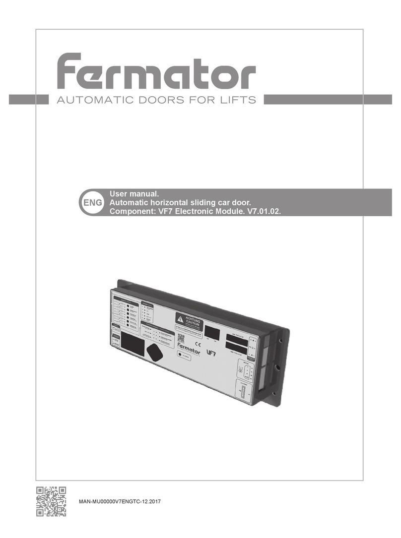
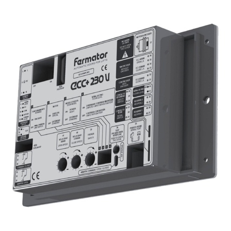
Fermator ECC 230 V User manual

MAN-MUEC00000ENGTC-05.2016
ENG
Assembly manual.
Automatic horizontal sliding car door.
Component: ECC 230 V Electronic Module.
AUTOMATIC DOORS FOR LIFTS

AUTOMATIC DOORS FOR LIFTS
2
ECC 230 V
CONNECTIONS
Motor 24 V DC
3
230 V
24...230 V
24...230 V
1-IN
J209
2-IN
12 V 2,2 Ah
Azul/Blue
Reopening Contact
Rojo/Red
Azul/Blue
Encoder
Final close course contact
Microrruptor
final carrera cerrar
Microrruptor
reapertura contacto
cerrado
Marrón/Brown
Azul/Blue
Marrón/Brown
11
12
8
9
10
L5
N7
PE6
18
19
20
384041 39
1 2 34
1 2 3 4
37
36
35
34
33
29
30
27
28
31
32
22
23
21
25
26
24
0V
14
13
+
12 V
15
16
17
QCI.EC00.C00EE
BATERÍA
BATTERY
FUS 20A SP
FUS 4A SP
SEÑAL
DE PISO
FLOOR
LEVEL
...OK STATUS
NO ABRIR
LA TAPA
DO NOT OPEN
THE COVER
FUERZA
SAFETY
OPEN SPEED
VELOCIDAD
ABRIR
VELOCIDAD
CERRAR
CLOSE SPEED
PULSAR PARA
VERIFICAR
PUSH TO CHECK
THE DOOR
SPECIAL
ESPECIAL
STANDARD
ESTÁNDAR
MOTOR
ENCODER
FINAL CARRERA
LIMIT SWITCH
WORKING
FUNCIONAMIENTO
DOOR MODEL
MODELO PUERTA
HEAVY
PESADA
STANDARD
ESTÁNDAR
FLOOR LEVEL
SEÑAL DE PISO
2 INPUTS / 1 INPUT WITHOUT BATTERY
2 ENTRADAS / 1 ENTRADA SIN BATERÍA
1 INPUT WITH BATTERY
1 ENTRADA CON BATERÍA
ENTRADAS
INPUTS
OUT 24 V
CERRAR
CLOSE
ABRIR
OPEN
0 V
COM
ALIMENT.
SUPPLY
ABIERTA / OPEN
MOTOR & ENCODER
F.C. ABRIR
OPEN L.S.
F.C. CERRAR
CLOSE L.S.
SIN ENCODER
WITHOUT
ENCODER
CON ENCODER
WITH
ENCODER
CONTACTO
SERIE
SERIAL
SWITCH
CONTACTO
SEGURIDAD
SAFETY
SWITCH
REABRIR 2
REOPEN 2
REABRIR 1
REOPEN 1
F.C.CERRAR
CLOSE L.S.
ABIERTA / CERRADA // OPEN / CLOSED

AUTOMATIC DOORS FOR LIFTS
3
ECC 230 V
The unit has to be programmed using the DIP switches on the front of the unit. If any
change is made to any of the above switch selections, the unit must be switched OFF
and ON again to read the new programming.
The switches functions are:
1 Working.
ON: Encoder.
The door movement control will be done using the motor encoder or the motor encoder
and a close limit switch.
OFF: Limit switch.
The door movement control will be done using an open limit switch and a close limit
switch.
2 Motor.
ON: Special Motor.
Different control is applied to perform the door movement with a special motor.
OFF: Standard Motor.
Standard control is applied to perform the door movement.
3 Door model.
ON: Heavy door.
The motor supplies a 30% extra torque to be able to move heavy doors.
OFF: Standard door.
Standard control is applied to perform the door movement.
4 Floor level.
Inputs 12 V battery
ON 2 Inputs
1 Input
OFF
Note: With DIP-switch No. 4 OFF is necessary to install a oor level contact in each oor.
J209 1 & 2 INGRESSI.
1 InPUT (1-IN ).
The door control unit will be controlled by a single input. Any voltage between 24 V DC to
60 V DC or 100 V AC to 230 V AC applied between terminals 10 & 12 will close the doors.
Without input active the door remains opened. Open input is not used.
2 Inputs (2-IN ).
The door control unit will be controlled by two independent inputs. Any voltage between
24 V DC to 60 V DC or 100 V AC to 230 V AC applied between terminals 10 & 12 will
cause the doors to close. And between terminals 8 & 10 will cause the doors to open. In
the absence of a signal, the doors will remain static. If both inputs are applied then the
open signal has priority.
1
O
N
234
O
F
F
PROGRAMMING

AUTOMATIC DOORS FOR LIFTS
4
ECC 230 V
5 / 6 / 7 POWER INPUTS 230 VOLTS SINGLE PHASE AC.
The circuit has been designed to operate on a mains supply of 230 V AC (+10%,-15%, 50
or 60 Hz).
CONTROLS INPUTS
The circuit can work with external voltage inputs or by means a volt free contact input.
8 Open signal.
This signal orders the door to open. The tension to apply could be from 24 V DC to 60
V DC or 100 V AC to 230 V AC, with an external supply between this input and common
(10).
9 0 V.
Opposite pole to 12 V, in the case of using internal VOLTAGE, it should be connected to
the common input.
10 Common.
This input is the reference used for the open and close inputs.
11 12 V.
Isolated 12 V output available to control the door via a voltage free contact. Features are:
a) This supply must only be used for this purpose.
b) This contact must be isolated from any other power supply.
12 Close signal.
This signal is used for ordering to close the door.
13 / 14 Floor level.
This input activates the open movement in emergency rescue mode in case of power
failure, through a 12 V battery to rescue the passengers from the lift. The door only will
open if this signal is bridged (Normally Open).
PROGRAMING
INPUTS
Open
Close
Voltage
OPEN
Voltage
CLOSE
Open
Close
OPEN
CLOSE
EXTERNAL VOLTAGE INPUT VOLT FREE CONTACT INPUT
8
9
10
11
12
8
9
10
11
12
24...230 V
24...230 V
Open
Close
Without Voltage
OPEN
With Voltage
CLOSE
Open
Close
Voltage
OPEN
Voltage
CLOSE
1 INPUT 2 INPUTS
Com
12 V
0 V
8
9
10
11
12
Com
12 V
0 V
8
9
10
11
12
24...230 V
24...230 V
24...230 V
24...230 V

AUTOMATIC DOORS FOR LIFTS
5
ECC 230 V
INPUTS
15 / 16 / 17 Battery.
This input is for connecting a 12 V battery 2,2 Ah to act as external emergency power
supply and allows the opening movement of the door in case of power failure.
Output relay
Output relay have been provided to give continuous information to the main lift controller
concerning the status of the doors.
18 / 19 / 20 Open.
Relay activated when the doors are fully open.
LED INDICATORS:
Ok status.
Red LED indicates proper working conditions.
Depending on how the ECC - 230 V is powered, red LED lights up in different ways:
12 V battery230 V power supplyRed LED
Lighting
Blinking
Single ash
– LED lighting: constantly on.
– LED blinking: iso-phase on and off with a frequency of approximately 5 Hz: on for
approximately 100 ms followed by off for approximately 100 ms.
– LED single ash: one short ash (approximately 100 ms) followed by a long off phase
(approximately 2.250 ms).
21 / 22 / 23 Serial switch.
Connection serial exit-entrance. It must be connected in series with the external lock series.
24 / 25 / 26 Safety switch.
Direct connection between the entrance and the exit without any inuence in the electrical
circuit function.
27 / 28 / 29 / 30
Reopen.
This connections are in serial and when it’s activated the door reopens. It is very useful for
the photocell, the cabin push-button or any other device that initiates the reopening process
when the door starts to close. It does not activate when the door is closed. As it is a serial
connection it is necessary to over-bridge the free one.
20
18
19 OPEN
Indicator states and flash rates
Blinking
Lighting
Single
flash
100
100 2250
ms
ms ms
ms
100
on
on
on
off
off
off

AUTOMATIC DOORS FOR LIFTS
6
ECC 230 V
31 / 32 Limit switch with encoder.
Limit switch connection if used with encoder. With DIP-switch No. 1 ON is necessary to
install a close limit switch.
33 / 34 / 35 / 36
Limit switch without encoder.
Limit switch connection if used without encoder. With DIP-switch No. 1 OFF is necessary
to install an open and close limit switch.
37 Motor and encoder.
Output to the 24 DC motor to control speed and torque. The ECC - 230 V motor controller is
formed by a power stage with a feedback speed control circuit with voltage compensation
and current limiting protections (Imax).
38 Test pushbutton.
Operation of the Test pushbutton will cause a door open or close cycle.
39 Safety.
La velocità di apertura della porta può essere regolata da 100 mm/s no a 300 mm/s.
40 Close speed.
The door closing speed can be independently adjusted from 100 mm/s up to 300 mm/s.
41 Open speed.
The door opening speed can be independently adjusted from 100 mm/s up to 300 mm/s.
42 On / Off switch.
Disconnects the unit from the 230 V AC mains supply.
POWER SUPPLY
• DC voltage range 230 V +10%, -15%. AC/DC.
• Minimum power 83 mA 2,8 W.
• Average power (240 cycles/hour) 0,17 A 14,7 W.
• Maximum power 0,27 A 33,7 W.
PWM REGULATION
• PWM frequency 15KHz.
• Voltage range 0...24 V DC III.
• Maximum output current 2 A.
• Positional control: Quadrature encoder.
MOTOR
• Brushed DC motor
• Voltage supply 24 V.
• Power 7 W.
• Enclosure class IP 20.
• Nominal speed 17 rpm.
REFERENCE DATA
INPUTS

Tecnolama, S.A.
Ctra. Constantí Km 3
43206 REUS (Spain)
Tecnolama, S.A., 2016
Josep Vilà Gomis
Amministrator
AUTOMATIC DOORS FOR LIFTS
7
ECC 230 V
INPUTS
• Impedance 8K2 Ω.
• Voltage 24...230 V AC / DC.
OUTPUTS
• Contacts Switched.
• R. contact 50 mW.
• Swich time 5 ms.
• Output current Máximum: 5 A.
• Voltage 240 V
PERFORMANCE
• Open Speed 100...300 mm/s.
• Close speed 100...300 mm/s.
• Safety force 40...150 N adjustable.
REFERENCE DATA
DECLARATION OF CONFORMITY
Herewith declares that the products mentioned below conform with the following E.U.
council directives:
Norm EN 81-1/2
DIRECTIVE 2006/42/EC (Machinery directive), DIRECTIVE 2014/30/UE
(Electromagnetic compatibility), of the European Parliament and of the Council.
ECC 230 V Electronic Module
(10/31700971_M1)

Tecnolama, S.A.
●
Ctra. Constantí, Km 3
●
43206 REUS (Spain)
●
Tel.: +34 977 774 065
Fax: +34 977 771 615
●
www.fermator.com
●
e-mail: info.es@fermator.com
ATENTION: Any type of modication not reexed in this manual, before testing it should be notied
to our Technical Department.
TECNOLAMA accepts no responsability in the event of any damage produced in the equipment
described in this manual and associated installation if the instructions given have not been followed.
TECNOLAMA reserves the rights to modify the products specications of this technical brochure
without any previous advise.
Table of contents
Other Fermator Control Unit manuals
