High-Flying HF-LPD100 User manual

HF-LPD100 Low Power WiFi Module User Manual
HF-LPD100
802.11a/b/g/n WiFi Module User Manual
V 1.3
Overview of Characteristic
Support IEEE802.11 a/b/g/n Wireless Standards, work in 2.4GHz and 5GHz dual band
Based onAndes Core,160MHz CPU, 192KB RAM, 2MB or 8MB Flash
Support UART Data Communication Interface
Support Work As STA/AP/AP+STA Mode
Support Sniffer Method SmartLink V8 Config
Support SoftAP Method SmartAPLink Config
Support WeChat Airkiss 2.0
Support Wireless and Remote Firmware Upgrade Function
Support Software SDK for Develop
Support Different Antenna Option
HF-LPD100:Internal PCB
High-Flying Electronics Technology Co., Ltd.(www.hi-flying.com)
HF-LPD100


HF-LPD100 Low Power WiFi Module User Manual
HISTORY
Ed. V0.1 08-24-2017 Internal Version.
Ed. V1.0 10-26-2018 Released Version
Ed. V1.1 06-04-2019 Add HF-LPD130 Version
Ed. V1.2 09-29-2019 Add HF-LPD100 external pin antenna
Ed. V1.3 11-13-2019 Update PIN definition.
High-Flying Electronics Technology Co., Ltd.(www.hi-flying.com)

HF-LPD100 Low Power WiFi Module User Manual
1.PRODUCT OVERVIEW
1.1. General Description
The HF-LPD100 support 2.4GHz and 5GHz dual band. It is a fully self-contained small form-factor,
single stream, 802.11a/b/g/n Wi-Fimodule,which provide a wireless interface to any equipment with a
Serial interface for data transfer.HF-LPD100 integrate MAC, baseband processor, RFtransceiver with
power amplifier in hardware and all Wi-Fi protocol and configuration functionality and networking stack,
in embedded firmware to make a fully self-contained 802.11b/g/n Wi-Fi solution for a variety of
applications.
The HF-LPD100 employs the world's lowest power consumption embedded architecture. It has been
optimized for all kinds of client applications in the home automation, smart grid, handheld device,
personal medical application and industrial control that have lower data rates, and transmit or receive
data on an infrequent basis.
1.1.1 Key Application
Remote equipment monitoring
Asset tracking and telemetry
Security
Industrial sensors and controls
Home automation
Medical devices
High-Flying Electronics Technology Co., Ltd.(www.hi-flying.com)

HF-LPD100 Low Power WiFi Module User Manual
1.1.2 Device Paremeters
Table1. HF-LPD100 Module Technical Specifications
Class
Item
Parameters
Wireless
Parameters
Certification
TBD
Wireless standard 2.4GHz:802.11 b/g/n
5GHz:802.11 a /n
Frequency range 2.4G Wi-Fi:2412-2462 MHz
5G Wi-Fi B1: 5180-5240MHz, B4: 5745-5825MHz
2.4G Transmit Power 802.11b:20.76dBm ;802.11g:21.94dBm
802.11n20:20.62dBm;802.11n40:21.10dBm
5G Transmit Power
2.4G Receiver
Sensitivity
802.11b: -87.5 dBm (@11Mbps ,CCK)
802.11g: -73.5 dBm (@54Mbps, OFDM)
802.11n: -72.5 dBm (@HT20, MCS7)
5G Receiver Sensitivity
-73.5dBm (@54Mbps ,OFDM)
-72 dBm (HT20,MCS7)
Antenna PCB antenna
Hardware
Parameters
Data Interface
UART
GPIO,SPI
Operating Voltage
2.1~3.46V
Operating Current
Peak (Continuous TX): 345mA
Average(STA, No data): 44mA
Standby: 1.23mA(Reset set to low)
Operating Temp.
-20
℃
- 85
℃
Storage Temp.
-40
℃
- 125
℃
Density
<85%
Dimensions and Size HF-LPD100: 23.1mm x32.8mm x 3.5mm
Software
Parameters
Network Type
STA/AP/AP+STA
Security Mechanisms
WEP/WPA-PSK/WPA2-PSK
Encryption
WEP64/WEP128/TKIP/AES
Update Firmware
Local Wireless, Remote OTA
Customization
Support SDK for application develop
Network Protocol
IPv4, TCP/UDP/HTTP/TLS(SDK)
User Configuration AT+instruction set. Android/ iOS
SmartLink APP tools
High-Flying Electronics Technology Co., Ltd.(www.hi-flying.com)
802.11a:14.82dBm ;802.11n20:15.31dBm
802.11n40:15.84dBm

HF-LPD100 Low Power WiFi Module User Manual
1.2. Hardware Introduction
HF-LPD100 series Wi-Fi module appearance is as following.
Figure 1. HF-LPD100 Appearance
1.2.1. HF-LPD100 Pins Definition
Figure 2. HF-LPD100 Pins Map
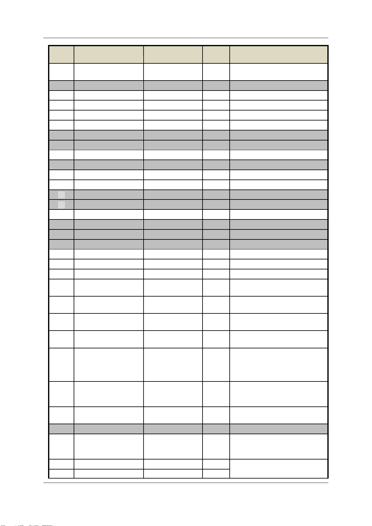
Table2. HF-LPD100 Pins Definition
Pin
Describtion
Net Name
Signal
Type
Comments
High-Flying Electronics Technology Co., Ltd.(www.hi-flying.com)
HF-LPD100 Low Power WiFi Module User Manual
Pin
Describtion
Net Name
Signal
Type
Comments
1,17,18
34,35,37
Ground GND Power
2
NC
3
GPIO00
GPIO00
I/O
PWM0
4
GPIO01
GPIO01
I/O
PWM1
5 USB+ HSDP I/O USB 2.0
6 USB- HSDN I/O USB 2.0
7
TEST
Test only. Leave it unconnected.
8
TEST
Test only. Leave it unconnected.
9,20
+3.3V
DVDD
Power
10
TEST
Test only. Leave it unconnected.
11
GPIO02
GPIO02
I/O
PWM2
12
GPIO04
GPIO04
I/O
PWM4
13
TEST
Test only. Leave it unconnected.
14
TEST
Test only. Leave it unconnected.
15 GPIO03 GPIO03 I/O PWM3
16 TEST Test only. Leave it unconnected.
19
NC
21
NC
22
GPIO11
GPIO11
I/O
23
GPIO05
GPIO05
I/O
24
GPIO09
GPIO09
I/O
25 UART0_TX UART0_TX O3.3V TTL UART0 Output
GPIO07
26 UART1_TX
D
EBUG_UART1_TX
I/O 3.3V TTL Debug UART1_TX
GPIO21, ADC1
27 UART0_RX UART0_RX I3.3V TTL UART0 Input
GPIO06
28
UART1_RX
DEBUG_UART1_RX
I/O
3.3V TTL Debug UART1_RX
GPIO22, ADC0
29 Wi-Fi Status nLink IPD/O “0” – Wi-Fi connect to router
“1” – Wi-Fiunconncted;
Detailed functions see <Notes>
GPIO12
30
Module Boot Up
Indicator
nReady
IPU/O
“0” – Boot-up OK;
“1” – Boot-up No OK;
GPIO08
31
Multi-Function
nReload
IPU/O
Detailed functions see
<Notes> GPIO13
32
N.C
33
Module Reset
RESET
I,PU
“Low” effective reset input.
There is RC reset circuit
internally.
35,37
Ground
GND
Power
Only HF-LPD100-2 has this three
pin for antenna interface
36
ANT
High-Flying Electronics Technology Co., Ltd.(www.hi-flying.com)

HF-LPD100 Low Power WiFi Module User Manual
<Notes>
I — Input;O — Output
PU—Internal Resistor Pull Up; I/O: Digital I/O; Power—Power Supply nReload Pin (Button) function:
1. When this pin is set to “low” during module boot up, the module will enter wireless
firmware and config upgrade mode. This mode is used for customer manufacture.(See
Appendix to download software tools for customer batch configuration and upgrade
firmware during mass production)
2. After module is powered up, short press this button (0.2s < “Low” < 1.5s) and loose to make
the module go into SmartLink V8 config mode, when in SmartLink V8 config mode and short
press this button again to go into SmartAPLink config mode, waiting for APP to set router
SSID and password, config module connect to router. Recommend to use SmartAPLink
method config.
See Appendix to download SmartLink V8 and SmartAPLink APP
3. After module is powered up, long press this button ( “Low” > 4s ) and loose to make the
module recover to factory setting.
High-Flying strongly suggest customer fan out this pin to connector or button for
“Manufacture” upgrade or “ SmartLink” application.
nReady Pin (LED) function(Low effective):
1. OS initial finished indicator. Only after this pin output low, can the UART function be used.
nLink Pin (LED) function(Low effective):
1. At wireless firmware and config upgrade mode , this LED used to indicate configure and
upgrade status.
2. At “SmartLink” config mode, this LED is used to indicate APP to finish setting.
3. At normal mode, it’s Wi-Fi link status indicator. Output Low when STA mode connect to
router AP or other STA connect to it when in AP mode.
High-Flying strongly suggest customer fan out this pin to LED.
UART1 Debug :
1. Is used fordebug log
High-Flying Electronics Technology Co., Ltd.(www.hi-flying.com)

HF-LPD100 Low Power WiFi Module User Manual
Table4. Power Supply & Power Consumption:
Parameter Condition Min. Typ. Max. Unit
Operating Supply voltage 2.1 3.3 3.46 V
Supply current, peak Continuous Tx 260 mA
Supply current, STA No data transfer 27 mA
Supply current, STA Continuous data transfer 35 mA
Supply current, AP 80 mA
GPIO sink current GND+0.5V 20 mA
GPIO pull current VCC-0.5V 20 mA
High-Flying Electronics Technology Co., Ltd.(www.hi-flying.com)
1.2.2. Electrical Characteristics
Table3. Absolute Maximum Ratings:
Parameter Condition Min. Typ. Max. Unit
Work temperature range -20 85 °C
Maximum soldering temperature IPC/JEDEC J-STD-020 260 °C
ESD (Human Body Model HBM) TAMB=25°C 2.5 KV
ESD (MM) TAMB=25°C 0.25 KV
HF-LPD100 Low Power WiFi Module User Manual
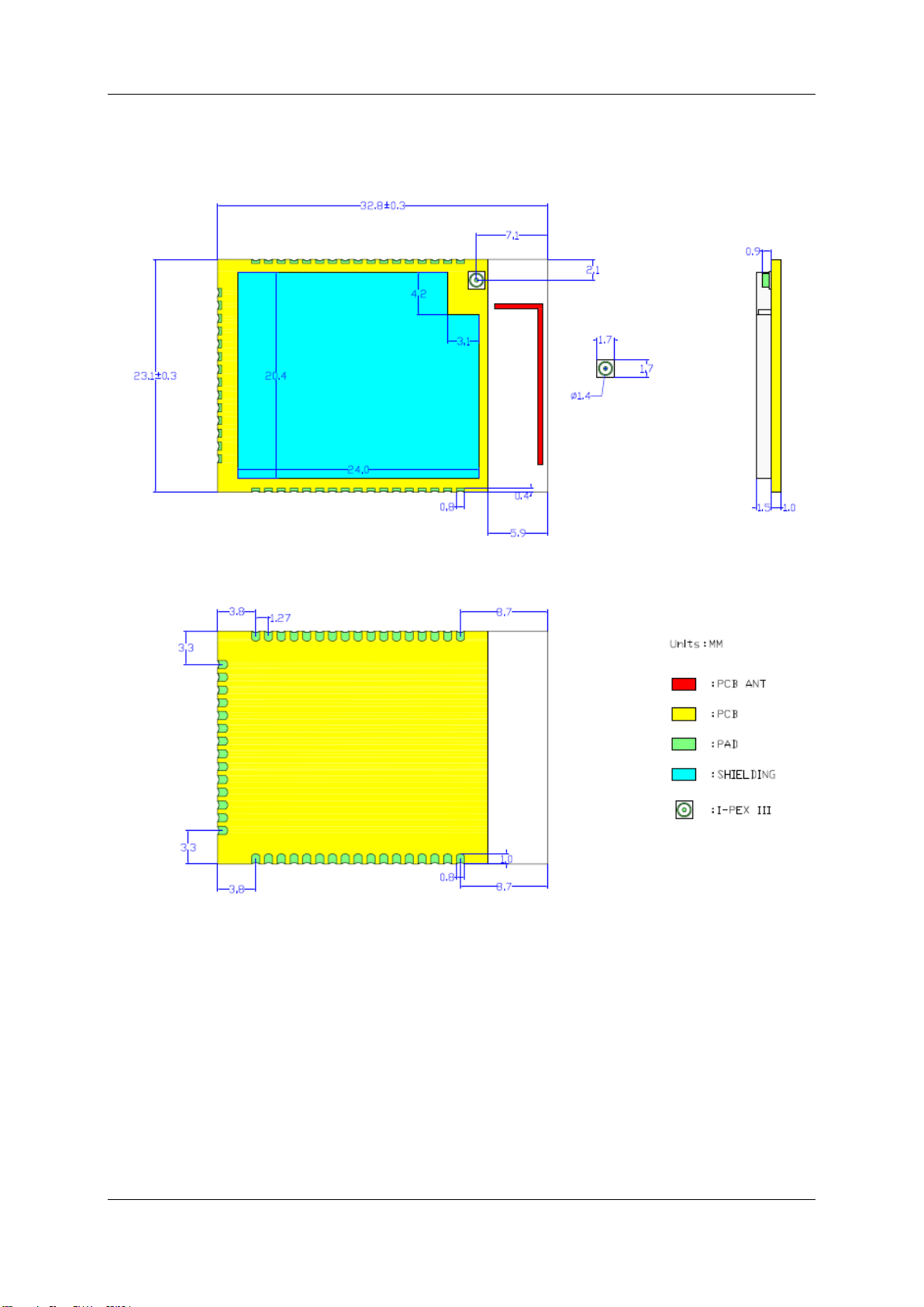
1.2.3. HF-LPD100 Mechanical Size
HF-LPD100 modules physical size (Unit: mm)as follows:
Figure 3. HF-LPD100-1 and -0 Mechanical Dimension
1.2.4. HF-LPD100 On-board PCB Antenna
HF-LPD100 module support internal on-board PCB antenna option. When customer select internal
antenna, you shall comply with following antenna design rules and module location suggestions:
For customer PCB, RED color region (8.3x18.4mm) can’t put componet or paste GND net;
Antenna must away from metal or high components at least 10mm;
Antenna can’t be shielded by any metal enclosure;
High-Flying Electronics Technology Co., Ltd.(www.hi-flying.com)

HF-LPD100 Low Power WiFi Module User Manual
Figure 4. Suggested Module Placement Region
High-Flying suggest module better locate in following region at customer board, which to reduce the
effect to antenna and wireless signal, and better consult High-Flying technical people when you
structure your module placement and PCB layout.
1.2.5.Evaluation Kit
High-Flying provides the evaluation kit to promote user to familiar the product and develop the detailed
application. The evaluation kit shown as below, user can connect to HF-LPD100 series module with
the RS-232 UART, USB (Internal USB to UART convetor) or Wireless interface to configure the
parameters, manage the module or do the some functional tests.
High-Flying Electronics Technology Co., Ltd.(www.hi-flying.com)
Figure 5. HF-LPD100 EVK
Notes: User need download USB to UART port driver from High-Flying web or contact with technical
support people for more detail.
HF-LPD100 Low Power WiFi Module User Manual
High-Flying Electronics Technology Co., Ltd.(www.hi-flying.com)
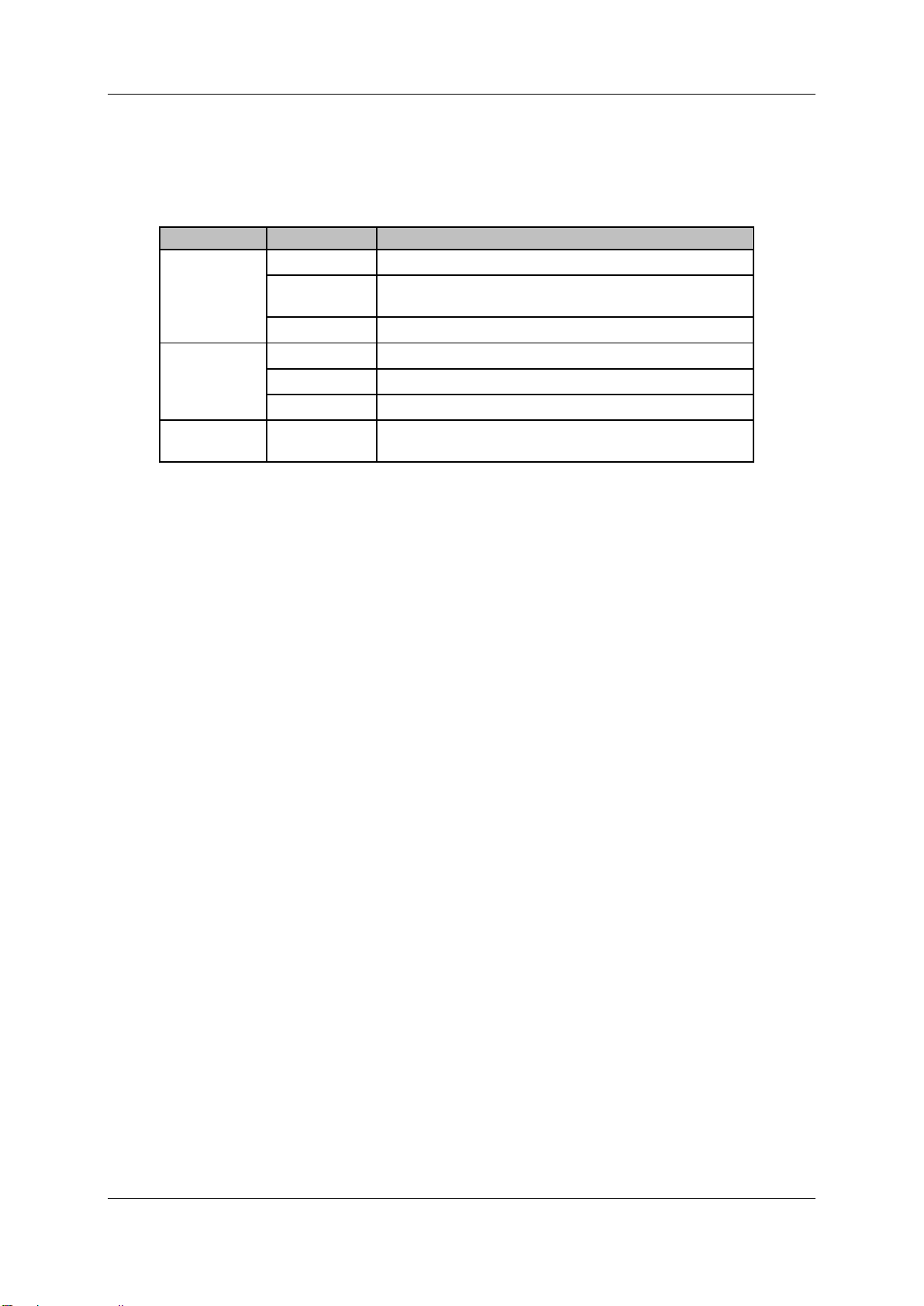
The external interface description for evaluation kit as follows:
Table6. HF-LPD100 Evaluation Kit Interface Description
Function Name Description
External
Interface RS232 Main data/command RS-232 interface
USB USB to UART interface, can be used for debug
UART log
DC5V DC jack for power in, 5~9V input.
LED Power Power LED
Ready nReady LED
Link nLink LED
Button nReload Smartlink and Restore factory default configuration.
See more for PIN Definition
HF-LPD100 Low Power WiFi Module User Manual
2.PACKAGE INFORMATION
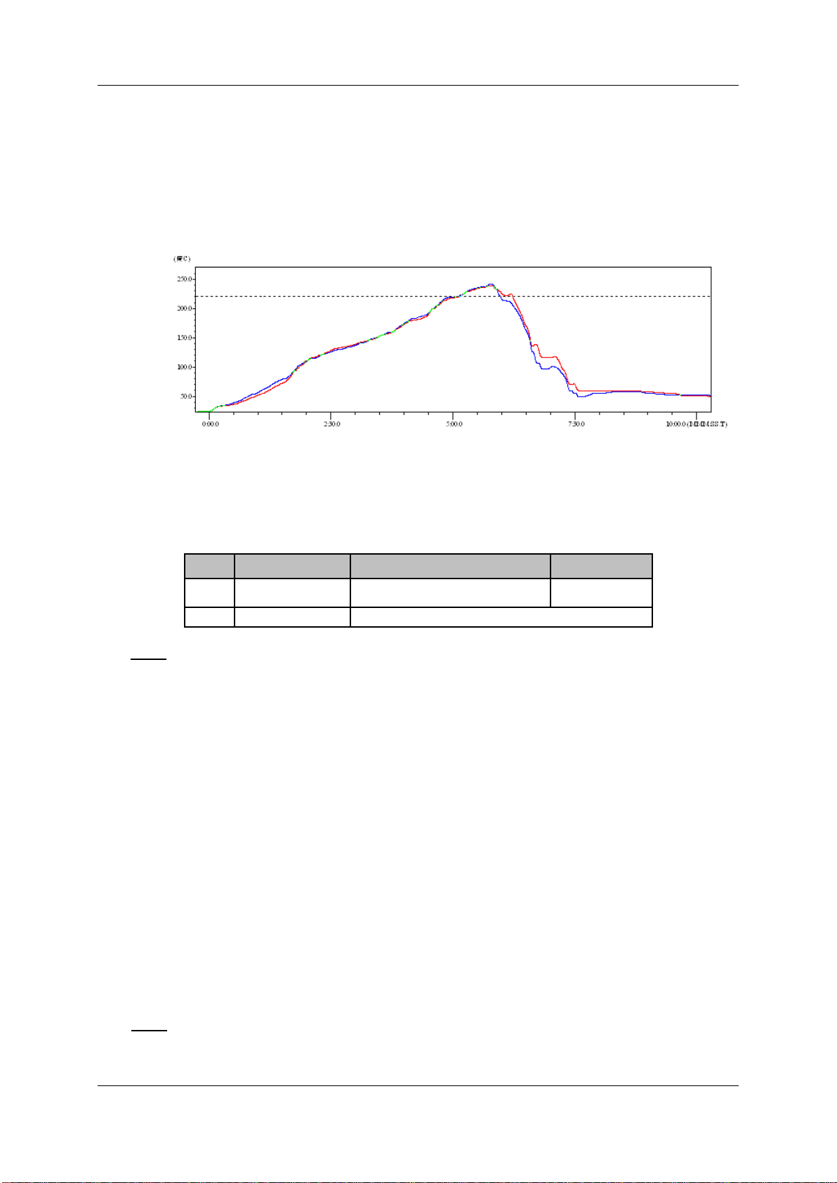
2.1. Recommended Reflow Profile
Figure 7. Reflow Soldering Profile
Table7. Reflow Soldering Parameter
Note: 1. Recommend to supply N2 for reflow oven.
2. N2 atmosphere during reflow (O2<300ppm)
2.2. Device Handling Instruction (Module IC SMT Preparation)
1. Shelf life in sealed bag: 12 months, at <30℃ and <60% relative humidity
2. After bag is opened, devices that will be re-baked required after last baked with window time
168 hours.
3. Recommend to oven bake with N2 supplied
NO. Item Temperature (Degree) Time(Sec)
1 Reflow Time Time of above 220 35~55 sec
2 Peak-Temp 260 max
High-Flying Electronics Technology Co., Ltd.(www.hi-flying.com)
4. Recommend end to reflow oven with N2 supplied
5. Baked required with 24 hours at 125+-5. 0℃ before rework process
6. Recommend to store at ≦10% RH with vacuum packing
7. If SMT process needs twice reflow:
(1) Top side SMT and reflow (2) Bottom side SMT and reflow
Case 1: Wifi module mounted on top side. Need to bake when bottom side process over 168
hours window time, no need to bake within 168 hours
Case 2: Wifi module mounted on bottom side, follow normal bake rule before process
Note: Window time means from last bake end to next reflow start that has 168 hours space.


OEM Guidance
1. Applicable FCC rules
2. The specific operational use conditions
This module can be used in IoT devices. The input voltage to the module is
nominally 2.1~3.46V DC. The operational ambient temperature of the module is
–40 °C ~ 65 °C. Only the embedded PCB antenna is allowed. Any other
external antenna is prohibited.
3. Limited module procedures
N/A
4. Trace antenna design
N/A
5. RF exposure considerations
The equipment complies with FCC radiation exposure limits set forth for an
uncontrolled environment. This equipment should be installed and operated with
minimum distance 20cm between the radiator and your body. If the equipment
built into a host as a portable usage, the additional RF exposure evaluation may
be required as specified by 2.1093.
6. Antenna
Antenna type: PCB antenna Peak gain: 0dBi
7. Label and compliance information
An exterior label on OEM’s end product can use wording such as the following:
“Contains Transmitter Module FCC ID: 2ACSVHF-LPD100” or
“Contains FCC ID: 2ACSVHF-LPD100.”
OEM Guidance
1. Applicable FCC rules
This module is granted by Single Modular Approval. It complies to
the requirements of FCC part 15.247 and 15.407

8. Information on test modes and additional testing requirements
a)The modular transmitter has been fully tested by the module grantee on the required
number of channels,modulation types, and modes, it should not be necessary for the host
installer to re-test all the available transmitter modes or settings. It is recommended that the
host product manufacturer, installing the modular transmitter,perform some investigative
measurements to confirm that the resulting composite system does not exceed the spurious
emissions limits or band edge limits (e.g., where a different antenna may be causing
additional emissions).
b)The testing should check for emissions that may occur due to the intermixing of emissions
with the other transmitters, digital circuitry, or due to physical properties of the host product
(enclosure). This investigation is especially important when integrating multiple modular
transmitters where the certification is based on testing each of them in a stand-alone
configuration. It is important to note that host product manufacturers should not assume that
because the modular transmitter is certified that they do not have any responsibility for final
product compliance.
c)If the investigation indicates a compliance concern the host product manufacturer is
obligated to mitigate the issue. Host products using a modular transmitter are subject to all
the applicable individual technical rules as well as to the general conditions of operation in
Sections 15.5, 15.15, and 15.29 to not cause interference. The operator of the host product
will be obligated to stop operating the device until the interference have been corrected .
9. Additional testing, Part 15 Sub part B disclaimer The final host / module combination
need to be evaluated against the FCC Part 15B criteria for unintentional radiators in order
to be properly authorized for operation as a Part 15 digital device.
The host integrator installing this module into their product must ensure that the final
composite product complies with the FCC requirements by a technical assessment or
evaluation to the FCC rules, including the transmitter operation and should refer to guidance
in KDB 996369. For host products with certified modular transmitter, the frequency range of
investigation of the composite system is specified by rule in Sections 15.33(a)(1) through
(a)(3), or the range applicable to the digital device, as shown in Section 15.33(b)(1),
whichever is the higher frequency range of investigation When testing the host product, all
the transmitters must be operating.The transmitters can be enabled by using publicly-
available drivers and turned on, so the transmitters are active. In certain conditions it might
be appropriate to use a technology-specific call box (test set) where accessory 50 devices or
drivers are not available. When testing for emissions from the unintentional radiator, the
transmitter shall be placed in the receive mode or idle mode, if possible. If receive mode only
is not possible then, the radio shall be passive (preferred) and/or active scanning. In these
cases, this would need to enable activity on the communication BUS (i.e., PCIe, SDIO, USB)
to ensure the unintentional radiator circuitry is enabled. Testing laboratories may need to add
attenuation or filters depending on the signal strength of any active beacons (if applicable)
from the enabled radio(s). See ANSI C63.4, ANSI C63.10 and ANSI C63.26 for further
general testing details.
The product under test is set into a link/association with a partnering device, as per the
normal intended use of the product. To ease testing, the product under test is set to transmit
at a high duty cycle, such as by sending a file or streaming some media content.
FCC Warning:
Any Changes or modifications not expressly approved by the party responsible for compliance
could void the user’s authority to operate the equipment. This device complies with part 15 of the
FCC Rules. Operation is subject to the following two conditions: (1) This device may not cause
harmful interference, and (2) This device must accept any interference received, including
interference that may cause undesired operation
Table of contents
Other High-Flying Wireless Router manuals


