High Torque Hughes 500 Instruction Manual

Building instructions for the Hughes 500 for ECO8 & Logo 10
Congratulations on your purchase of this Kit.
With very little trouble you can convert your model into a beautiful
Hughes 500.
We do not recommend that you use any activator/accelerator with
the adhesive on this material. The heat generated by the activator
has a tendency to distort the material.
t is advisable to test all of your adhesives and paint/lacquers on a
piece of the material supplied before use.
The fuselage halves have been pre trimmed and only require to be
de burred, before joining together.
From the piece of material supplied, cut small join plates as shown
and hold in place using sellotape. The intervals are shown in the
next photograph.
Glue these plates in place using a small drop of viscous (thick)
superglue.
When dry the sellotape can be removed.
The two halves can now be joined together at regular points using
superglue, a rod should be used to exert any pressure required
from the inside on each joint. When set, run around the join with
thin superglue, and smooth the join with a palette knife.
H001 Page 1 of 4

The nose section consists of four separate pieces, a mounting
piece, shown in white in the illustration, two side windows and a
front window.
The mounting piece should be trimmed and smoothed along its
marked lines. The windows should be trimmed at approximately
5-10mm outside their markings to allow an overlap for glueing in
place. This area should be roughened with sandpaper in
preparation for glueing.
DO NOT GLUE THE W NDOWS N PLACE AT TH S PO NT.
A balsa chassis mounting board is provided, this is marked with an
outline of where to cut, and spot points for the centres of the skid
legs, there is also a line at the point where the rear-mounting latch
is to be positioned.
Remove the hood from your ECO8 and dismantle the skids. nto the
rear lower skid mounting holes insert the 2mm screw provided pass
it through the plastic tube, also provided, and apply the 2mm nut,
secure with superglue, this acts as the mounting rod at the Latch.
A latch should now be made from plywood similar to the drawing,
this should be glued onto the mounting plate to act, together with
the 2mm screw, to retain the rear of the ECO8 mechanism
Then manufacture a small traverse plate from plywood to be placed
across the rods at the front of the mechanism, and using the two
impact nuts and 3mm socket screws, to act as retainers at the front
end. The mechanism can then in future be removed by releasing
these two screws
At the points marked on the body for the skid legs, glue thick pieces
of balsa into position, inside the fuselage. When set, these should
be drilled at a slightly smaller diameter to the skid legs in order that
the fit be firm and secure.
Mount the ECO8 mechanism onto the mounting board, and then
with the tail rotor removed, insert the mechanism together with the
tail pipe into the fuselage.
When correctly positioned, glue the board in position. A short length
of balsa can be glued under each side as reinforcement.
Now prepare the skid legs, cut them to length, and at the end that
will take the skids, insert and glue in place a 10mm length of the
birch rod provided. When set, drill a small pilot hole to take the
screws provided to retain the skids. Glue the skid legs in place,
both at the chassis board, and where the legs pass through the
fuselage.
Drill and countersink the holes for the skid retaining screws, and
mount the skids on the skid legs.
Application of heat allows the forming of the front end of the skids.
H001 Page 2 of 4
Traverse
plate
Latch
Prepare the front mounting section by fixing 5 of the magnets
provided, in the positions shown, two on the RH side, two on the LH
side, one in the lower centre, utilize small balsa pieces to mount the
magnets. Rough the faces of the magnets before glueing.
Align the mounting piece with the fuselage and mark the points at
which the internal magnets are to be fixed.
Glue in place the internal magnets on their balsa mounts.
When the glue is dry, allow the mounting section to jump into place
on the magnets. Now the front window can be glued in place. This
should be done from the inside with the mounting section in place
to avoid any distortion. When dry, remove the front section and
glue the side windows in place.
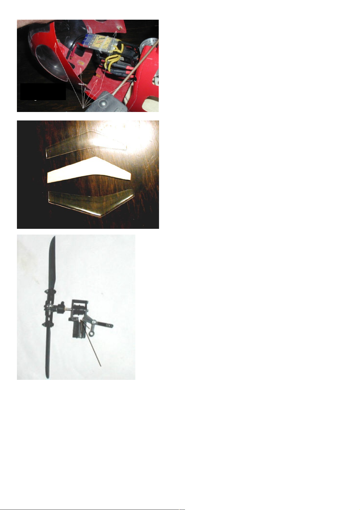
Cut out the parts for the vertical stabiliser, and a section of balsa to
reinforce the fin, fit it between the two pieces, glue together.
Cut the horizontal tail fin and the small vertical fins from balsa, and
assemble all of these pieces together with superglue.
The completed tail fin unit can be mounted in its original place on
the tail tube, using the original screw.
The tail rotor gearbox frame should be cut out at the point shown
this will allow for easier assembly of the drive belt.
H001 Page 3 of 4
Positions for
balsa & magnets

Before painting your model, the area to be painted should be
roughened with 600-1200 grade sand paper to provide a good “key”
for the paint to bond with the Pet-G material.
f there are any holes or gaps these can be filled with polyester
putty and smoothed to give a good finish.
Spray painting is best done with a lacquer that does not contain
solvents, these take a long time to dry. For the best results and
quick drying, the room should ideally be at 25deg C, and the spray
can also heated to 25deg C. For best results a number of thin coats
should be sprayed.
Do not hang the fuselage vertically when painting, place it on a rod,
this reduces the chances of the paint running.
To find different liveries used on the Hughes 500 series of
helicopter, search in Google under “pictures” and search word
“Hughes 500”, a number of different colour finishes will be
displayed.
H001 Page 4 of 4
Thank you for your purchase.
We are sure that you will get a lot of enjoyment from your Hughes 500.
Table of contents
Popular Toy manuals by other brands


Nexa
Nexa MACCHI MC 205 instruction manual

Fisher-Price
Fisher-Price Voice Tech Rescue Heroes Aquatic Rescue Command Center... instruction manual

Hasbro
Hasbro Play-Doh Frosting Fun Bakery manual

Nerf
Nerf MINECRAFT SABREWING F4733 quick start guide

REVELL
REVELL KIT 8337 Assembly manual

Amewi
Amewi AMXFlight D0-27 manual