manuals.online logo
Brands
  1. Home
  2. •
  3. Brands
  4. •
  5. Highcross
  6. •
  7. Control Unit
  8. •
  9. Highcross ECM-RL12LVD User manual

Highcross ECM-RL12LVD User manual

©HighCross Ltd.
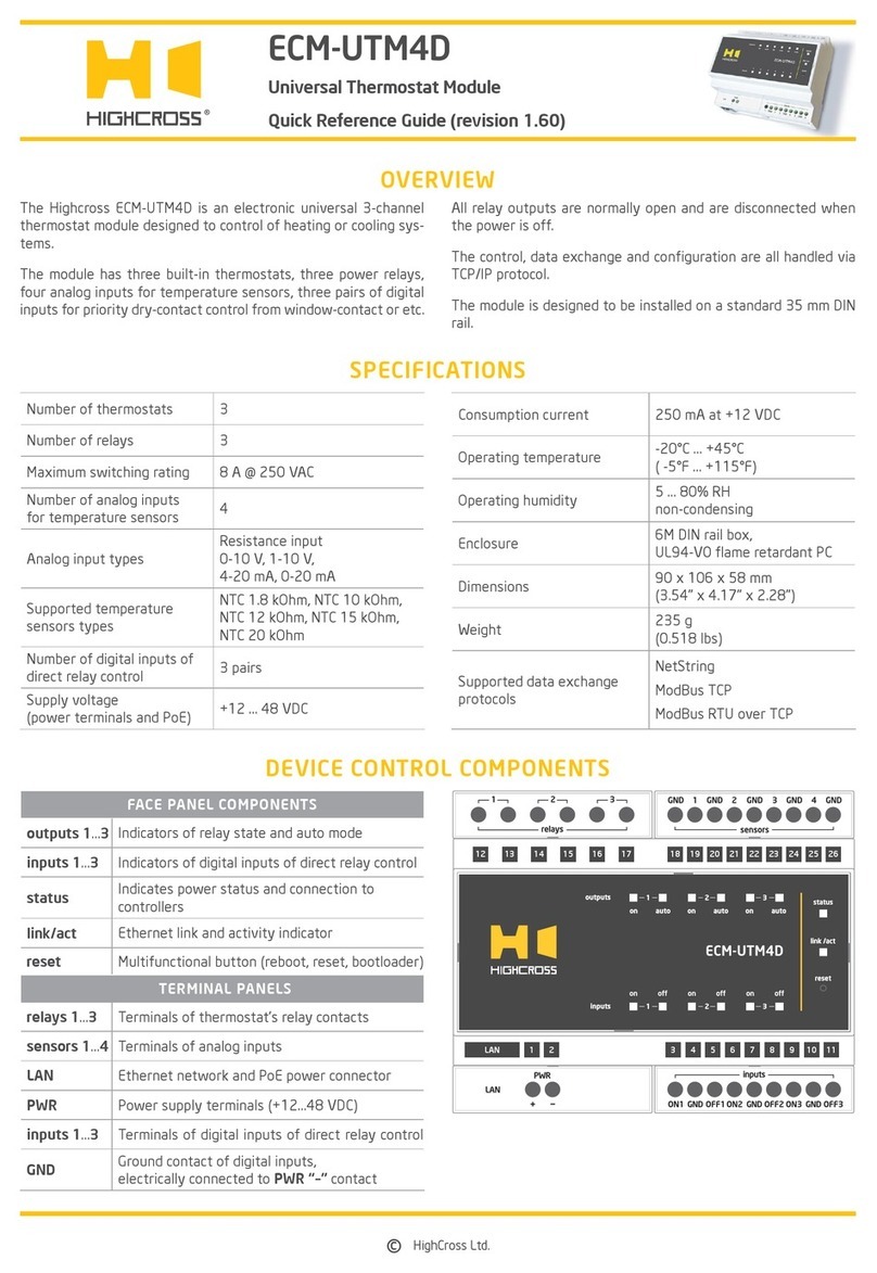
OVERVIEW
DEVICE CONTROL COMPONENTS
Number of relay outputs 12
Maximum switching current
of relay output 1 A
Maximum switching voltage
of relay output 30 VDC or 60 VAC
Supply voltage range 12–24 VDC via power terminals
48 VDC via PoE port
Consumption current 250 mA @ 12 VDC
Enclosure 5M DIN rail box,
UL94-V0 ame retardant PC
FACE PANEL COMPONENTS
1–12 Activity indicators of channels 1–12
status Indicates power status and connection to
controllers
link/act Ethernet link and activity indicator
reset Multifunctional button (reboot, reset, boot-
loader)
TERMINAL PANELS
LAN Ethernet network and PoE power connector
relays 1–12 Terminals of relay contacts
PWR Power supply terminals (12–24 VDC)
Operating temperature -20° C to 45° C
-5° F to 115° F
Operating humidity 5 to 80% RH
non-condensing
Dimensions (HWD) 90 mm x 88 mm x 58 mm
3.54” x 3.46” x 2.28”
Weight 190 g
0.42 lbs
Supported data exchange
protocols
NetString
ModBus TCP
ModBus RTU over TCP
ECM-RL12LVD
Low-Voltage Relay Module
Quick Reference Guide (revision 1.40 for H/W Rev.B)
15 16 17 18 19 20 21 22 23 24 25 26LAN
1 2 3 4 5 6 7 8 9 10 11 12 13 14
SPECIFICATIONS
The Highcross ECM-RL12LVD module has twelve low-voltage low-
current signal relay outputs for providing a potential-free output
contact.
All channels are normally open and are disconnected when the
power is off.
The control, data exchange and conguration are all handled via
TCP/IP protocol.
The module is designed to be installed on a standard 35 mm DIN
rail.
ECM-RL12LVD | Low-Voltage Relay Module | revision 1.40
©HighCross Ltd.
LED “status” indicates the power connection
and connection status with controllers
Off No power connected
Blink
(1 Hz) No connection with external controllers
Fast blink
(4 Hz) The device is in bootloader mode
On Connected to external controllers
LED “link“ indicates Ethernet network
link and activity
Off No connection to Ethernet network
Blink Connected to Ethernet network
Receiving Ethernet data packets
On Connected to Ethernet network
No network activity
LEDs “1–12“ display status of outputs
Off Output is off
On Output is on
Multifunctional button “reset“
To reboot the device push the button for 1 second
To reset the device to factory defaults push and hold the
button for 5 seconds.
IP–address will be set to 10.0.1.101, subnet mask - to
255.255.255.0. All other settings will be set to default values
For rmware update, power off the device, push and hold
the button and power the device on. Release the button after
the LED “status” will start to blink fast.
The network settings of the device started in bootloader
mode are: IP–address – 10.0.1.101, subnet mask –
255.255.255.0
The PWR “+” and “–” terminals are designed to power the device
12–24 VDC if connected Ethernet switch has no PoE support.
Terminals 1–12 (pairs of K1A–K1B to K12A–K12B) of channels
1–12 are designed to connect wires from controlled devices.
Warning: To prevent damaging of the relay outputs be sure that
cos φof switched load is bigger than 0.4.
SETUP AND CONFIGURATION
The conguration of the module is handled via web-interface.
To start working with the device:
• Connect the device to the Ethernet switch. If the switch has
no PoE support, connect the power 12–24 VDC to the PWR
terminal
• Ensure that your computer can connect to the network address
10.0.1.101 or set the TCP/IP settings of active network adap-
tor to: IP address –
10.0.1.100
, subnet mask –
255.255.255.0
• Enter 10.0.1.101 in address bar of your web-browser
• Enter: login – root, password – root
• Congure the device settings
The web-interface contains the next web-pages:
Home Displays the hardware revision and the
rmware version
Settings Network settings, type of data exchange
protocol, outputs settings
Control Displays current state of outputs.
Control of outputs
Status Displays current TCP/IP connections and device
uptime info
For further information refer to www.highcross.pro


Other Highcross Control Unit manuals

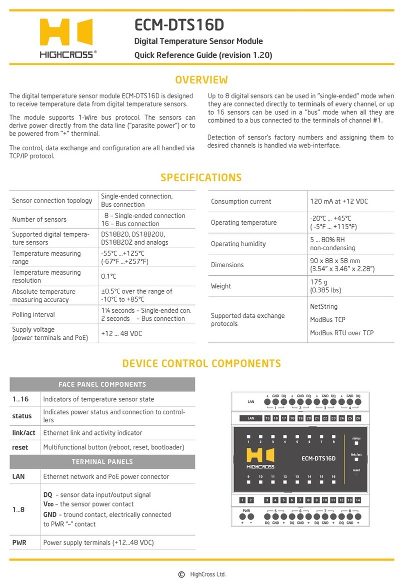
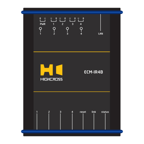
Highcross ECM-IR4B User manual

Highcross

Highcross ECM-IR4B User manual

Highcross ECM-DTS16D User manual

Highcross

Highcross ECM-DTS16D User manual

Highcross ECM-UTM4D User manual

Highcross

Highcross ECM-UTM4D User manual

Highcross ECM-RS2D User manual

Highcross

Highcross ECM-RS2D User manual

Highcross ECM-RS2B User manual

Highcross

Highcross ECM-RS2B User manual

Popular Control Unit manuals by other brands

DeZurik BHP manual

DeZurik

DeZurik BHP manual

Acromag BusWorks XT Series user manual

Acromag

Acromag BusWorks XT Series user manual

Siemens HARS-T03 Series manual

Siemens

Siemens HARS-T03 Series manual

Silis Electronique CHAUFFAGE SMS V2 manual

Silis Electronique

Silis Electronique CHAUFFAGE SMS V2 manual

Emerson Tartarini PRX Series manual

Emerson

Emerson Tartarini PRX Series manual

ADTRAN Job Aid+ 1442707G3 manual

ADTRAN

ADTRAN Job Aid+ 1442707G3 manual

Dikkan DN15 operating instructions

Dikkan

Dikkan DN15 operating instructions

McIntosh TM1 Dealer installation guide

McIntosh

McIntosh TM1 Dealer installation guide

SCHUNK HLM Series Assembly and operating manual

SCHUNK

SCHUNK HLM Series Assembly and operating manual

Pilz PNOZ m EF Multi Link operating manual

Pilz

Pilz PNOZ m EF Multi Link operating manual

ELPRO 505U user manual

ELPRO

ELPRO 505U user manual

Fireye D30 Series manual

Fireye

Fireye D30 Series manual

Audiophonics Up2Stream WA31 user manual

Audiophonics

Audiophonics Up2Stream WA31 user manual

Datamax I-Class Installation and operating instructions

Datamax

Datamax I-Class Installation and operating instructions

WAGO 750-535/040-000 manual

WAGO

WAGO 750-535/040-000 manual

Banner MM-TA-12B instruction manual

Banner

Banner MM-TA-12B instruction manual

EOS ECON D4 Assembly and operation instruction

EOS

EOS ECON D4 Assembly and operation instruction

Brähler Systems DIGIMIC DCen mini MkII quick guide

Brähler Systems

Brähler Systems DIGIMIC DCen mini MkII quick guide

manuals.online logo
manuals.online logoBrands
  • About & Mission
  • Contact us
  • Privacy Policy
  • Terms and Conditions

Copyright 2025 Manuals.Online. All Rights Reserved.