Highland Tank R-HT Series User manual

www.highlandtank.com • 1
User’s Manual
Installation
Operation
Maintenance
Carefully read and follow the instructions in this manual.
WASTEWATER TREATMENT SYSTEMS
RECTANGULAR
OIL/WATER
SEPARATORS Aboveground
HT, HTC, UL-SU2215
Single-wall & Double-wall
Series G, J, S & TF
Unmatched Quality & Service Proudly made
in America

2 • www.highlandtank.com
Warning and Disclaimer
This manual is intended for use only by persons knowledgeable
and experienced in aboveground oil/water separator installation,
operation and maintenance. This manual provides general guidance,
and conditions at your site may render inapplicable some or all of
the guidance. If you are uncertain, or require clarication or further
instruction, please contact Highland Tank prior to commencing any
installation, operation or maintenance procedure. You are solely
responsible for compliance with all federal, state and local laws,
regulations and ordinances applicable to your installation and
operation. Highland Tank disclaims all liability related to any misuse
of the oil/water separator or failure to follow all guidance and
instruction provided by Highland Tank.

www.highlandtank.com • 3
Installation 8
Piping - Inlet, Outlet & Vent 15
Start-up 23
Operation 25
Maintenance 27
Troubleshooting Guide 36
OWS Reference Drawing 38
Appendix - A - Sample Inspection and Maintenance Log
Thank you for purchasing a Highland Tank Oil/Water Separator -
the leading high-performance separator in the industry.
The purpose of this manual is to provide detailed information
on the installation, venting, startup, operation, maintenance
and trouble-shooting of Highland Tank’s Oil/Water Separator.
These instructions should be used in conjunction with any
and all other applicable installation instructions, e.g.:
• Petroleum Equipment Institute Installation of Aboveground
Liquid Storage Systems, PEI/RP200.
• Any and all applicable federal, state and local codes. Always
check with Authority Having Jurisdiction.
Note: This manual is based on standard OWS congurations.
Other custom congurations are available. Verify the supplied
conguration prior to installation and testing.
Abbreviations used:
OWS – Oil/Water Separator
AHJ – Authority Having Jurisdiction
PSIG – Pounds per square inch gauge
OSHA – Occupational Safety and Health Administration
Contents
Introduction

4 • www.highlandtank.com
Important points to consider prior to installation, operation and maintenance
of the OWS:
Carefully read and follow instructions in this manual. Local codes and ordinances may apply.
Check with local AHJ prior to installation of OWS.
• Ensure adequate site space - many of our products are delivered on a 75 foot long
tractor-trailer. Allow space for unloading, positioning and temporary storage if applicable.
• Ensure the crane has adequate lifting capacity and clearance - have operator check site for
clearances (overhead, turning, etc.). Spreader bars may be required for larger OWSs.
• Ensure that installation staff have proper knowledge of proper procedures and inherent dangers
associated with OWS installation for the storage of ammable and combustible liquids. Reliance
on skilled, professional installation staff, can help avoid system failures and accidents.
• Special permits may be required for weight, size, etc. by local code or ordinance.
• Barricade the OWS installation area until job is complete.
• Conrm inlet and outlet piping elevations - check/recheck approval drawing and site plan
when OWS arrives.
• If an OWS hold-down system is required, make sure predetermined system components are
at the site prior to OWS installation. Check anchor bolt locations if applicable.
• The amount of debris, such as sand, gravel, dirt, leaves, wood, rags, etc., permitted to enter
the OWS must be minimized for maximum effectiveness. Installation of an appropriately sized
Collection Catch Basin or other similar device upstream of the OWS is recommended.
• For OWS with integral sludge hoppers, it is recommended that a shut-off valve be installed
at the drain nozzle for periodic sludge removal.
• Detergents and solvents must not enter the OWS. The OWS will not remove chemical
emulsions or dissolved hydrocarbons, and their presence retards the recovery of oils that
would otherwise be separated.
• Never enter the OWS or any of its enclosed spaces without proper conned space entry
training and approved equipment. See OSHA, Regulations for Permit-Required Conned
Spaces 29 C.F.R. § 1910.146.
• The OWS must be kept from freezing at all times. If necessary, a thermostatically controlled
steam or electric heating device may be installed.

www.highlandtank.com • 5
Important points to consider continued:
• IMPORTANT: DO NOT modify OWS structure in any way. DO NOT weld on OWS.
• This is a stationary OWS. DO NOT use for transport of any product over roads and highways.
• Wastewater containing high concentrations of dissolved solids (such as untreated sanitary
sewage) must be excluded due to its emulsifying tendency. Wastewater, which exhibits high
Biological Oxygen Demand, Chemical Oxygen Demand, and Total Suspended Solids may
require additional treatment beyond that of the OWS.
• The OWS will not remove chemical or physical emulsions, dissolved hydrocarbons, solvents
or Volatile Organic Compounds. Installation of an appropriately sized Advanced Hydrocarbon
Filtration System (brochure HT-2502) is recommended for treatment of wastewater contaminated
with these pollutants.
• Waste oils, such as automobile and truck crank case oil, should not be intentionally
drained into the OWS. Filling the OWS with waste oils adversely affects OWS performance.
Waste oil should be dumped into a waste holding tank for proper disposal.
• The OWS needs to be maintained to remain as free of accumulated oil and sediment as
possible. Suction removal of waste, as needed, is the best and recommended method
of maintenance.
• The location of your OWS should be in an area with sufcient truck access for waste removal.
• An absence of gravity ow to the OWS will necessitate wastewater pumping. Pumping
should be restricted to the clean water, efuent end of the OWS where possible. If pumping
cannot be avoided at the inuent end, it may mix the oil and water, increasing the emulsied
and dissolved oil content and may cause separation failure. If a pump is installed upstream of
the OWS, it must be a positive displacement pump (e.g. progressive cavity, diaphragm, sliding
shoe), set at minimum ow rate/RPM and installed as far upstream as possible to minimize
oil/water mixing.
• Piping should be designed to minimize turbulence and promote laminar ow.
• Complete the OWS Installation Checklist and Start-up Report (Form # HT-9060). A copy of
the completed form should be retained by the OWS owner and/or installation contractor.
• OWS must be lled with clean water before introducing any wastewater. Filling should only
be done after OWS has been leveled and anchored in nal installation location.

6 • www.highlandtank.com
Highland Tank’s OWS is a wastewater treatment tank used to
intercept and collect free-oil, raw petroleum hydrocarbons, grease
and oily-coated solids from a wastewater stream.
They are typically required in all facilities that conduct washing,
servicing, repairing, maintenance or storage of motor vehicles,
car washes, commercial vehicle garages, repair facilities, service
stations and similar sites where oil or ammable liquids may be
introduced into a sewer system.
Designed to accept gravity ow, the OWS volume, retention time
and use of coalescing elements permit these contaminants to
separate from the water due to their differences in specic gravity.
The OWS contains multiple chambers where oils separate
and oat to the surface, while sand and grit settle to the bottom.
Free-oating oils and oatable oily-coated solids accumulate in the
OWS until they are pumped out. The clearer water beneath the
separated wastes ows downward and then is transferred to the
clearwell chamber through the PVC riser pipes. The clearest water
exits the OWS via the downcomer pipe where it is discharged from
the nal OWS.
OWS sizing and construction conforms to most plumbing
codes and the efuent discharge meets or exceeds many municipal
industrial sewer pretreatment regulations. Nonetheless, you must
conrm all code and regulatory requirements with your AHJ prior
to and during installation of the OWS. To view an animated
simulation of the OWS operation, go to www.highlandtank.com
Standard OWS
Description

www.highlandtank.com • 7
Aboveground installation
avoids costly excavation
Electronic oil level sensor
can signal remote alarm
panel of high oil condition
Removable, top panels
for easy access and
maintenance
High-performance
wastewater treatment
at varying ow rates
and conditions
Optional Sludge Hopper
with drain for sludge removal
Coalescers engineered
to API-421, accelerate
the separation process
Coalescers are
removable
from the top
Integral Efuent Clearwell
to easily adapt from
gravity to pumped discharge Rugged all-steel construction
for superior structural strength
Also available with a UL-SU2215 Label
Model R-HTC Rectangular Aboveground
Oil/Water Separator with Optional Sludge Hopper
and Level Sensor

8 • www.highlandtank.com
OWSs must not be dropped, dragged or handled with sharp
objects. Lifting equipment must be of adequate size to lift and
lower the OWS without dragging, dropping or damaging the
OWS or its coating.
The OWS must be mechanically unloaded. Use extreme care when
unloading as weight distribution of OWS may be uneven.
DO NOT MOVE OWS UNLESS EMPTY
OWS Care in Handling
OWS Unloading
WARNING:
Under no circumstance
should chains or slings
be used around
the OWS shell.
Always use four lifting
lugs to lift OWS.
Fig. 1
Installation
Use spreader bar
when necessary
Max. 30º
HighlandTank
HTM-0001
www.highlandtank.com
®
Installation & Maintenance Instructions are available at www.highlandtank.com
HighlandTank
HTM-0001
www.highlandtank.com
®
Installation & Maintenance Instructions are available at www.highlandtank.com
Max. 30º

www.highlandtank.com • 9
Lifting and moving the OWS must only to be done using the lifting
lugs welded to the OWS. OWS should be carefully lifted, moved
and lowered using cables, chains or straps of adequate size. When
lifting lugs are used, the angle between the lifting cable and
vertical shall be no more than 30 degrees. See Fig.1. Use a spreader
bar where necessary. Maneuver OWS with guidelines attached to
each end of the OWS. If OWS must be relocated on a job site during
installation, they must be lifted using provided lifting lugs.
Upon delivery, visually inspect the OWS for exterior damage that
may have occurred during shipping or job site handling. Any
damage that could result in leakage or corrosion must be repaired
in a manner approved by Highland Tank. Please refer to coating
repair instructions below. Damaged coatings must be repaired with
the repair kit that was delivered with the OWS. Additional coating
touch-up is available from Highland Tank.
Visually inspect the OWS for damage. Pay particular attention to
areas where coating may have been gouged or abraded. Mark all
areas which appear damaged for repair. Clean damaged OWS
coating areas of rust, contaminants or disbonded coating prior
to application of touch-up coating.
Areas of coating damage shall be roughened up with coarse grit
sandpaper or grinder (see Society of Protective Coatings (SSPC)
SP-2 “Hand Tool Cleaning” or SP-3 “Power Tool Cleaning” for
additional guidance) to remove all glossiness from the surface
surrounding the repair area approximately 6 inches around the
damaged area. Re-coat the area with touch-up coating provided.
See Fig. 2. Allow repaired coating areas to cure completely.
Lifting and Moving
Pre-Installation
Inspection & Testing
Coating Repair
Fig. 2

10 • www.highlandtank.com
Carefully remove access covers so as not to damage the gaskets.
Inspect the interior of the OWS from above (without entry) to ensure
that all bafes, coalescer plates and cartridges and internal piping
are secure and have not been damaged during transport. Do not
allow anyone to enter the OWS unless it has been properly prepared
for entry and the person entering the OWS has been properly trained
for conned-space entry, if required, per OSHA, Regulations for
Permit Required Conned Spaces 29 C.F.R. § 1910.146.
DO NOT ENTER the OWS without following proper conned
space entry procedures.
An appropriate air or hydrostatic test may need to be performed
prior to placing OWS into service, as outlined below. Check with
AHJ to determine appropriate test and approval. Take all necessary
safety precautions during all testing.
DO NOT leave OWS unattended.
DO NOT apply a vacuum to a single-wall OWS or to the primary
tank of a double-wall OWS.
DO NOT connect the air pressure line from the compressor to
the interstitial monitoring port of a double-wall OWS.
After air testing, release air pressure from the OWS before
dismantling testing equipment. Do not relieve pressure until
OWS is secured in its nal resting position.
Internal Inspection
WARNING:
Pre-installation Tightness
Testing Procedures
IMPORTANT:

www.highlandtank.com • 11
Remove factory installed temporary plugs & thread protectors.
Apply compatible, non-hardening pipe sealant to threads and install/
reinstall liquid-tight steel or cast-iron plugs at all unused openings
taking care not to cross-thread or over-tighten plugs. All gaskets, lids
and blind-anges must be in place prior to performing air test.
Perform air test for a single-wall OWS as illustrated in Fig. 3 below.
Temporarily plug, cap or seal off remaining OWS openings to hold
pressure. Open valve A and pressurize the OWS to a maximum of
2.5 PSIG. Seal the OWS by closing valve A and disconnect the
external air supply. Apply a soap solution to all welded seams
and ttings. Inspect to assure that no leaks exist.
Air Supply
Valve A
Overpressure Relief Device - Set at 3 PSIG
Gauge
Fig. 3
Single-Wall OWS
Air Test
Double-Wall OWS
Air Test
Double-wall OWSs require different air pressure testing procedures.
DO NOT connect a high-pressure air supply line directly to the
interstitial monitoring port.
If the AHJ requires on-site testing of the OWS, proceed with the air
test as follows and as illustrated in Fig. 4 below.

12 • www.highlandtank.com
Fig. 4
Valve C
Gauge
2
Gauge 1
Air Supply
Valve B
Valve A
Overpressure Relief Device - Set at 3 PSIG
Flexible
Connection
Pre-installation Tightness
Testing Procedures
continued
Temporarily plug, cap or seal off remaining OWS openings to hold
pressure. Close valve B and pressurize the OWS inner tank to a
maximum of 2.5 PSIG. Seal the inner tank by closing valve A and
disconnect the external air supply. Monitor the pressure for a
period of 1 hour.
While air tests are generally inconclusive without soaping and the
careful inspection for bubbles, this step is recommended to detect
a very large leak in the inner tank and prepare for the next step.
Pressurize the interstice with air from the inner tank by closing
valve C, then opening valve B. Allow pressure to equalize.
Soap the exterior of the OWS and inspect for bubbles while
continuing to monitor the gauges to detect any pressure drop.
Release the pressure from the interstice rst by opening valve C,
then open valves A and B to release all test pressure and vent
both spaces.
Refer to PEI/RP200 and labels on the OWS for testing guidelines.

www.highlandtank.com • 13
An on-site hydrostatic test of the OWS may be required by the
AHJ before installation to ensure no damage has occurred during
shipping and handling.
After the separator has been leveled and secured to foundation,
ll the OWS with clean, fresh water (See Filling the OWS on page
16.) until water is discharged from the outlet. Allow the OWS to
stabilize to a no-ow, static condition. If required by AHJ, attach
blind anges or plugs to inlet/outlet, then ll OWS completely with
clean fresh water.
Accurately measure and record the uid level from the top of the
OWS to the static uid level. After one hour, verify that the
uid level has not dropped. A uid level change would indicate that
there may be a leak in the primary tank. If a leak is detected, contact
Highland Tank before proceeding.
Optional Hydrostatic Test
for OWS if Required
by AHJ

14 • www.highlandtank.com
The foundation to support the OWS must be designed by a
licensed professional engineer, familiar with the site conditions
and regulations. The foundation must consist of a well-drained,
stable, concrete, asphalt or bedding material surface, to prevent
movement or uneven settling of the OWS.
All aboveground OWS are equipped with a grounding connection.
Aboveground OWS installations must be in accordance with local
applicable electrical and re code standards which may include but
not be limited to: National Fire Protection Association publication
NFPA 30, and any local adopted re codes. Contact the local AHJ
for details on all applicable codes and restrictions such as spacing
from existing or new buildings, property lines, public ways, etc.
The OWS must be installed in a level and plumb position.
Check elevations at each end of the OWS with a transit and adjust
as necessary to 1/2 inch in 20 feet. Check elevations across the
width of the separator tank and adjust to 1/4 inch in 10 feet.
High water tables or partially ooded installation sites may exert
signicant buoyant forces on the OWS. Buoyant forces are partially
resisted by the weight of the OWS. Additional buoyant restraint,
when required, is obtained by using properly designed hold-down
system in conjunction with any concrete hold-down pads.
The use of steel cable and/or round bar as buoyant restraints
is prohibited.
Fig. 5 illustrates an installation with the OWS tted with support rails
anchored to a hold-down pad. Anchor bolts are positioned in the
concrete pad to match holes in the support anges. The OWS is
secured with washers and lock nuts. Other hold-down methods are
available. Contact Highland Tank.
Foundation Preparation
Placement of the OWS
CAUTION:
Anchoring
Fig. 5
HighlandTank
HTM-0001
www.highlandtank.com
®
Installation & Maintenance Instructions are available at www.highlandtank.com

www.highlandtank.com • 15
For Series G, J, S and TF OWS, it is recommended that the
hydrostatic test be performed on each separate chamber
to ensure there are no leaks between chambers. Close inlet
valve and seal off all transfer pipe(s) between chambers with
water-tight device. Fill oil/water separation chamber with clean,
fresh water and allow to stabilize. Check for leaks between
chambers. Contact Highland Tank if a leak is detected.
Ballasting may be necessary for additional downward force
on the OWS during the nal stages of installation. Consult AHJ.
If required, ll OWS with clean water. After ballasting is complete,
check elevations for proper tolerances.
Inlet piping installation should be straight and true with as few turns
as possible to limit turbulence. Refer to Petroleum Equipment
Institute PEI/RP200 for additional information.
Attach inlet/outlet piping (contractor supplied) to inlet/outlet pipes
on the OWS. Inlet and outlet inverts were established during
manufacturing. Do not modify without rst consulting Highland Tank.
The OWS inlet piping typically must be sloped from 1/8 inch to 1/4
inch per foot to maintain gravity ow. A greater slope, or a free fall
of wastewater into the OWS will cause turbulence, which adversely
affects OWS performance. Piping must also be designed to limit
ow into the OWS to the ow rate specied. Use of a ow control
device may be required.
IMPORTANT:
Ballasting
Piping - Inlet, Outlet
& Vent

16 • www.highlandtank.com
OWS outlet piping must be designed to ow at a rate equal to or
greater than the inlet piping to avoid any potential backup.
The OWS should be tted with properly sized inlet and outlet
shut-off valves (contractor supplied) for emergency shut-down
and service purposes.
Attach any other contractor supplied piping to the OWS. Take
special care to prevent damage to any gaskets or pipe threads.
OWS is designed for operation at atmospheric pressure ONLY.
OWS inlet and outlet MUST be vented to atmosphere separately
from the oil/water separation chamber to assure proper operation.
See Fig. 6.
Note: Inlet pipe does NOT need to be vented when inuent is being
pumped into the separator. Likewise if the efuent is being pumped,
the outlet pipe does not need to be vented as on Series J OWS.
Piping continued
IMPORTANT:
OWS Venting Guidelines
Fig. 6
Inlet
Outlet
Oil/Water Separation
Chamber Vent
Te
rminate vent piping
as required by AHJ
Oil/Water Separator
The inlet and outlet vents must each have their own separate,
dedicated vent line for the following reasons:
• OWS inlet is vented to prevent hazardous gases from building
up in inlet pipe draining the catch basin or trench drain (which
may be in a building).
• OWS outlet is vented to prevent siphoning during full ow into
a ooded storm sewer or ooded pit.
• OWS primary chamber is vented to prevent hazardous gases
from building up inside.
Venting the inlet, OWS and outlet independently prevents raw oil
or oily wastewater from bypassing and exiting the OWS in the
event of a surge or vapor condensation.

www.highlandtank.com • 17
Vent piping requirements may vary by code. Check with AHJ.
Terminate all vent piping per local code and AHJ.
Note: OWS owners may need to provide ame arrestors where
required by governing codes for safety. Check with AHJ.
If an oil skimmer is to be installed, piping between the OWS and the
waste oil tank should be sloped between 1/8 inch and 1/4 inch per
foot to maintain gravity ow in most conditions.
For OWS with oil level sensors, pump-out pipes and leak detection
sensors, install using compatible non-hardening sealant, taking care
not to cross thread or damage the nonmetallic bushings.
For electrical wiring details, please refer to the sensor and control
panel installation instructions.
An additional air test may be required after OWS is secured. Air
pressure for air testing after installation must not exceed 2.5 PSIG
and must be measured at the top of the OWS. Refer to appropriate
air test procedure on pages 9 and 10.
During the installation process, steel can become exposed at the
lifting lug due to the handling of the OWS. These areas, along with
all other exposed steel surfaces, must be covered using the coating
kit supplied by the manufacturer.
Apply supplied coating touch-up to all exposed steel surfaces of
the OWS and allow to cure completely.
Cure time will vary depending on temperature and conditions.
Contact Highland Tank if additional touch-up coating is needed.
Optional OWS electronics may have been provided for your project.
Optional OWS Electronics may include:
- Interface and/or level sensor
- Leak sensor (for interstitial monitoring of double-wall OWS)
- Control panels
Optional OWS electronics must be installed after OWS has
been installed and before start-up procedures are initiated.
For OWS electronics installation details, please refer to the
specic device’s installation instructions.
Piping continued
OWS with Gravity Oil
Skimmers and/or
Monitoring Equipment
Final Air Test
Sealing of Lifting Lugs
and Pipe Connections
Optional OWS
Electronics

18 • www.highlandtank.com
Oil Level /Leak Alarms
(Optional)
For easy, efcient operation and maintenance, the OWS may be
equipped with an Oil/Water Interface and Level Sensor and/or Leak
Detection Sensor to activate warning alarms at high oil levels or
in the event of a leak.
Oil accumulates in the OWS until a predetermined level is reached,
at which time the oil level sensor activates an alarm signaling that
the OWS is full of oil. The level sensor is a magnetic oat switch type
for oil/water interface detection.
The interstitial space of a double-wall OWS can be monitored for a
leak of either water or hydrocarbons by liquid-only or product
specic sensors.
Highland Tank offers a wide range of control panels and sensors to
monitor the operation of your OWS. All panels include audible/
visual signals to alert the operator of system changes and system
test buttons.
Highland Tank’s typical standard panels are listed here for
quick reference.
Single-channel panel. Performs High-Oil Level sensing OR for
Liquid Only Leak Detection with non-specic alarm.
Two-channel panel. Performs High-Oil Level AND High-High-Oil
Level sensing OR High-Oil Level sensing AND for Liquid Only Leak
Detection with non-specic alarms.
Two-channel panel. Performs High-Oil Level AND High-High-Oil
Level sensing with specic alarms.
Three-channel panel. Performs High-Oil Level, High-High Oil Level
sensing AND Liquid Only Leak Detection with specic alarms for
oil levels only.
Four-channel panel. Performs High-Oil Level, High-High Oil Level
sensing AND Leak Detection for Fuel or Water with specic alarms
for each.
HTAP-1
HTAP-2
HT-A2
HT-A2-LD
HT-A2-LDFW

www.highlandtank.com • 19
TEST
SILENCEALARM #1
HTAP-1 - 1-Channel
High-Oil or Leak Detection
TEST
SILENCEALARM #1 ALARM #2
HTAP-2 - 2-Channel
High-Oil and Leak Detection
or High-Oil and High-High-Oil
If your OWS has a control panel and sensors installed, locate the
diagram for your panel from the ve selections and then refer to
the button/light function listing for operation and required action.
Please consult the job specic project information should you need
detailed information regarding a specic alarm/control panel.
Contact Highland Tank if you still need assistance.
HTA2LD
LEAK TEST ALARM TEST
NORMAL ALARM HORN
ALARM SILENCE
LEAKHIGH OIL HIGH-HIGH OIL
HT-A2-LD - 3-Channel
High-Oil, High-High-Oil
and Leak Detection Specic
Non-discriminating
NORMAL
HTA2
HIGH OIL
ALARM TEST ALARM SILENCE
HIGH-HIGH OIL
ALARM HORN
HT-A2 - 2-Channel
High-Oil and High-High-Oil Specic
Oil Level
Controls
(Optional)
continued

20 • www.highlandtank.com
Oil Level
Controls
(Optional)
continued
HTA2LDFW
ALARM TEST ALARM SILENCE
NORMAL ALARM HORN HIGH-HIGH OIL
FUEL LEAK WATER LEAK HIGH OIL
FUEL LEAK TEST WATER LEAK TEST
HT-A2-LDFW - 4-Channel
High-Oil, High-High-Oil
and discriminating
Fuel/WaterLeak Detection
Below is a listing of Highland Tank’s control panel features. Refer
to the previous diagrams to help understand the function of your
particular panel.
Description / Function
Indicates that system is active in normal operating (non-alarm)
mode.
Temporarily closes the control panel circuits to provide a
system test.
Works in conjunction with yellow alarm lights. Emits audible
(90-95 decibel) sound alerting operator that system has entered
an alarm mode.
Silences the audible alarm temporarily for operator to perform
service. (Does not cancel alarm mode.)
Alerts operator of High-Oil level. Oil has reached a predetermined
level and must be pumped out soon.
RESPONSE: Stop OWS operation. Pump out oil. Rell OWS with
water to reset sensors. Resume OWS operation.
OR
Leak Detection – See Leak Detection System procedure.
Panel Light or Button
NORMAL LIGHT
(White)
TEST
ALARM HORN
SILENCE
ALARM #1
This manual suits for next models
1
Table of contents
Other Highland Tank Water Filtration System manuals
Popular Water Filtration System manuals by other brands
Applied Membranes
Applied Membranes AAA-125 MANUAL FOR INSTALLATION, OPERATION AND MAINTENANCE
asecos
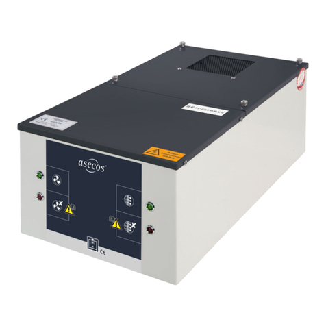
asecos UFA.20.30 user manual
Motor Guard
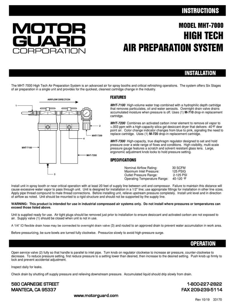
Motor Guard MHT-7000 instructions
purway Crystal Group
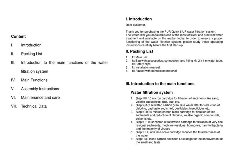
purway Crystal Group PUR Quick 6 UF installation manual
A.O. Smith
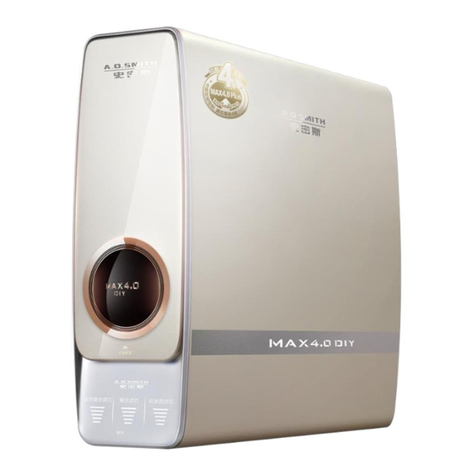
A.O. Smith aosbath MAX4 instruction manual
DeVilbiss
DeVilbiss HFRL-508 Service manual
