HIGHLY LIQUID MD24 User manual

Highly Liquid MD24 Hardware Revision G
Table of Contents
1.0 I portant Safety Infor ation...................................................................................................2
2.0 Feature Diagra ........................................................................................................................2
3.0 Mechanical Drawing.................................................................................................................3
4.0 Power Supply............................................................................................................................4
5.0 MIDI Wiring.............................................................................................................................5
6.0 Progra Switches.....................................................................................................................8
7.0 Re ote ACT/STBY LEDs........................................................................................................8
8.0 Outputs......................................................................................................................................9
8.1 Electrical Specifications.......................................................................................................9
8.2 Logic Wiring........................................................................................................................9
8.3 Servo Wiring......................................................................................................................10
1.0 Im ortant Safety Information
To prevent da age to the MD24 and connected devices, and to prevent personal injury:
●Take reasonable static-control precautions when handling the MD24. This product includes ESD-
sensitive parts.
●Use an appropriate power source.
●Do not exceed the electrical axi u ratings.
●Do not apply an external voltage to any of the MD24 outputs.
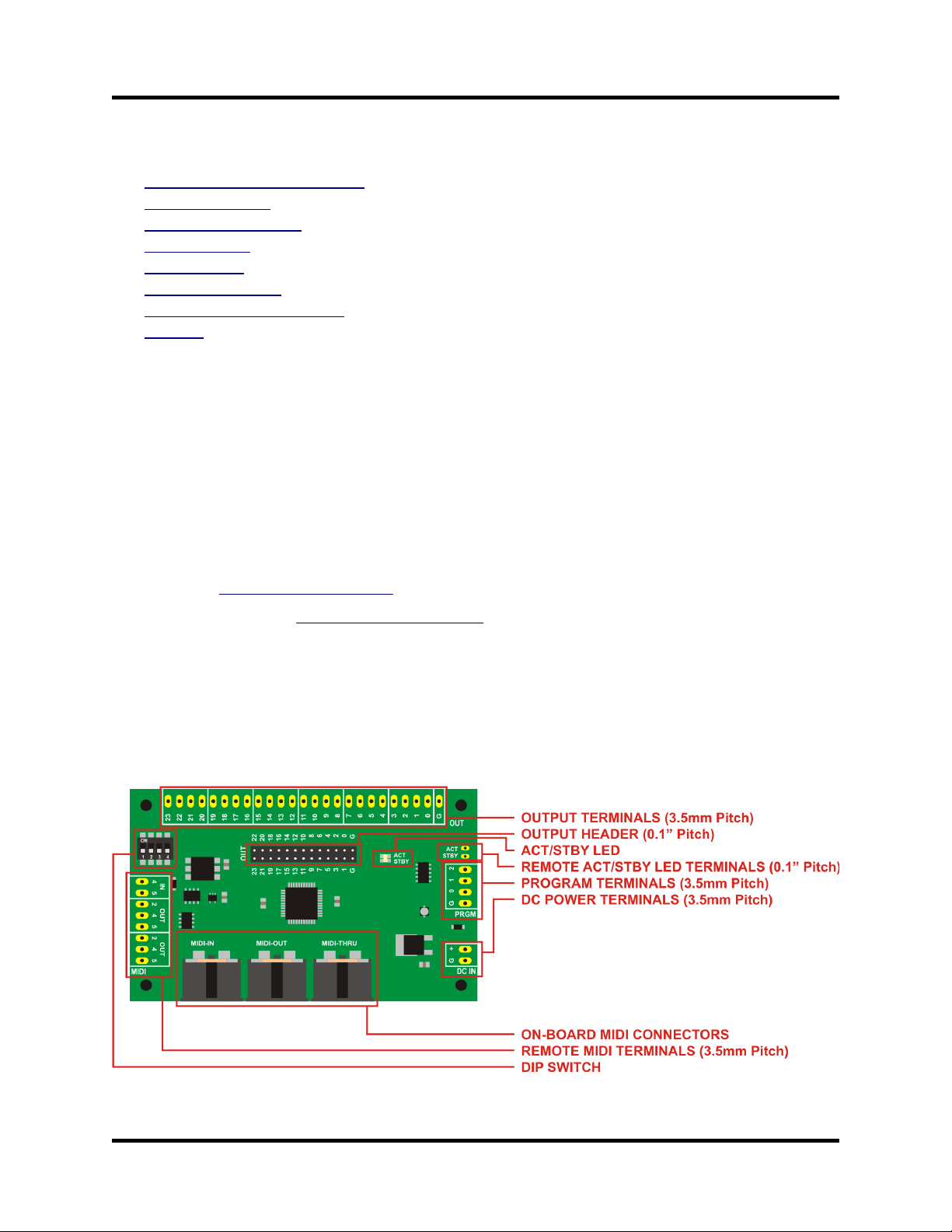
2.0 Feature Diagram
© 2011 Sonarcana LLC Page 2 / 10
Highly Liquid MD24 Hardware Revision G
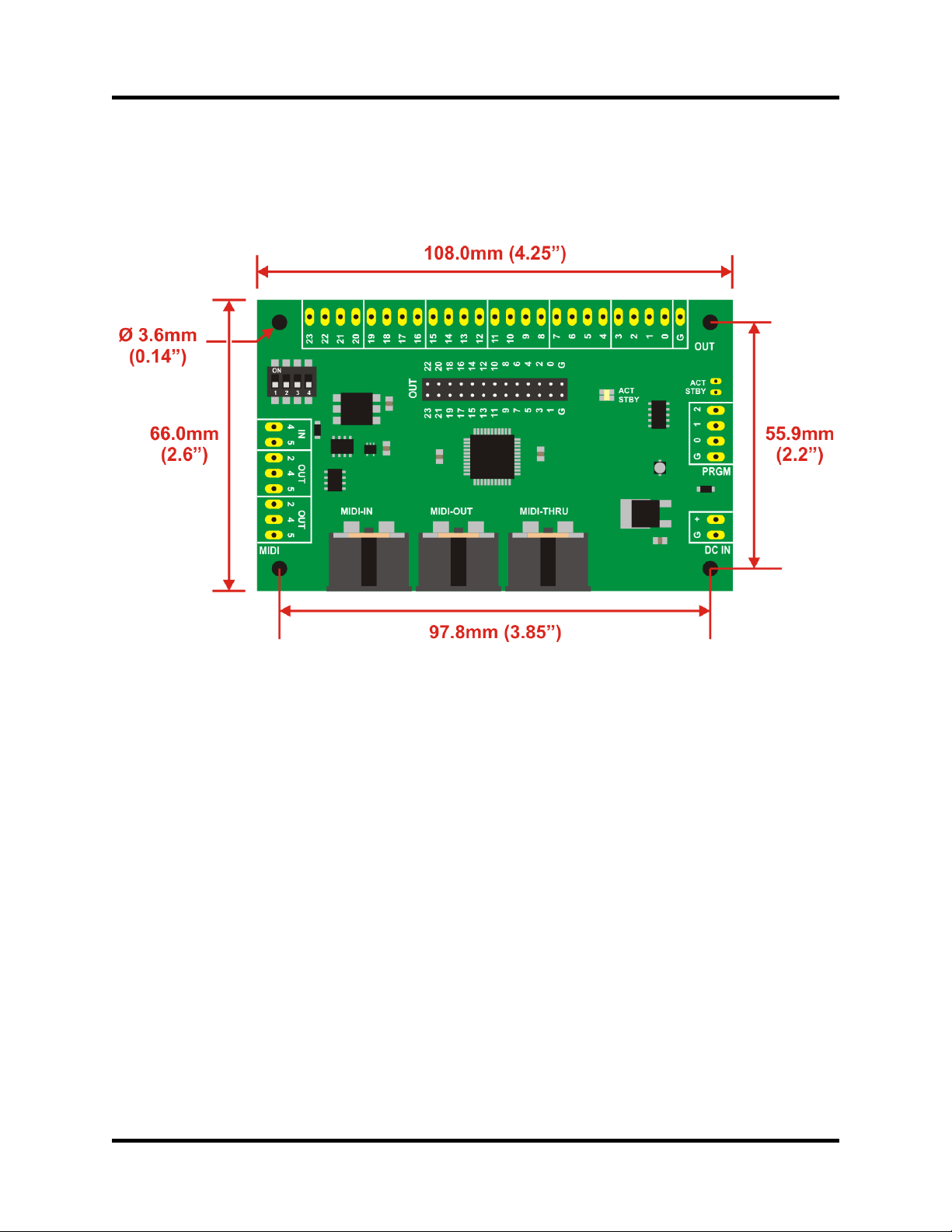
3.0 Mechanical Drawing
© 2011 Sonarcana LLC Page 3 / 10

Highly Liquid MD24 Hardware Revision G
4.0 Power Su ly
To operate, the MD24 ust be connected to a battery or other DC power supply. A “wall adapter” supply
with appropriate specifications ay be used.
Power supply require ents:
●Mini u output voltage: 6VDC
●Maxi u output voltage: 12VDC
●Current capacity: 300 A or greater
Wire the battery or power supply to the MD24 “DC IN” ter inals as shown in Figure 4.1.
Figure 4.1: Power Supply Wiring
© 2011 Sonarcana LLC Page 4 / 10

Highly Liquid MD24 Hardware Revision G
5.0 MIDI Wiring
The MD24 features MIDI IN, OUT and THRU ports.
Use the MIDI IN and MIDI THRU ports as shown in Figure 5.1. The MIDI THRU port sends an
unprocessed replica of the signal received at the MIDI IN port.
The MIDI OUT port can be used to retrieve the MD24 configuration via MIDI SysEx essage. See
MD24 Firmware User Manual.
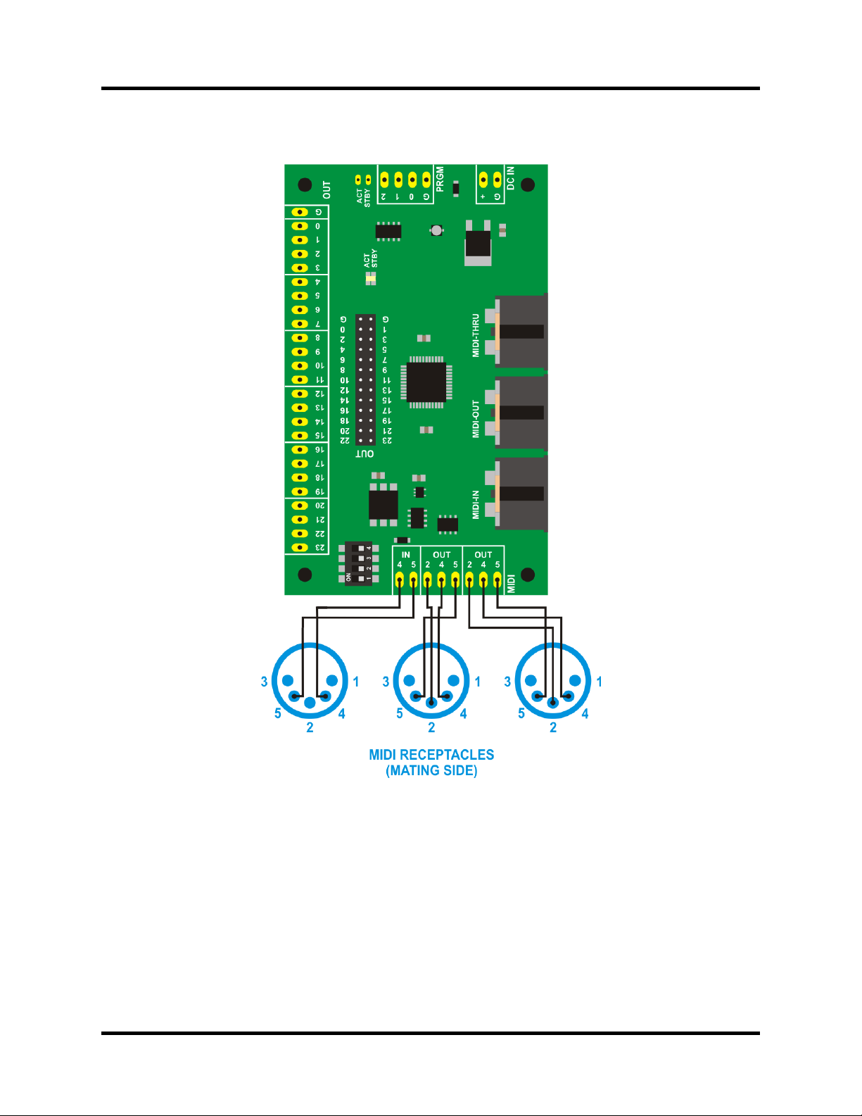
Re ote MIDI connectors can be used instead of the on-board MIDI connectors. Wire MIDI receptacles
as shown in Figure 5.2. Pin 2 is wired only at the OUT or THRU side of the MIDI link. Pins 1 & 3 are
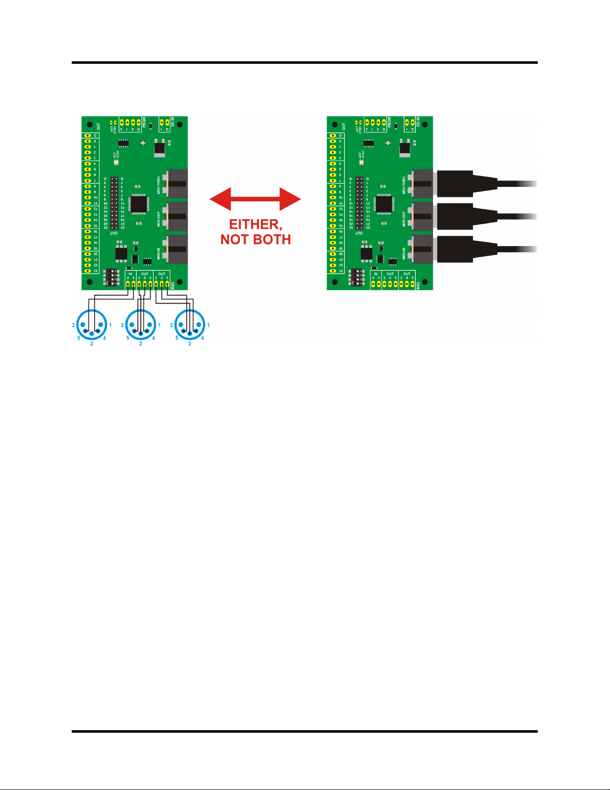
unused. Re ote MIDI connectors can not be used si ultaneously with the on-board MIDI connectors.
See Figure 5.3.
Figure 5.1: MIDI IN and MIDI HRU
© 2011 Sonarcana LLC Page 5 / 10
Highly Liquid MD24 Hardware Revision G
Figure 5.2: Remote MIDI Connector Wiring
© 2011 Sonarcana LLC Page 6 / 10
Highly Liquid MD24 Hardware Revision G
Figure 5.3: On-Board vs. Remote MIDI Connectors
© 2011 Sonarcana LLC Page 7 / 10
Highly Liquid MD24 Hardware Revision G
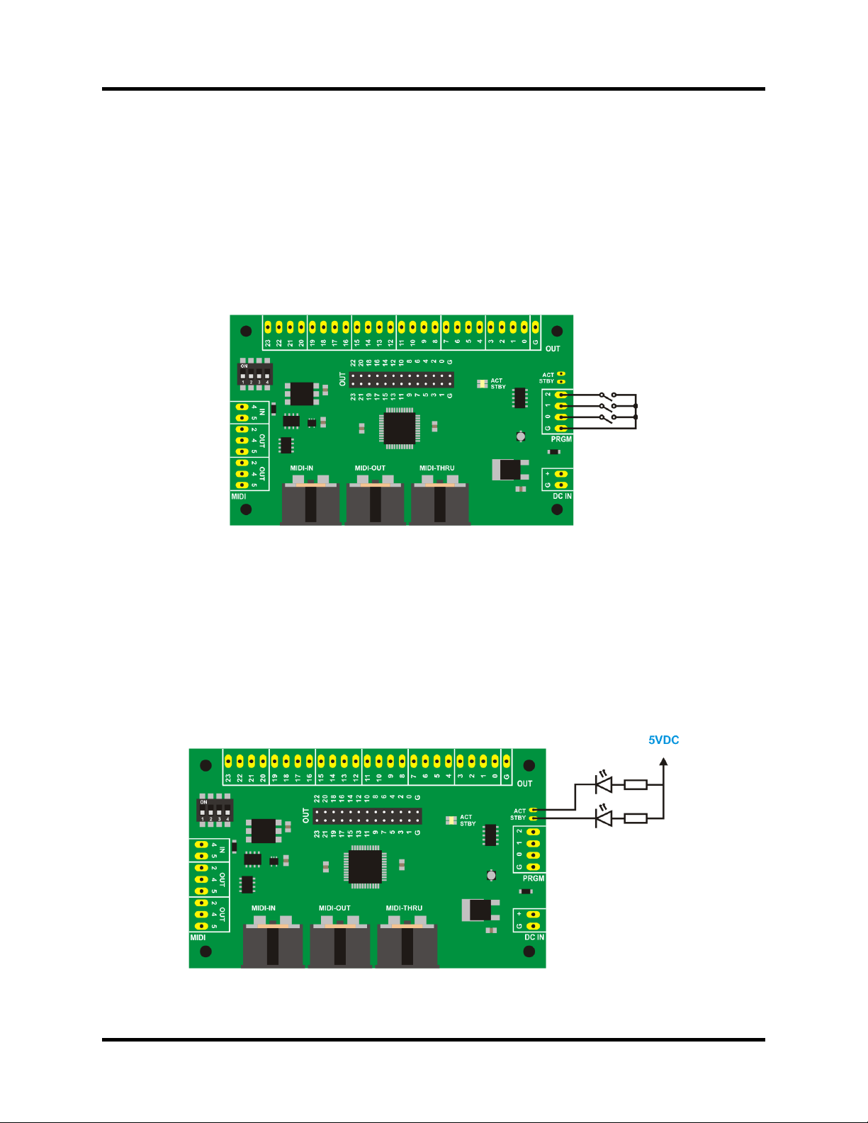
6.0 Program Switches
User-supplied “progra ” switches can be attached as shown in Figure 6.1.
If supported by fir ware, a progra switch can activate “learn ode” and other progra ing features of
the MD24. Use nor ally-open o entary switches. See MD24 Firmware User Manual for additional
details.
Figure 6.1: Program Switch Wiring
7.0 Remote ACT/STBY LEDs
The MD24 features on-board ACT/STBY LEDs. User-supplied re ote ACT/STBY LEDs can be
attached as shown in Figure 7.1. Li it the current thru each LED to 10 A.
Figure 7.1: Remote AC /S BY LED Wiring
© 2011 Sonarcana LLC Page 8 / 10

Highly Liquid MD24 Hardware Revision G
8.0 Out uts
8.1 Electrical S ecifications
●5V DC output, CMOS & TTL co patible
●Maxi u aggregate output current source/sink per MD24: 200 A
●Maxi u source/sink current per output: 25 A
8.2 Logic Wiring
Each MD24 output can be configured as a 5V “logic ode” output. See MD24 Firmware User Manual
for details. A logic ode output can be connected to CMOS or TTL logic inputs, can be used to power
LEDs, or can trigger other devices requiring a 5V signal.
Figure 8.1 shows a circuit which uses an LED to indicate the state of each MD24 logic ode output. The
value for current-li iting resistors will depend on choice of LED (1.0kΩ is typical).
Figure 8.1: LED Output Wiring
© 2011 Sonarcana LLC Page 9 / 10
Highly Liquid MD24 Hardware Revision G
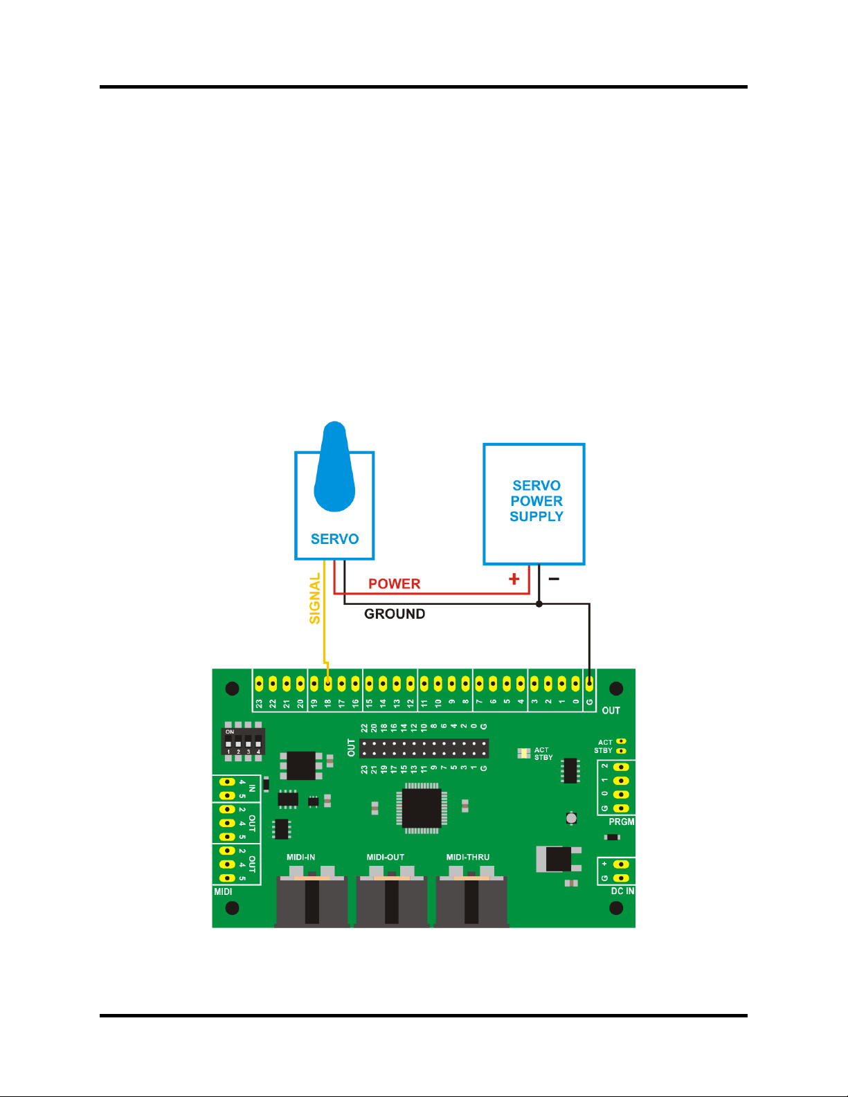
8.3 Servo Wiring
Each MD24 output can be configured as a “servo ode” output. A servo ode output generates a 5V
pulse width odulation (PWM) servo control signal. See MD24 Firmware User Manual for ore details.
A servo has three leads: ground, power input, and control input (“signal”). Each lead is identified by
color: ground is usually black, blue or brown; power input is usually red; and signal is usually white,
yellow, or orange. Exact colors vary by servo brand and odel.
MD24-to-servo wiring is shown in Figure 8.2. Output #18 is used as an exa ple, but the circuit can be
connected to any servo ode output. Repeat as needed for each servo/MD24 output pair.
The MD24 provides only the control signal. The power supply for the servo ust be provided separately.
See the docu entation provided by the servo anufacturer for power supply require ents. Most RC
servos will operate using a 5VDC or 6VDC power source.
Figure 8.2: Servo Output Wiring
© 2011 Sonarcana LLC Page 10 / 10
Table of contents


