Parker Compumotor RP240 User manual

-~
ARTISAN
®
~I
TECHNOLOGY
GROUP
Your definitive source
for
quality
pre-owned
equipment.
Artisan Technology
Group
Full-service,
independent
repair
center
with
experienced
engineers
and
technicians
on staff.
We
buy
your
excess,
underutilized,
and
idle
equipment
along
with
credit
for
buybacks
and
trade-ins
.
Custom
engineering
so
your
equipment
works
exactly as
you
specify.
•
Critical
and
expedited
services
•
Leasing
/
Rentals/
Demos
• In
stock/
Ready-to-ship
•
!TAR-certified
secure
asset
solutions
Expert
team
ITrust
guarantee
I
100%
satisfaction
All
tr
ademarks,
br
a
nd
names, a
nd
br
a
nd
s a
pp
earing here
in
are
th
e property of
th
e
ir
r
es
pecti
ve
ow
ner
s.
Find the Parker / Compumotor RP240 at our website: Click HERE

Table of Contents
i
TABLE OF CONTENTS
HowToUseThisUserGuide ....................................................................................................................i
Assumptions.................................................................................................................................i
User Guide Contents ......................................................................................................................i
Installation Process Overview................................................................................................................ii
Installation Procedures...................................................................................................................ii
Related Publications.............................................................................................................................ii
À
INTRODUCTION...............................................................................................................................1
ProductDescription..............................................................................................................................1
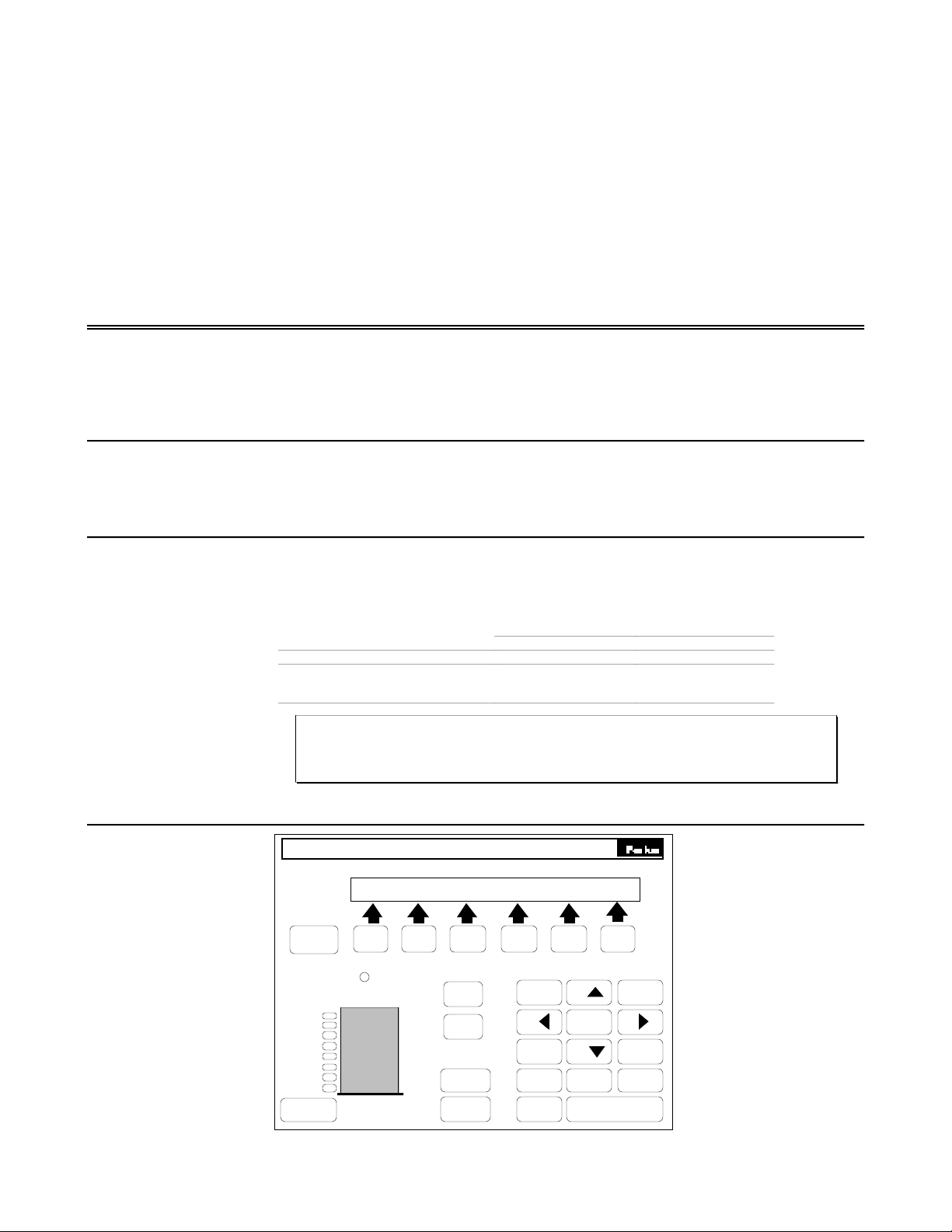
RP240 Features...................................................................................................................................1
`
GETTING STARTED.........................................................................................................................3
WhatYouShouldHave...........................................................................................................................3
Basic System Configuration...................................................................................................................3
Wiring Connections ........................................................................................................................4
´
INSTALLATION................................................................................................................................5
Environmental Considerations................................................................................................................5
Electrical Noise .............................................................................................................................5
Airborne Contaminants....................................................................................................................5
System Mounting.................................................................................................................................6
RP240 Door Mount .........................................................................................................................6
RP240 Dimensions.........................................................................................................................7
RP240-NEMA4 Door Mount ..............................................................................................................7
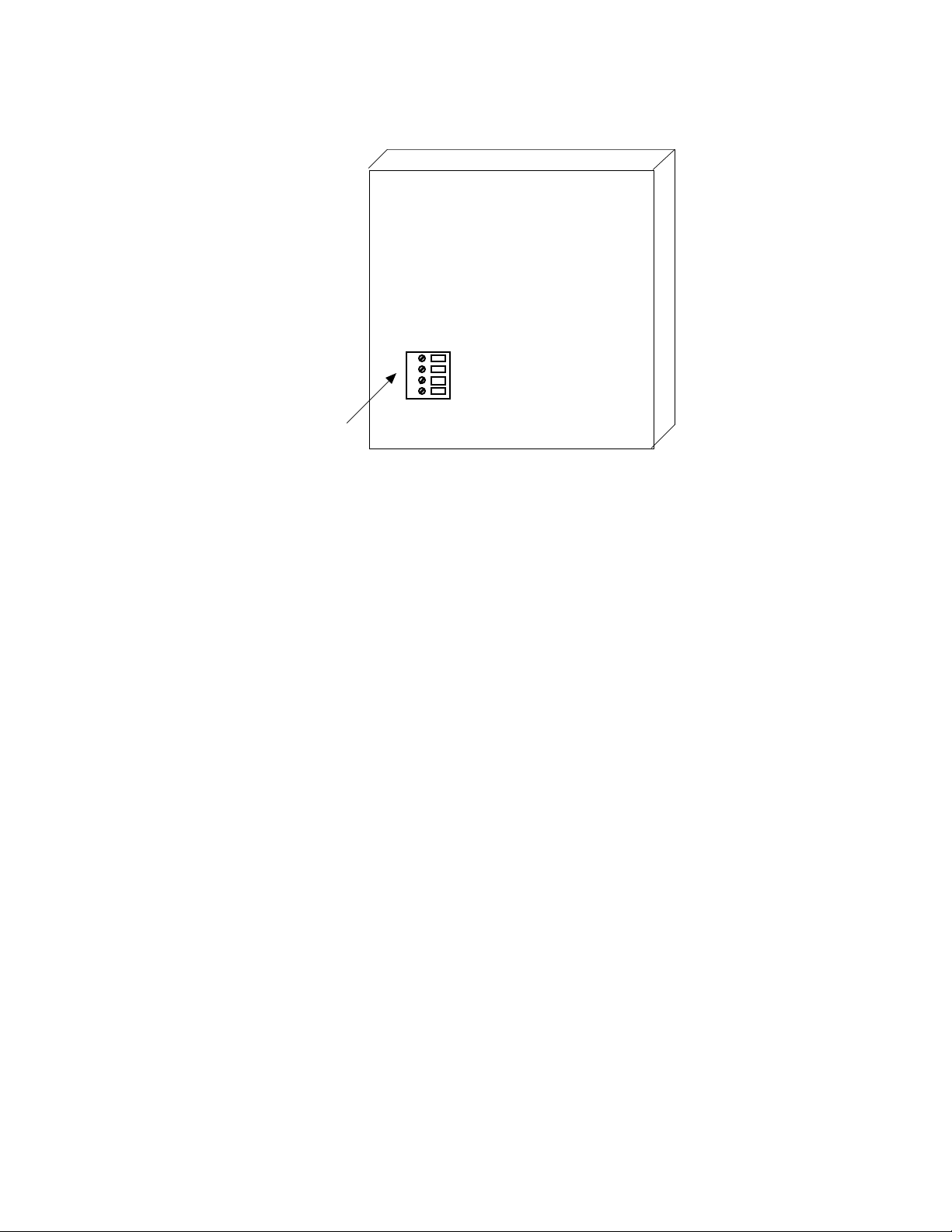
RP240Connections........................................................................................................................8
RP240toSXWiringDiagram..............................................................................................................9
RP240 to ZX Wiring Diagram.............................................................................................................9
RP240 to Model 500 Wiring Diagram...................................................................................................10
RP240 Connector Pin Out................................................................................................................10
Installation Verification.........................................................................................................................10
6000 Series ..................................................................................................................................10
Using the RP240 With An Extended X Language Product .......................................................................11
ˆ
EXTENDED X COMMAND SUMMARY AND APPLICATION DESIGN...........................................13
Extended X Language Command Summary ...............................................................................................13
Description of Extended X Language Command Format ...............................................................................14
Extended X Language Command Listing...................................................................................................15
Discussion of Extended X Language Commands........................................................................................20
Prompting an Operator or Displaying Information..................................................................................20
Extended X Language Command Programming Example........................................................................21
Processing Information...................................................................................................................23
Enabling STOP and PAUSE Keys......................................................................................................23
Sample Program ............................................................................................................................24
Editing Sequences.........................................................................................................................29
Daisy Chaining ..............................................................................................................................30
˜
6000 SERIES COMMAND SUMMARY AND APPLICATION DESIGN............................................33
6000 Series Command Summary.............................................................................................................33
Description 6000 Series Command Format ................................................................................................34
RP240 X Language Command Listing.......................................................................................................35
Prompting an Operator or Displaying Information..................................................................................38
6000 Series Command Programming Example......................................................................................39
Processing Information...................................................................................................................41
Enabling Jog Mode.........................................................................................................................41
ChangingthePassword ...................................................................................................................41
Artisan Scientific - Quality Instrumentation ... Guaranteed | (888) 88-SOURCE | www.artisan-scientific.com

ii
Table of Contents
¯
DIRECT RP240 CONTROL...............................................................................................................43
RP240 Overview..................................................................................................................................43
CommandSummary..............................................................................................................................43
RP240 Response—Extended X Mode ................................................................................................45
Key Press Response of RP240—6000 Mode .......................................................................................45
˘
HARDWARE REFERENCE.................................................................................................................47
Environmental.....................................................................................................................................47
Electrical Specifications........................................................................................................................47
RP240 Connector...........................................................................................................................47
Power..........................................................................................................................................47
RS-232C Communication.................................................................................................................47
˙
TROUBLESHOOTING.......................................................................................................................49
PROM Table........................................................................................................................................49
Troubleshooting...................................................................................................................................49
Reducing Electrical Noise................................................................................................................50
Diagnostic LEDs............................................................................................................................50
BasicTroubleshootingProcedure......................................................................................................50
Common Problems & Solutions .........................................................................................................51
RS-232C Communications ...............................................................................................................51
Editing Sequences—Extended X ......................................................................................................52
INDEX....................................................................................................................................................53
Artisan Scientific - Quality Instrumentation ... Guaranteed | (888) 88-SOURCE | www.artisan-scientific.com

Overview
iii
O V E R V I E W
How To Use This User Guide
This user guide is designed to help you install, develop, and maintain your
system. Each chapter begins with a list of specific objectives that should be
met after you have read the chapter. This section is intended to help you find
and use the information in this user guide.
Assumptions This user guide assumes that you have the skills or fundamental
understanding of the following information.
❏Basic electronics concepts (voltage, switches, current, etc.)
User Guide Contents
This user guide contains the following information.
Chapter ➀
Introduction This chapter provides a description of the product and a brief account of its
features.
Chapter ➁
Getting Started This chapter contains a detailed list of items you should have received with
your RP240 or RP240-NEMA4 shipment. It will help you become familiar
with the system and ensure that each component functions properly.
Chapter ➂
Installation This chapter provides instructions to properly mount the system and make
all electrical and non-electrical connections. Detailed instructions for
wiring the RP240 to Compumotor's 6200 Indexer and 6250 Servo Controller,
Model 500 Indexer, SX, and ZX Indexer/Drives is provided. Upon completion
of this chapter, your system should be completely installed and ready to
perform basic operations.
Chapter ➃
Extended X
Command Summary
and Application
Design
This chapter helps you integrate the RP240 to the Model 500 Indexer, and SX,
and ZX Indexer/Drives. Command enhancements to the X language
commands are described, and sample applications are provided.
Chapter ➄
6000 Series
Command Summary
& Application
Design
This chapter helps you integrate the RP240 to the 6200 Indexer, and 6250
Servo Controller. RP240 commands within the 6000 Series language are
described, and sample applications are provided.
Chapter ➅
Direct Control of
RP240
This chapter describes the internal command set of the RP240.
Chapter ➆
Hardware
Reference
This chapter contains information on system specifications (electrical, I/O,
etc.).
Artisan Scientific - Quality Instrumentation ... Guaranteed | (888) 88-SOURCE | www.artisan-scientific.com

iv
RP240 User Guide
Chapter ⑧
Troubleshooting This chapter describes Compumotor's recommended system maintenance
procedures. It also provides methods for isolating and resolving hardware
and software problems.
Installation Process Overview
To ensure safe, trouble-free system integration and operation, you should
pay special attention to the environment in which the RP240 equipment will
operate. Environmental conditions include the layout, mounting, and
wiring, grounding, and shielding practices used.
Installation Procedures
Before you install this product, you should complete the following steps:
➀Review this entire user guide. Become familiar with the user guide's contents
so that you can quickly find the information you need.
➁Read Chapter ➀Introduction to develop a basic understanding of all system
components, their functions, and interrelationships.
➂Read Chapter ➁Getting Started, and verify that you have received all the proper
components for your system, and that all the items in your shipment have
arrived without damage. Follow the step-by-step bench test procedures to
verify the basic functionality of the RP240.
➃After reading Chapter ➁begin the installation process. Do not deviate from the
sequence or installation methods provided.
➄Perform as many basic functions as you can with the configuration established
in Chapter ➁. You can perform this task only if you have reviewed the entire
user guide.
Related Publications
The following publications may be helpful resources.
❏Current Parker Compumotor Motion Control Catalog
❏User guide for the Compumotor Indexer or Servo Controller that you will use
with the RP240
❏Schram, Peter (editor). The National Electric Code Handbook (Third Edition).
Quincy, MA: National Fire Protection Association
Artisan Scientific - Quality Instrumentation ... Guaranteed | (888) 88-SOURCE | www.artisan-scientific.com

Chapter
➀
Installation
1
C H A P T E R ➀
Introduction
Chapter Objective
The information in this chapter will enable you to:
❏Understand the product's basic functions & features
Product Description
The RP240 is designed to operate as an operator interface for Compumotor's
Extended X (the SX Indexer/Drive, ZX Indexer/Drive, and Model 500 Indexer)
and 6000 Series products (6200 Indexer and 6250 Servo Controller). The
RP240 operates strictly as a dumb terminal. No programming of any kind
can be accomplished using the RP240. The RP240 is controlled by commands
available in the Extended X and 6000 Series command sets. The commands
allow the programmer to create a program (within the Extended X or 6000
Series product) to prompt an operator for numeric information, read
function keys, display variables and text, and control the 8 LEDs located on
the RP240.
If the RP240 is not used with the SX, ZX, Model 500, 6200, or 6250, ASCII
command strings sent directly to the RP240 can be used to control the
functions contained within the RP240 (refer to Chapter ➅Direct Control of
the RP240).
RP240 Features
❏Operates directly with Compumotor's SX and ZX Indexer/Drives, and the Model
500 Indexer
❏Operates directly with Compumotor's stand-alone 6000 Series products (6200
and 6250)
❏Can be used with any controller capable of transmitting ASCII strings across
RS-232C
❏Screw terminal connections for easy wiring
❏Optional NEMA specification ratings (standard RP240 is NEMA 12, optional
RP240-NEMA4 meets NEMA 4 & NEMA 12 specifications when panel mounted.)
❏Adjustable contrast for the LCD display
❏Eight independent LEDs
❏Numeric and function key data entry
❏Uses less than 100 mA of current at 5VDC
Artisan Scientific - Quality Instrumentation ... Guaranteed | (888) 88-SOURCE | www.artisan-scientific.com

Artisan Scientific - Quality Instrumentation ... Guaranteed | (888) 88-SOURCE | www.artisan-scientific.com

Chapter
➁
Getting Started
3
C H A P T E R ➁
Getting Started
Chapter Objectives
The information in this chapter will enable you to:
❏Verify that each component of your system has been delivered safely
❏Become familiar with system components and their interrelationships
What You Should Have
Inspect your RP240 shipment upon receipt for damage to its shipping
container. Report any damage to the shipping company as soon as possible.
Parker Compumotor cannot be held responsible for damage incurred in
shipment. The items listed in the table below should be present and in good
condition. RP240 RP240-NEMA4
Description Part # Part #
RP240 Main Unit RP-240 RP-240 NEMA4
Gasket 58-009135-01 58-013341-01
RP240 User Guide 88-012156-01 88-012156-01
CAUTION
Do not use sharp objects such as pencils, screw drivers, etc. on the front panel it will
cause permanent damage to the membrane and will void the warranty.
Basic System Configuration
F1 F2
MENU
RECA LL
1
23
4
5
6
7
89
0
.
+/-
C/E
ENTER
CONTRAST
INCREASE
CONTRAST
DECREASE
PAUSE
CONTINUE
STOP
POWER
F3 F4 F5 F6
1
2
3
4
5
6
7
8
RP240
Compumotor
Artisan Scientific - Quality Instrumentation ... Guaranteed | (888) 88-SOURCE | www.artisan-scientific.com

4
RP240 User Guide
Wiring Connections
The following figure illustrates the RS-232C and power; connector. This
connector is located on the back of the RP240.
☞Helpful Hint:
RP240 Back Panel
Gnd
Rx
Tx
+5 V
Back Panel
RS-232C
Connector
Artisan Scientific - Quality Instrumentation ... Guaranteed | (888) 88-SOURCE | www.artisan-scientific.com

Chapter
➂I
nstallation
5
C H A P T E R ➂
Installation
Chapter Objectives
The information in this chapter will enable you to:
❏Mount the RP240 properly
❏Wire the RP240 correctly
❏Verify that the complete system is installed properly
Environmental Considerations
☞Helpful Hint:
For more on NEMA
standards, contact the
National Electrical
Manufacturers
Association
, 2101 L
Street Northwest,
Washington, D.C.
20037. Ask for NEMA
Standards Publication
No. 250 Enclosures for
Electrical Equipment.
The RP240 is designed to be mounted to a door, on a panel front, desk, or
carried by hand. The RP240-NEMA4 is designed to be flush mounted in a
door. Both the RP240 and RP240-NEMA4 are designed to work in
temperatures up to 122°F (50°C). NEMA 12 specifications are achieved when
the RP240 is door or panel mounted using the provided gasket. NEMA 4
specifications are achieved when the RP240-NEMA4 is door or panel
mounted using the provided gasket. NEMA Type 12 enclosures provide a
degree of protection against dust, falling dirt, and dripping non corrosive
liquids. NEMA Type 4 enclosures provide a degree of protection against
windblown dust and rain, splashing water, and hose-directed water.
Electrical Noise Minimize the potential for electrical noise before installing the RP240
rather than attempting to solve such problems after installation. You can
prevent electrical noise by observing the following installation precautions:
❏Do not put high-voltage wires and low-level signals in the same conduit
❏Do not expose wiring (shield all wires)
❏Ensure that all components are properly grounded
Airborne Contaminants
Contaminants that may come in contact with the RP240 should be carefully
controlled. Particulate contaminants, especially electrically conductive
ones (such as metal shavings), can damage the RP240.
Artisan Scientific - Quality Instrumentation ... Guaranteed | (888) 88-SOURCE | www.artisan-scientific.com

6
RP240 User Guide
System Mounting
RP240 Door MountTo mount the RP240 operator panel to the door of an enclosure, or on a panel,
follow the steps below.
➀Drill four holes as shown in the following figure
➁Remove the bayonet mounts (screws and standoffs) and rubber feet from the
back of the operator panel (save the screws for mounting).
➂Put one screw through the door.
➃Put the gasket (provided) on the screw.
➄Put the operator panel onto the screw and tighten.
➅Align the panel and gasket and insert the remaining three screws.
➆Connect the 4 wires between the operator panel and the Extended X or 6000
Series product. See RP240 Connections later in this chapter.
6.90
0.90 6.90
0.60
1.95 0.83
Mounting Holes
0.187 Dia. (4 Plcs)
GND
Rx
Tx
+5V
Enclosure
Door Gasket
Artisan Scientific - Quality Instrumentation ... Guaranteed | (888) 88-SOURCE | www.artisan-scientific.com

Chapter
➂I
nstallation
7
RP240 Dimensions
The following figure shows the dimensional drawing for the RP240.
Mounting holes and their dimensions are given.
Compumotor RP240
1.50
8.70
8.10
6.90
0.90 6.90
0.60
1.95 0.83
0.76 0.60 Interface Connector
Location
Mounting holes
8-32 UNC (4 Plcs)
GND
Rx
Tx
+5V
RP240-NEMA4 Door Mount
To mount the RP240-NEMA4 operator panel through the door of an
enclosure, or in a panel, follow the steps below.
➀Cut an 8.3 inch vertical by 8.9 inch horizontal hole in the door of the enclosure
or panel as shown on the following page.
➁Drill eight holes in the locations shown.
➂Place the gasket (provided) on the RP240-NEMA4.
➃Put the operator panel through the door and tighten the eight nuts provided.
➄Connect the 4 wires between the operator panel and the Extended X (SX, ZX, or
Model 500) or the 6000 Series (6200 or 6250) product.
The following figure shows the dimensional drawing for the RP240-NEMA4.
Mounting studs and the required diameter clearance holes are given.
9.95
9.35
1.55
0.25
9.40
7.45
1.950.28
8.80
7.15
1.65
0.28
0.53
0.187 Diameter Clearence Holes
For #8-32 UNC-2B Studs (8x)
8.90 (Recommended Panel Cutout)
0.53 8.30 (Recommended Panel Cutout)
GND
Rx
Tx
+5V
RP240
Compumotor
Artisan Scientific - Quality Instrumentation ... Guaranteed | (888) 88-SOURCE | www.artisan-scientific.com

8
RP240 User Guide
Cutout in Cabinet Door
Gasket
RP240 Nema 4 Housing
Wiring Guidelines
☞Helpful Hint:
All earth ground
connections must be
continuous and
permanent.
Compumotor
recommends a single-
point grounding setup.
Proper grounding of electrical equipment is essential to ensure the safety of
personnel. You can reduce the effects of electrical noise due to
electromagnetic interference (EMI) by proper grounding. All Compumotor
equipment should be properly grounded. A good source of information on
grounding requirements is the National Electrical Code published by the
National Fire Protection Association of Boston, MA. In general, all
components and enclosures must be connected to earth ground through a
grounding electrode conductor to provide a low impedance path for ground
fault or noise-induced currents.
RP240 Connections
The RP240 operator panel is connected to the Extended X (SX, ZX, or Model
500) and 6000 Series (6200 or 6250) products by means of a four wire shielded
cable (user supplied). For cable lengths up to 50 feet long, Compumotor
recommends using 20 AWG wire. Cable lengths longer than 50 feet are not
recommended. This in accordance with the Electronic Industries
Association (EIA) recommendations for RS-232C at 9600 baud.
Artisan Scientific - Quality Instrumentation ... Guaranteed | (888) 88-SOURCE | www.artisan-scientific.com

Chapter
➂I
nstallation
9
To wire the RP240 to a 6000 Series product (6200 or 6250), connect the +5VDC
connection on the RP240 to the +5VDC source on the 6000 Series connector
labeled RP240. Connect the RP240 ground connection to the ground on the
6000 Series connector labeled RP240. Connect the RP240 Receive Data (Rx)
terminal to the controller's Transmit Data (Tx) terminal, and the RP240
Transmit Data (Tx) terminal to the controller's Receive Data (Rx) terminal.
Make all connections on the 6000 Series connector labeled RP240.
To wire the RP240 to an Extended X product, connect the +5VDC connection
on the RP240 to a +5VDC source capable of supplying 100 mA of current. You
must supply 5VDC ±2% to pin 1 of the RP240. You can use the 5VDC power
supplies on the SX, ZX, or Model 500 provided there is enough current
remaining. Current levels are shown in the table below.
Current Requirements
Available Encoder I/O RP240
SX 250 mA 150 mA 10 mA each 100 mA
ZX 500 mA 150 mA 0 mA 100 mA
500 500 mA 150 mA 0 mA 100 mA
Connect the RP240 ground connection to the ground of the +5VDC power
supply. Connect the RP240 Receive Data (Rx) to the controller's Transmit
Data (Tx), and the RP240 Transmit Data (Tx) to the controller's Receive Data
(Rx). Connect the RP240 only after you have programmed the controller for
operation with the RP240.
RP240 to SX Wiring Diagram
Rx
Tx
G
+5V
OPTO1
CW
CCW
HOME
OPTO2
REG
I1
AC Power
95-132VAC
50/60Hz
Compumotor
Gnd
Rx
Tx
+5 V
RP240 Rear Connector
RP240 to ZX Wiring Diagram
+5V
VOUT
ENBL
G
RX
TX
G
A+
A-
B+
B-
G
CW
CCW
HM
I1
I2
I3
I4
I5
I6
I7
O1
O2
O3
O4
G
SHLD
ENTER
I/O[1]
BRUSHLESS
SERVO DRIVE
SERIES
X
Gnd
Rx
Tx
+5 V
RP240 Rear Connector
Artisan Scientific - Quality Instrumentation ... Guaranteed | (888) 88-SOURCE | www.artisan-scientific.com

10
RP240 User Guide
RP240 to Model 500 Wiring Diagram
Model 500 Indexer
INC
ENCODER
ABS/INC
ENCODER
MOTOR
DRIVER
Rx
Tx
GND
EARTH
RS232
Gnd
Rx
Tx
+5 V
RP240 Rear Connector A +5VDC power source
is available at pin 23 of
either 25-pin D
connector.
Pin 23—+5VDC
Pin 14—Ground
RP240 Connector Pin Out
The following table provides the pin out for the RP240 connector.
Pin In/Out Function Description
1 In Ground Logic Ground
2 In Receive (Rx) RS-232C Receive Data input
3 Out Transmit (Tx) RS-232C Transmit Data output
4 In +5VDC Input Power (100 mA minimum)
Installation Verification
6000 Series To verify the operation of the RP240 and the 6000 Series product to which it
is connected, apply power to the 6000 Series product. The RP240 display
should look similar to one of the following screens. If you are using an
Extended X product, go to the next section.
S
O
A
OUMCP TOM
OURN JG
R 6 200 INDEXER
DI PL Y ETC
OOUMCP TOM
C UANCE
R 6 200 INDEXER
RSS
Artisan Scientific - Quality Instrumentation ... Guaranteed | (888) 88-SOURCE | www.artisan-scientific.com

Chapter
➂I
nstallation
11
Using the RP240 With An Extended X Language Product
☞Helpful Hint:
If you are using the
RP240 with a 6000
Series product, skip
this section.
Before continuing with this section, you should be familiar with the
Extended X Language product you will be using. An understanding of
programming sequences is important. Download the following program to
Sequence #100 in the Extended X Language product.
Command Description
>XE1ØØ Erase sequence #100
>XD1ØØ Begin definition of sequence #100
DCLRØ Clear all lines of the RP240 display
DPC1ØØ Cursor to line 1, column 0
DTXTTHIS_IS_A_QUICK_DEMO Display text at current cursor location
VAR1=FUN Wait for function key
DLED11111111 Turn on all LEDs
DCLRØ Clear all lines of RP240 display
DPC1ØØ Cursor to line 1, column 0
DTXTTHE_LEDS_WILL_TURN_OFF_IN_5_SECONDS Display text
T5 Wait 5 seconds
DLEDØØØØØØØØ Turn off all LEDs
DCLRØ Clear all lines of RP240 display
XT End sequence definition
>
Attach the RP240 after you have downloaded the above sequence correctly.
Cycle power. The following is displayed.
THIS SI A QUI CK DEMO
Press any function key to continue. After pressing any function key, all the
LEDs on the RP240 will turn on and the display will read as shown below.
THE DL T OFF I N SECOES URN 5 NDSWI LL
After 5 seconds, all the LEDs on the RP240 will turn off and the display will
be cleared.
Artisan Scientific - Quality Instrumentation ... Guaranteed | (888) 88-SOURCE | www.artisan-scientific.com

Chapter
➃
Extended X Command Summary and Application Design
13
C H A P T E R ➃
Extended X Command Summary and Application Design
Chapter Objectives
The information in this chapter will enable you to:
❏Program the SX, ZX, or Model 500 to control the RP240
❏Customize the system to meet your requirements
PROGRAMMING NOTE
This chapter provides Extended X programming information that is required to
communicate with the RP240. If you are using a 6000 Series product (6200 or 6250),
skip ahead to
Chapter
➄
6000 Series Command Summary and Application Design
.
Extended X Language Command Summary
Command Description
DCLR Clear the display
DCNT Enable/Disable PAUSE and CONTINUE Keys
DLED Turn RP240 LEDs On/Off
DPC Position Cursor
DSTP Enable/Disable STOP Key
DTXT Display Text Data on RP240 LCD
DVO Display Variable Data on RP240 LCD
VARn=FUN Enable and Read Function Keys
VARn=NUM Enable and Read Numeric Keypad
Artisan Scientific - Quality Instrumentation ... Guaranteed | (888) 88-SOURCE | www.artisan-scientific.com

14
RP240 User Guide
Description of Extended X Language Command Format
The following is a definition of the format fields for the Extended X Language
products.
➀DCLR Clear Display ➁Version
SX Rev C2
ZX Rev D
500 Rev C
➂Type
➃Syntax
➄Units
➅Range
➆Default
Programming
<DCLRn
line number
Ø, 1, 2
None
➇Attributes
[X]Buffered
[] Device specific
[] Saved independently
[] Saved in sequences
➈Response None
➉See Also DPC, DTXT, DVO
➀Mnemonic Code
and Full Name This box contains the command's mnemonic code.
➁Valid Revision
Level This field contains the revision history of the command. It includes the
revision of software when the command was added or modified. If the
revision level of software you are using is equal to or greater than the
revision level listed in this field, you are using the proper version of the
software.
➂Type This portion of the box contains the command type. All X Language RP240
commands are programming commands. All of these commands affect
program flow.
➃Syntax The proper syntax for the command is shown here. The specific parameters
associated with the command are also shown. Definitions of the parameters
are described below:
aThis indicates that a device address must accompany the command. Only the
device specified by this parameter receives and executes the command. If this
parameter, or any other parameter appears within brackets <a>, it is optional.
nThis represents an integer value.
bThis represents a binary value. The binary value must be either 0 or 1.
➄Units This field describes what unit of measurement or value the parameter in the
command syntax represents.
➅Range This is the range of valid values that you can specify for an argument (or any
other parameter specified).
➆Default The default setting for the command is shown in this box. A command will
perform its function with the default setting if you do not provide a value.
➇Attributes This field indicates that these commands are buffered. Buffered commands
are executed in the order that the system receives them with other buffered
commands. Buffered commands can be stored in a sequence.
➈Response There are no system responses associated with these X Language commands.
➉See Also Commands that are related or similar to the command described are listed
here.
Artisan Scientific - Quality Instrumentation ... Guaranteed | (888) 88-SOURCE | www.artisan-scientific.com

Chapter
➃
Extended X Command Summary and Application Design
15
Extended X Language Command Listing
DCLR Clear Display Version
SX Rev C2
ZX Rev D
500 Rev C
Type
Syntax
Units
Range
Default
Programming
<DCLRn
line number
0, 1, 2
None
Attributes
[X]Buffered
[] Device specific
[] Saved independently
[] Saved in sequences
Response None
See Also DPC, DTXT, DVO
The Clear Display (DCLR) command clears a specified line of the RP240 display, and repositions the cursor to
the beginning of the line.
n = Ø Clear all lines of the RP240 display
n = 1 Clear line 1 of the RP240 display
n = 2 Clear line 2 of the RP240 display
Command Description
> DCLR1 Clear line one (1) of the RP240 display
DCNT Enable/Disable Pause and Continue Version
SX Rev C2
ZX Rev D
500 Rev C
Type
Syntax
Units
Range
Default
Programming
<a>DCNTb
None
0, 1
0
Attributes
[X]Buffered
[] Device specific
[] Saved independently
[] Saved in sequences
Response None
See Also SSH, SSL
This command enables or disables the PAUSE and CONTINUE keys on the RP240.
o
DCNTØ Disable PAUSE and CONTINUE keys
o
DCNT1 Enable PAUSE and CONTINUE keys
When the PAUSE and CONTINUE keys are enabled (DCNT1), pressing the PAUSE key will cause the RP240 to send
a Stop (S) command to the Model 500, SX, or ZX. Pressing the CONTINUE key will cause a Continue (C)
command to be sent. To have the Model 500, SX, or ZX pause motion, the Save Command Buffer on Stop
(SSH1) and the Resume Execution Enable (SSL1) must be enabled.
Once you have activated the PAUSE and CONTINUE keys, they will remain active at all times, except when
numeric or function key information has been requested (VARn=NUM or VARn=FUN).
Command Description
>XE1ØØ Erase sequence #100
>XD1ØØ Begin definition of sequence #100
SSH1 Enable save command buffer on stop
SSL1 Enable resume execution
DCNT1 Enable PAUSE and CONTINUE keys
DSTP1 Enable STOP key
XT End definition of sequence #100
>
Artisan Scientific - Quality Instrumentation ... Guaranteed | (888) 88-SOURCE | www.artisan-scientific.com

16
RP240 User Guide
DLED Turn RP240 LEDs On/Off Version
SX Rev C2
ZX Rev D
500 Rev C
Type
Syntax
Units
Range
Default
Programming
<a>DLEDn
None
0, 1, X
0
Attributes
[X]Buffered
[] Device specific
[] Saved independently
[] Saved in sequences
Response None
See Also O
The DLEDcommand controls the state of the 8 LEDs on the RP240. A one will turn an LED on, a zero will turn
an LED off, and an X will leave the LED unchanged from its last state.
The command example below reads from left to right and corresponds to the LEDs from top to bottom.
Command Description
> DLED11ØØXX11 Turn LEDs 1,2,7, and 8 on, LEDs 3 and 4 off, and leave LEDs 5 and 6 unchanged
DPC Position Cursor Version
SX Rev C2
ZX Rev D
500 Rev C
Type
Syntax
Units
Range
Default
Programming
<a>DPCnxx
line number
1, 2
None
Attributes
[X]Buffered
[] Device specific
[] Saved independently
[] Saved in sequences
Response None
See Also DCLR, DTXT, DVO
The Position Cursor (DPC) command places the cursor at line n, column xx. The lines are numbered from top
to bottom, 1 to 2. The columns are numbered from left to right, 00 to 39.
You must use 00, 01, 02,...,09 instead of 0, 1, 2,..., 9 for the column number (i.e., DPC208, not DPC28).
00 01 02 03 04 05 06 07 08 09 10 11 12 13 14 15 16 17 18 19 20 21 22 23 24 25 26 27 28 29 30 31 32 33 34 35 36 37 38 39
Line 1
Line 2
Column
Once the cursor has been placed, all succeeding text (DTXT) or variable data (DVO) will be displayed
beginning at the current cursor location. All numeric data entered using the VARn=NUM command will also be
displayed at the current cursor location.
Command Description
>DPC2Ø5 Position the cursor on line 2, column 5
>DTXTCOMPUMOTOR_DEMO_PR
OGRAM Place message COMPUMOTOR DEMO PROGRAM at current cursor position
Artisan Scientific - Quality Instrumentation ... Guaranteed | (888) 88-SOURCE | www.artisan-scientific.com
Table of contents
Other Parker Recording Equipment manuals