HIK VISION 6 Inch Medium Speed Dome User manual

6 Inch Medium Speed Dome
User Manual
V2.0.0
2010-01

6 Inch Medium Speed Dome User Manual
1
Thank you for purchasing our product. If there is any question or request, please do not hesitate to contact dealer.
This manual is applicable to 6 Inch Medium Speed Dome.
This manual may contain several technically incorrect places or printing errors, and the content is subject to change without notice.
The updates will be added into the new version of this manual. We will readily improve or update the products or procedures described
in the manual.

6 Inch Medium Speed Dome User Manual
2
Safety Instruction
These instructions are intended to ensure that user can use the product correctly to avoid danger or property loss. The precaution
measure is divided into “Warnings” and “Cautions”:
Warnings: Neglecting any of the warnings may cause serious injury or death.
Cautions: Neglecting any of the cautions may cause injury or equipment damage.
Warnings Follow these safeguards to prevent serious
injury or death.
Cautions Follow these precautions to
prevent potential injury or material
damage.
Warnings
1. In the use of the product, you must be strict compliance with the electrical safety regulations of the nation and region.
2. Please use the power adapter, which is provided by normal company. The standard of the power adapter is AC24V/3A.
3. Do not connect several devices to one power adapter as adapter overload may cause over-heat or fire hazard.
4. Please make sure that the plug is firmly connected on the power socket.
5. When the product is installed on wall or ceiling, the device shall be firmly fixed.
6. If smoke, odors or noise rise from the device, turn off the power at once and unplug the power cable, and then please contact the
service center.
7. If the product does not work properly, please contact your dealer or the nearest service center. Never attempt to disassemble the
camera yourself. (We shall not assume any responsibility for problems caused by unauthorized repair or maintenance.)
Warnings
1. Do not drop the dome or subject it to physical shock, and do not expose it to high electromagnetism radiation. Avoid the equipment
installation on vibrations surface or places subject to shock (ignorance can cause equipment damage).
2. Do not place the dome in extremely hot, cold (the operating temperature shall be -30°C ~ +65°C), dusty or damp locations, or fire or
electrical shock will occur otherwise.
3. The dome cover for indoor use shall be kept from rain and moisture.
4. Exposing the equipment to direct sun light, low ventilation or heat source such as heater or radiator is forbidden (ignorance can
cause fire danger).
5. Do not aim the camera at the sun or extra bright places. A blooming or smear may occur otherwise (which is not a malfunction
however), and affecting the endurance of CCD at the same time.
6. Please use the provided glove when open up the dome cover, avoid direct contact with the dome cover, because the acidic sweat of
the fingers may erode the surface coating of the dome cover.
7. Please use a soft and dry cloth when clean inside and outside surfaces of the dome cover, not to use alkaline detergents.

6 Inch Medium Speed Dome User Manual
3
Table of Contents
Table of Contents......................................................................................................................................................... 3
Chapter 1 Brief Introduction........................................................................................................................................ 4
1.1 Description..................................................................................................................................................... 4
1.2 Outline ........................................................................................................................................................... 4
1.3 Functions ....................................................................................................................................................... 4
Chapter 2 Operation Instructions................................................................................................................................. 6
2.1 Power-up Action ............................................................................................................................................ 6
2.2 Basic Operations............................................................................................................................................ 6
2.3 Presets with Special Functions ...................................................................................................................... 7
Appendix 1 Lightning & Surge Protection................................................................................................................ 10
Appendix 2 RS485 Bus Connection ...........................................................................................................................11
Appendix 3 24VAC Wire Gauge & Transmission Distance ...................................................................................... 14
Appendix 4 Table of Wire Gauge Standards.............................................................................................................. 15

6 Inch Medium Speed Dome User Manual
4
Chapter 1 Brief Introduction
1.1 Description
Adopting the high-performance integral dome drive with auto iris, auto white balance and other capabilities, the medium speed dome
is integrated with the built-in pan/tilt unit and the digital receiver. The dome provides Manchester code and wiring failure diagnosis;
with precise drive, it features high reaction sensitivity and reliable running, ensuring superior image stability.
The medium speed dome can be widely applied to various monitoring scenes such as the river, forest, road, railway, airport, harbor, oil
field, sentry, plaza, park, scenic spot, street, station, stadium, etc.
1.2 Outline
Back Box
Dome Drive
Bubble
6 Inch Medium Speed Dome
1.3 Functions
zSelf-adaptive to Multiple Protocols
The dome is compatible with PELCO-D, PELCO-P and HIK-Code protocol, etc., and is capable of being self-adaptive to these
protocols without need of selecting protocol by DIP switch settings.
zKeyboard Control
The pan/tilt movement and zoom actions of dome can be controlled by the control keyboard, DVR, matrix, etc.
zLimit Stops
The dome can be programmed to move within the limit stops (left/right, up/down) which are configurable by the control keyboard,
DVR or client application software.
zPresets
Each of the user-definable presets can be programmed to use pan, tilt, camera settings and other settings. When preset is called, the
dome will automatically move to the defined position. User is allowed to add, modify, delete and call each preset.
z3D Intelligent Positioning
The speed dome can be controlled with the 2 buttons and scroll of mouse can be used under HIK-Code protocols with devices and

6 Inch Medium Speed Dome User Manual
5
client software. Click on a certain area and the device will move to the scene with corresponding point as the center. When a
rectangular area is selected by left-clicking the mouse, device will move to its center and enlarge it. With right-clicking, the lens will
zoom in, and the scroll can easily make the lens zooming, and mouse operation automatically incorporates zooming effect.
zAuto Focus
The auto focus enables the camera to focus automatically to maintain clear video images.
zIR Cut Filter
The IR cut filter can be set to Auto, Day and Night.In auto mode, the camera is capable of automatically switching Black & White
mode (Night) and Color mode (Day) with regard to environment lightening conditions. In manual switch mode, user can increase
sensitivity in low light conditions by switching to Black & White mode, while the Color mode is preferred in normal lighting
conditions.
zLow Light Electronic Shutter
The shutter speed will automatically slow down in low illumination conditions to maintain clear video images by extending the
exposure time. The feature can be enabled/disabled by the menu.
zWhite Balance (WB)
This feature automatically processes the viewed image to retain color balance over a color temperature range. The default setting for
auto white balance is ON.
zPatrol
The speed dome provides up to 3 patrols. In each patrol, user is allowed to specify the scanning track by a group of user-defined
presets, with the scanning speed between two presets and the dwell time at the preset separately programmable. Each patrol support 16
presets. Patrol 1 is presets1 to preset 16, patrol 2 is preset 17 to preset 32 , patrol 3 is preset 33 to preset 48.
zPattern
A pattern is a memorized, repeating series of pan, tilt, zoom, and preset functions that can be recalled with a command from a
controller or automatically by a configured function (park, time task, or power-up). By default the focus and iris are in auto status
during the preset is being memorized.
zPower-off Memory
This feature allows the dome to resume its previous position or status after power is restored. By default setting, the dome supports the
power-off memory capability with the dwell time of 3 minutes.

6 Inch Medium Speed Dome User Manual
6
Chapter 2 Operation Instructions
2.1 Power-up Action
After the power is applied, the speed dome will perform self-test action that begins with lens actions and then pan and tilt movement.
After completion of power-up self-test actions, the interface as shown in Figure 2.1 will be displayed on screen for 120 seconds.
The System Information displayed on the screen includes the Dome Address, Protocol, Version and other information. The
COMMUNICATION refers to the baud rate, parity,data bit and stop bit of the dome, e.g., “2400, N,8, 1” indicates the dome is
configured with the baud rate of 2400, no parity,8 data bits and 1 stop bit. Please refer to Section 3.3.1 for detailed information.
Figure 2.1
2.2 Basic Operations
The following operation shall be done with the use of control device or client software. The control devices include control keyboard
and DVR, etc. And the client refers to the client application software. Examples are given here for common operation provided that the
current control system supports following operation. Please refer to Client Software User Manual for detail operation guide.
Pan and tilt movement: Move the joystick to the desired direction, or press the Up/Down/Left/Right buttons.
Zoom operation: Press ZOOM+/TELE button to make the lens closer and magnify the scene. Press ZOOM-/WIDE button to make
the lens farther and minify the scene.
Focus operation: After FOCUS+/FAR button is pressed, the object far away will become clearer while the object in vicinity will be
ambiguous. After FOCUS-/NEAR button is pressed, the object in vicinity will become clearer while the object far away will become
ambiguous.
In auto focus mode, camera will focus automatically to maintain clear image. This feature can also be achieved by manually as well.
However, after other operation of device, camera will resume auto focus.
Iris operation: press IRIS+/OPEN to enlarge the iris and increase the image brightness. And by pressing IRIS-/CLOSE, the iris will
gradually shrink that decreases image brightness. In auto iris mode, the IRIS+/OPEN and IRIS-/CLOSE buttons are still operable.
However, after finishing other operation by dome, camera will resume auto iris action.
Preset operation:
Preset can be programmed or called through keyboard or menu. The dome provides 256 presets. Press the SHOT button and then the

6 Inch Medium Speed Dome User Manual
7
numeric keys to call the programmed preset. E.g., the callup of preset 08 can be achieved by pressing PRESET button and then the
numeral 08. Please refer to Section 3.3.4 for the configuration of presets.
Note: The callup of presets, including the presets with special functions, will be restricted by the limit stops if defined. Callup of
presets programmed out of the limit stops will be invalid.
2.3 Presets with Special Functions
The following presets are predefined with special functions:
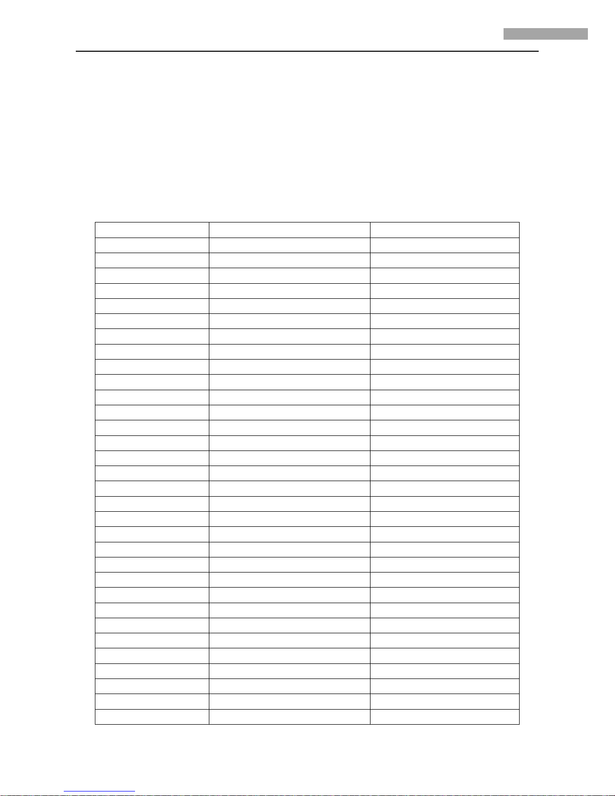
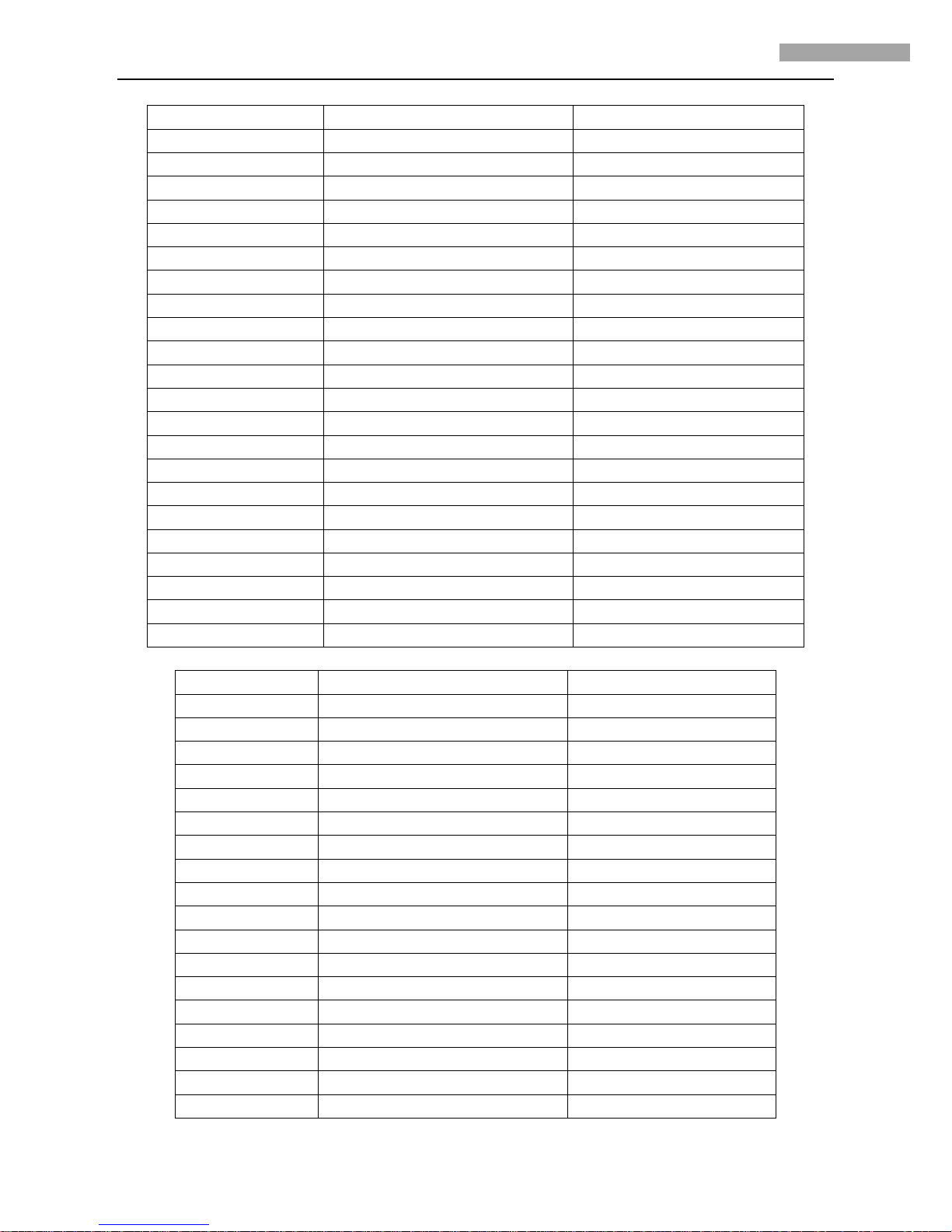
1. Using HIKVISION, PELCO-D, PELCO-P protocols, the preset and corresponding function are as below:
Presets Operation Call the preset Set the preset
1 to 50 Call functions Set functions
51(No.1 auto scan path) Start auto scan(high speed) Set auto scan starting position
52 Start auto scan(medium speed) Set auto scan end position
53 Start auto scan(low speed) ---
54 Reboot Restore to factory settings
55 Close camera auto restore Open camera auto restore
56(No.1 patrol) Start patrol (high speed) Set the patrol to stop for 10 seconds
57 Start patrol (medium speed) Set the patrol to stop for 30 seconds
58 Start patrol (low speed) Set the patrol to stop for 60 seconds
59 Start Sens Up(for SONY camera ) Close Sens Up(for SONY camera)
60 Auto focus Half-auto focus
61 Open park action Auto park action 10s
62 Close park action Auto park action 30s
63 Preset 1 Auto park action 60s
64 Preset 2 Auto park action 300s
65 Preset 3 Zoom Trigger focus
66 No.1 patrol Manual focus
67 No.1 Auto scan Open zoom display
68 No.1 Pattern (customized) Close zoom display
69 --- Night mode
70 --- Day mode
71 Start Pattern(customized) D/N auto switch
72 Pattern remember start(customized) Indoor
73 Pattern remember end(customized) Outdoor
74 Auto Trace White Balance Auto White Balance
75 Auto IRIS Manual IRIS
76 Open proportional pan/tilt Open BLC
77 Close proportional pan/tilt Close BLC
78 Open scan limit Open digital zoom
79 Close scan limit Close digital zoom
80(Auto scan path 2) Open speed level controlling Open camera power
81 Close speed level controlling Close camera power

6 Inch Medium Speed Dome User Manual
8
82 Open camera configuration Open parity and Verification
83(Auto scan path 3) Close camera configuration Close parity and Verification
84 --- Clear all presets information
85 --- ---
86(Auto scan path 4) --- ---
87 --- ---
88 --- ---
89(Auto scan path 5) --- ---
90 --- ---
91(No.2 auto scan) Start auto scan path (high speed) Set scan start position
92 Start auto scan path (medium speed) Set scan end position
93 Start auto scan path (low speed) ---
94 --- ---
95 --- ---
96(No.2 patrol) Start patrol(high speed) Set the patrol to stop for 10 seconds
97 Start patrol (medium speed) Set the patrol to stop for 30 seconds
98 Start patrol (low speed) Set the patrol to stop for 60 seconds
99(No.3 auto scan) Start auto scan path (high speed) Set scan start position
100 Start auto scan path (medium speed) Set scan end position
101 Start auto scan path (low speed) ---
102(No.3 patrol) Start auto scan path (high speed) Set the patrol to stop for 10 seconds
103 Start auto scan path (medium speed) Set the patrol to stop for 30 seconds
104 Start auto scan path (low speed) Set the patrol to stop for 60 seconds
2. Using Manchester code protocols(turn the 4th, 5th, 6th of SW2 on), the preset and corresponding function are as below:
Presets Operation Call the preset Set the preset
1 to 35 Call functions Set functions
36(No.1 auto scan path) Start auto scan(high speed) Set auto scan starting position
37 Start auto scan(medium speed) Set auto scan end position
38 Start auto scan(low speed) ---
39 Reboot Restore to factory settings
40 Close camera auto restore Open camera auto restore
41(No.1 patrol) Start patrol (high speed) Set the patrol to stop for 10 seconds
42 Start patrol (medium speed) Set the patrol to stop for 30 seconds
43 Start patrol (low speed) Set the patrol to stop for 60 seconds
44 Start Sensor Up(for SONY camera ) Close Sensor Up(for SONY camera)
45 Auto focus Half-auto focus
46 Open park action Auto park action 10s
47 Close park action Auto park action 30s
48 Preset 1 Auto park action 60s
49 Preset 2 Auto park action 300s
50 Preset 3 Zoom Trigger focus
51 No.1 patrol Manual focus
52 No.1 Auto scan Open zoom display

6 Inch Medium Speed Dome User Manual
9
53 No.1 Pattern (customized) Close zoom display
54 --- Night mode
55 --- Day mode
56 Start Pattern(customized) D/N auto switch
57 Pattern remember start(customized) Indoor
58 Pattern remember end(customized) Outdoor
59 Auto Trace White Balance Auto White Balance
60 Auto IRIS Manual IRIS
61 Open proportional pan/tilt Open BLC
62 Close proportional pan/tilt Close BLC
63 Open scan limit Open digital zoom
64 Close scan limit Close digital zoom
65 Open speed level controlling Open camera power
66 Close speed level controlling Close camera power
67 Open camera configuration Open parity and Verification
68 Close camera configuration Close parity and Verification
69 --- Clear all presets information
70 --- ---
Explanation:
Take using Pelco-P/D, HIKVISION protocols for example, integrated analog speed dome supports 3 patrols, each of which support 16
presets(patrol 1 supports preset 1 to present 16, patrol 2 supports preset 17 to present 32, patrol 3 supports preset 33 to present 48), the
stay time and speed can be set. The dome also support 2 auto scan path with movement limitation, the speed is adjustable. If don’t set
the movement limitation, it moves continuously. It support park action as well, and park action time is optional from 10s to 300s.
There are 6 modes can be chosen from (preset 1 to preset 3, auto scan 1 and patrol 1and pattern 1).
Detailed operation is described as below:
Call 56th preset to call patrol 1. Select the video in the DVR, press “PTZ” and “Rec”, and input 056 to start patrol 1, and the dome will
continuously scan among pre-set 16 presets. User can realize other function through the same meaning.

6 Inch Medium Speed Dome User Manual
10
Appendix 1 Lightning & Surge Protection
This product adopts TVS plate lightning protection technology to avoid damage caused by pulse signal that is below 3000W, like
instantaneous lighting, surging, etc. According to the actual situation outdoors, necessary protection measures must be taken to secure
the electrical safety.
1. The distance between signal transmission line and High-voltage equipment or high-voltage cable is at least 50m.
2. Outdoor wiring should better be along the eaves as much as possible.
3. In the open field, wiring should be buried underground in sealed steel pipe, and the steel-pipe should be one-point
grounding. Overhead routing method is forbidden.
4. In strong thunderstorm area or high induction voltage areas (such as high-voltage transformer substation), high power lightning
protection apparatus and lightning conductor are necessary to be appended.
5. The design for installation and wiring with lightning protection and grounding in mind should be combined with the lightning
protection consideration of the building, and conform to the related national standards and industry standards.
6. The system should be equipotentially grounded, and the grounding equipment must satisfy double-request of system anti-jamming
and electric safety, and it must not appear short circuit and open circuit with the zero conductor of strong grid. When the system is
grounding individual, the resistance should be no more than 4Ω, the section al area of the grounding cable should be no less than
25mm2. For grounding instructions, please refer to the Installation Manual of Speed Dome.

6 Inch Medium Speed Dome User Manual
11
Appendix 2 RS485 Bus Connection
1. General Property of RS485 Bus
According to RS485 industry bus standard, RS485 is a half-duplex communication bus which has 120Ωcharacteristic impendence, the
maximum load ability is 32 payloads (including controller device and controlled device).
2. RS485 Bus Transmission Distance
When using 0.56mm (24AWG) twisted-pair line, according to different baud rate, the max transmission distance theory table is shown
as below:
Baud Rate Max Distance
2400BPS 1800m
4800BPS 1200m
9600BPS 800m
The transmission distance will be decreased if we use the thinner cable, or use this product under the strong electromagnetic
interference situation, or there are lots of devices are added to the bus; on the contrary, the transmission distance will be increased.
3. Connection Method and Terminal Resistance
1) RS485 industry bus standard require daisy-chain connection method between any devices, both sides have to connect a 120Ω
terminal resistance (show as Diagram 1), the simplified connection method is shown as diagram 2, but the distance of “D”
should not be too long.
Diagram 1
Diagram 2
2) Connection of 120Ωterminal resistor
The 120Ωterminal resistor can be connected through the DIP switch on the communications board, as shown in Figure3. For a new
dome, the 120Ωmatching resistor is defaulted as unconnected, switch on the eighth bit of SW2, it will be connected. Conversely,
switch off the eighth bit of SW2, it will be unconnected.

6 Inch Medium Speed Dome User Manual
12
Figure 3
4. Problems in the PracticalApplication
Normally, users adopt star-shape connection method in construction, under this situation, the terminal resistors must be connected
between two farthest devices (as Figure 4, 1# and 15#), but this connection method is not satisfy the requirement of the RS485
industry standard so that it will lead to some problems such as signal reflection, anti-jamming ability decline when the devices are
faraway. At this time, the dome will be uncontrollable, or self-running, etc.
Figure 4
For such case, the best way is adding a RS485 distributor. This product can effectively change the star-shape connection to which
satisfies the requirement of RS485 industry standard, in order to avoid those problems and improve the communication reliability.
Show as figure 5.

6 Inch Medium Speed Dome User Manual
13
Figure 5
1. FAQ of RS485 Bus

6 Inch Medium Speed Dome User Manual
14
Appendix 3 24VAC Wire Gauge & Transmission Distance
The following table has described the recommended max. distance adopted for the certain wire gauge when the 24VAC voltage loss
rate is less than 10%. For the AC driven device, the maximum voltage loss rate allowable is 10%. For example, for a device with the
rating power of 80VA which is installed at a distance of 35 feet (10m) away from the transformer, then the minimum wire gauge
required is 0.8000mm.
WireGauge
mm
Distance
feet(m)
Power (va)

15
6 Inch Medium Speed Dome User Manual
Appendix 4 Table of Wire Gauge Standards
American Wire Gage
AWG (British)StandardWireGauge
SWG
Bare Wire Gauge
(mm) Cross-sectionalArea
of
mm
BareWire
2
Other manuals for 6 Inch Medium Speed Dome
1
Table of contents
Other HIK VISION Camera Accessories manuals

HIK VISION
HIK VISION DS-KABD8003-RS3 User manual

HIK VISION
HIK VISION 6 Inch Medium Speed Dome User manual

HIK VISION
HIK VISION DS-K3G411 Series User manual

HIK VISION
HIK VISION DS-K3G501 Series User manual

HIK VISION
HIK VISION DS-K3G501LX Series User manual

HIK VISION
HIK VISION DS-K3G200X Series User manual

HIK VISION
HIK VISION DS-2781 Series User manual

HIK VISION
HIK VISION UD04358B User manual