manuals.online logo
Brands
  1. Home
  2. •
  3. Brands
  4. •
  5. HIK VISION
  6. •
  7. Security Camera
  8. •
  9. HIK VISION DS-2CE71H0T-PIRL User manual

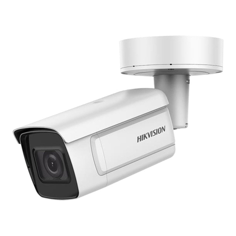
HIK VISION DS-2CE71H0T-PIRL User manual

UM D-2CE71H0T-PIRL 062118NA  2018 Hikvision USA Inc.
TurboHD
DS-2CE71H0T-PIRL
Bullet Camera
Use Manual
Thank you fo pu chasing ou p oduct. If the e a e any questions o equests, do
not hesitate to contact the deale .
This manual may contain seve al technical inco ect places o p inting e o s, and
the content is subject to change without notice. Updates will be added to new
ve sions of this manual. We will eadily imp ove o update the p oducts o
p ocedu es desc ibed in the manual.
UM D-2CE71H0T-PIRL 062118NA  2018 Hikvision USA Inc.
Regulatory Information
1
1 1 FCC Information
Please take attention that changes o modification not exp essly app oved by the
pa ty esponsible fo compliance could void the use ’s autho ity to ope ate the
equipment.
FCC Compliance: This equipment has been tested and found to comply with the
limits fo a Class A digital device, pu suant to pa t 15 of the FCC Rules. These limits
a e designed to p ovide easonable p otection against ha mful inte fe ence when
the equipment is ope ated in a comme cial envi onment. This equipment
gene ates, uses, and can adiate adio f equency ene gy and, if not installed and
used in acco dance with the inst uction manual, may cause ha mful inte fe ence to
adio communications. Ope ation of this equipment in a esidential a ea is likely to
cause ha mful inte fe ence in which case the use will be equi ed to co ect the
inte fe ence at his own expense.
1 2 FCC Conditions
This device complies with pa t 15 of the FCC Rules. Ope ation is subject to the
following two conditions:
1. This device may not cause ha mful inte fe ence.
2. This device must accept any inte fe ence eceived, including inte fe ence that
may cause undesi ed ope ation.
1 3 EU Conformity Statement
This p oduct and, if applicable, the supplied accesso ies too a e ma ked
with “CE” and comply the efo e with the applicable ha monized Eu opean
standa ds listed unde the Low Voltage Di ective 2014/35/EU, the EMC Di ective
2014/30/EU, the RoHS Di ective 2011/65/EU.
2012/19/EU (WEEE Di ective): P oducts ma ked with this symbol cannot
be disposed of as unso ted municipal waste in the Eu opean Union. Fo
p ope ecycling, etu n this p oduct to you local supplie upon the
pu chase of equivalent new equipment, o dispose of it at designated
collection points. Fo mo e info mation see: www. ecyclethis.info.
2006/66/EC (Batte y Di ective): This p oduct contains a batte y that
cannot be disposed of as unso ted municipal waste in the Eu opean
See the p oduct documentation fo specific batte y info mation. The
batte y is ma ked with this symbol, which may include lette ing to
indicate cadmium (Cd), lead (Pb), o me cu y (Hg). Fo p ope ecycling, etu n the
batte y to you supplie o to a designated collection point. Fo mo e info mation
see: www. ecyclethis.info.
1 4 Industry Canada ICES-003 Compliance
This device meets the CAN ICES-3 (A)/NMB-3(A) standa ds equi ements.
1 5 Warning
This is a class A p oduct. In a domestic envi onment this p oduct may cause adio
inte fe ence in which case the use may be equi ed to take adequate measu es.
1 6 Safety Instruction
These inst uctions a e intended to ensu e that use can use the p oduct co ectly to
avoid dange o p ope ty loss.
The p ecaution measu e is divided into “Wa nings” and “Cautions.”
Warnings: Se ious inju y o death may occu if any of the wa nings a e neglected.
Cautions: Inju y o equipment damage may occu if any of the cautions a e
neglected.
UM D-2CE71H0T-PIRL 062118NA  2018 Hikvision USA Inc.
Wa nings Follow
Cautions Follow these
these safegua ds to
p ecautions
to p event
p event se ious inju y
potential inju y o
o death.
mate ial damage.
1 7 Warnings
•In the use of the device, you must be in st ict compliance with the elect ical
safety egulations of the nation and egion.
•Input voltage should meet both the SELV (Safety Ext a Low Voltage) and the
Limited Powe Sou ce with 12 VDC acco ding to the IEC60950-1 standa d. Refe
to technical specifications fo detailed info mation.
•Do not connect multiple devices to one powe adapte to avoid ove heating o
a fi e haza d caused by ove load.
•Make su e that the plug is fi mly connected to the powe socket.
•Make su e that the device is fi mly fixed if wall mounting o ceiling mounting is
adopted.
•If smoke, odo , o noise ise f om the device, tu n off the powe at once and
unplug the powe co d, and then contact the se vice cente .
•Neve attempt to disassemble the came a by unp ofessional pe sonal.
1 8 Cautions
•Do not d op the came a o subject it to physical shock.
•Do not touch senso modules with finge s.
•Do not place the came a in ext emely hot, cold (the ope ating tempe atu e shall
be -40° to 60° C), dusty, o damp locations, and do not expose it to high
elect omagnetic adiation.
•If cleaning is necessa y, use a clean cloth with a bit of ethanol and wipe it
gently.
•Do not aim the came a at the sun o ext a b ight places.
•The senso may be bu ned out by a lase beam, so when any lase equipment is
in use, make su e that the su face of the senso will not be exposed to the lase
beam.
•Do not expose the device to high elect omagnetic adiation o ext emely hot,
cold, dusty, o damp envi onment.
•To avoid heat accumulation, good ventilation is equi ed fo the ope ating
envi onment.
•Keep the came a away f om liquid while in use fo non-wate p oof device.
•While in delive y, the came a shall be packed in its o iginal packing o packing of
the same textu e.
1 9 Mark Description
Table 0-1 Ma k Desc iption
Ma k Desc iption
DC Voltage
UM D-2CE71H0T-PIRL 062118NA  2018 Hikvision USA Inc.
Introduction
2
2 1 Product Features
The main featu es a e as follows:
High pe fo mance CMOS senso
IR cut filte with auto switch
OSD menu with configu able pa amete s
Auto white balance
Inte nal synch onization
SMART IR mode
Visible ala m
PIR detection
3-axis adjustment
2 2 Overview
Figu e 1, Came a Ove view
Installation
3
Before you start:
•Make su e that the device in the package is in good condition and all the
assembly pa ts a e included.
•Make su e that all the elated equipment is powe ed off du ing the
installation.
•Check the specification of the p oducts fo the installation envi onment.
•Check whethe the powe supply matches you equi ed output to avoid
damage.
•Make su e the wall is st ong enough to withstand th ee times the weight
of the came a and the mount.
•If the wall is cement, inse t expansion sc ews befo e installing the came a.
If the wall is wood, use self-tapping sc ew to secu e the came a.
•If the p oduct does not function p ope ly, contact you deale o the
nea est se vice cente . Do NOT disassemble the came a fo epai o
maintenance you self.
2 3 Ceiling/Wall Mounting without Junction Box
Steps:
1. Disassemble the came a.
1). Rotate the came a to align the notch to one of the ma ks.
UM D-2CE71H0T-PIRL 062118NA  2018 Hikvision USA Inc.
2). P y the mounting base to emove the mounting base f om the
came a body with a flat object (e.g., a coin).
2. Paste the d ill template (supplied) to whe e you want to install the
came a.
3. D ill the sc ew holes and the cable hole (optional) in the ceiling/wall
acco ding to the d ill template.
Figu e 2-1 D ill Template
Note:
D ill the cable hole when using the ceiling outlet to oute the cable.
4. Attach the mounting base to the ceiling/wall, and secu e them with
supplied sc ews.
Figu e 2, Attach the Mounting Base to the Ceiling
Note:
•
The supplied sc ew package contains self-tapping sc ews and expansion
bolts.
•
Fo cement wall/ceiling, expansion bolts a e equi ed to fix the came a.
Fo wood wall/ceiling, self-tapping sc ews a e equi ed.
5. Route the cables th ough the cable hole o the side opening.
6. Align the came a with the mounting base, and secu e the came a on
the mounting base.
UM D-2CE71H0T-PIRL 062118NA  2018 Hikvision USA Inc.
Figu e 3, Secu e the Came a to the Mounting Base
7. Connect the co esponding cables such as powe co d and video
cable.
8. Powe on the came a to check whethe the image on the monito is
at an optimum angle. If not, adjust the came a acco ding to the figu e
below to get an optimum angle.
Figu e 4, 3-axis Adjustment
1). Hold the came a body and otate the enclosu e to adjust the pan
position [0° to 360°].
2). Move the came a body up and down to adjust the tilt position
[0° to 75°].
3). Rotate the came a body to adjust the otation position [0° to
360°].
2 4 Mounting with Inclined Ceiling Mount
Before you start:
You need to pu chase an inclined ceiling mount sepa ately.
Steps:
1. Paste the d ill template (supplied) to whe e you want to install the
came a.
2. D ill sc ew holes and the cable hole on the ceiling/wall acco ding to
the supplied d ill template.
UM D-2CE71H0T-PIRL 062118NA  2018 Hikvision USA Inc.
Figu e 5, D ill Template
3. Disassemble the inclined ceiling mount with a sc ewd ive .
4. Install the tu et came a’s mounting base on the inclined ceiling
mount’s cove with th ee PM4 sc ews.
Figu e 6, Install Tu et Came a’s Mounting Base
5. Install the inclined ceiling mount’s body on the ceiling/wall with fou
PA4 × 25 sc ews, as shown.
UM D-2CE71H0T-PIRL 062118NA  2018 Hikvision USA Inc.
Figu e 7, Fix the Inclined Ceiling Mount’s Body
6. Fasten the inclined ceiling mount’s cove to its body with supplied
sc ews.
7. Repeat steps 5 to 8 of the 2.1 Ceiling/Wall Mounting without Junction
Box to complete the installation.
Figu e 8, Fix the Came a to the Inclined Ceiling Mount
2 5 Ceiling/Wall Mounting with Junction Box
Before you start:
You need to pu chase a junction box sepa ately.
Steps:
1. Paste the d ill template on the ceiling/wall.
UM D-2CE71H0T-PIRL 062118NA  2018 Hikvision USA Inc.
2. D ill sc ew holes and the cable hole (optional) in the ceiling/wall
acco ding to the holes of the d ill template.
Figu e 9, Junction Box D ill Template
Note:
D ill the cable hole, when using the ceiling outlet to oute the cable.
3. Take apa t the junction box, and align the sc ew holes of the tu et
came a’s mounting base with those on junction box’s cove .
4. Fix the mounting base on junction box’s cove by supplied sc ews.
Figu e 10, Install Tu et Came a’s Mounting Base
5. Secu e the junction box’s body with supplied sc ews on the
ceiling/wall.
UM D-2CE71H0T-PIRL 062118NA  2018 Hikvision USA Inc.
Figu e 11, Install the Junction Box’ Came a Body on Ceilling/Wall
6. Combine the junction box’s cove with the junction box’s body.
7. Repeat steps 5 to 8 of 2.1.1 Ceiling/Wall Mounting without Junction
Box to install the came a to the junction box.
Figu e 12, Fix the Came a to the Junction Box
UM D-2CE71H0T-PIRL 062118NA  2018 Hikvision USA Inc.
2 6 Wall Mounting
Before you start:
You need to pu chase a wall mount sepa ately.
Steps:
1. D ill fou sc ew holes in the wall acco ding to the holes of the mount.
2. Install the mount to the wall by aligning the fou sc ew holes of the
b acket with expansion sc ews on the wall.
3. Secu e the mount with fou hex nuts and washe s.
Figu e 13, Install the B acket
4. Install the mounting base of the tu et came a to the wall mount, and
secu e them with supplied sc ews.
Figu e 14, Install the Mounting Base to the B acket
5. Route the cables th ough the mount.
6. Repeat steps 6 to 8 of 2.1.1 Ceiling/Wall Mounting without Junction
Box to complete the installation.
UM D-2CE71H0T-PIRL 062118NA  2018 Hikvision USA Inc.
Menu Description
4
Purpose:
Call the menu by clicking button on the PTZ Cont ol inte face, o call the
p eset No.95.
Steps:
1. Connect the came a to the TVI DVR and the monito , shown as below.
Figu e 15, Connection
2. Powe on the analog came a, TVI DVR, and the monito to view the image
on the monito .
3. Click PTZ Cont ol to ente the PTZ Cont ol inte face.
4. Call the came a menu by clicking button, o call the p eset No. 95.
Figu e 16, Main Menu Ove view
UM D-2CE71H0T-PIRL 062118NA  2018 Hikvision USA Inc.
5. Click the di ection a ow to cont ol the came a.
1). Click Up/Down di ection button to select the item.
2). Click Iris+ to confi m the selection.
3). Click Left/Right di ection button to adjust the value of the selected
item.
2 7 VIDEO FORMAT
You can set the video fo mat to 5 MP @ 20 fps, 4 MP @ 25 fps, 4 MP @
30 fps, 2 MP @ 25 fps , o 2 MP @ 30 fps.
2 8 EXPOSURE
•EXPOSURE MODE
You can set the EXPOSURE MODE to GLOBAL, BLC, o DWDR.
•GLOBAL
GLOBAL efe s to the no mal exposu e mode, which adjusts lighting
dist ibution, va iations, and non-standa d p ocessing.
•BLC (Backlight Compensation)
BLC (Backlight Compensation) compensates light to the object in the
f ont to make it clea , but may cause ove exposu e of the
backg ound whe e the light is st ong.
•DWDR (Digital Wide Dynamic Range)
The digital wide dynamic ange helps the came a p ovide clea
images even unde backlight ci cumstances. WDR balances the
b ightness level of the whole image and p ovides clea images with
details.
•AGC (Auto Gain Control)
It optimizes the cla ity of the image in poo light conditions. The AGC
level can be set to HIGH, MEDIUM, o LOW. Select OFF to disable the
AGC function.
Note:
The noise will be amplified when the AGC is on.
2 9 DAY/NIGHT
COLOR, B&W (Black White), and AUTO a e selectable fo DAY and
NIGHT switches.
•COLOR
The image is in colo in day mode all the time.
•B/W
The image is black and white all the time, and it is bette to tu n the
IR LIGHT on in poo light conditions.
•IR LIGHT
You can tu n on/off the IR LIGHT to meet the equi ements of
diffe ent ci cumstances.
•SMART IR
The Sma t IR function adjusts the light to its most suitable intensity
and p events the image f om ove exposu e. The SMART IR value can
be adjusted f om 0 to 3. The g eate the value, the mo e obvious the
effect.
•AUTO
You can tu n on/off the IR LIGHT and set the SMART IR value in this
menu.
˗
IR LIGHT
You can tu n on/off the inf a ed to meet the equi ements of
diffe ent ci cumstances.
UM D-2CE71H0T-PIRL 062118NA  2018 Hikvision USA Inc.
Figu e 17, DAY NIGHT
>SMART IR
The Sma t IR function adjusts the light to its most suitable
intensity and p events the image f om ove exposu e. The
SMART IR value can be adjusted f om 0 to 3. The highe
the value, the mo e obvious the effects.
•D-N THRESHOLD (Day to Night Threshold)
Day to Night Th eshold cont ols the sensitivity of switching the day
mode to night mode. You can set the value f om 1 to 9. The la ge the
value, the mo e sensitive the came a.
•N-D THRESHOLD (Night to Day Threshold)
Night to Day Th eshold cont ols the sensitivity of switching the night
mode to day mode. You can set the value f om 1 to 9. The la ge the
value, the mo e sensitive the came a.
2 10 VIDEO SETTINGS
Move the cu so to VIDEO SETTINGS and click Iris+ to ente the
submenu. CONTRAST, SHARPNESS, COLOR GAIN, 3 DNR, and MIRROR
a e adjustable.
Figu e 18, VIDEO SETTING
UM D-2CE71H0T-PIRL 062118NA  2018 Hikvision USA Inc.
•WHITE BALANCE
White balance, the white endition function of the came a, adjusts
the colo tempe atu e acco ding to the envi onment. It can emove
un ealistic colo casts in the image. You can set WHITE BALANCE
mode to AUTO o MANUAL.
•AUTO
Unde AUTO mode, white balance is being adjusted automatically
acco ding to the colo tempe atu e of the scene illumination.
•MANUAL
You can set the R-GAIN/B-GAIN value f om 1 to 255 to adjust the
image’s shades of ed/blue.
Figu e 19, MWB MODE
•BRIGHTNESS
B ightness efe s to the b ightness of the image. You can set the
b ightness value f om 1 to 9 to da ken o b ighten the image. The
g eate the value, the b ighte the image.
•CONTRAST
This featu e enhances the diffe ence in colo and light between pa ts
of an image. You can set the CONTRAST value f om 1 to 9.
•SHARPNESS
Sha pness dete mines the amount of detail an imaging system can
ep oduce. You can set the SHARPNESS value f om 1 to 9.
•SATURATION
Adjust this featu e to change the satu ation of the colo . The value
anges f om 1 to 9.
•DNR (Digital Noise Reduction)
The DNR function can dec ease the noise effect, especially when
captu ing moving images in poo light conditions, and delive mo e
accu ate and sha pe images. You can set the DNR value f om 1 to 9.
•MIRROR
OFF, H, V, and HV a e selectable fo mi o .
OFF: The mi o function is disabled.
H: The image flips 180° ho izontally.
V: The image flips 180° ve tically.
HV: The image flips 180° both ho izontally and ve tically.
2 11 FUNCTIONS
•WHITE LIGHT
The embedded white light sou ce can be wo ked as the visible ala m.
In the WHITE LIGHT mode, you can set the mode to ALARM o OFF.
When you select the WHITE LIGHT as ALARM, you can set the
Pa amete s in the TRIGGER MODE and the ALARM MODE to meet
you needs.
UM D-2CE71H0T-PIRL 062118NA  2018 Hikvision USA Inc.
˗
TRIGGER MODE
>DVR
Set the TRIGGER MODE to DVR. In this way, the ala m
signal is sent f om the DVR and the came a wo ks as the
ala m detecto in the p ocess. Besides, the ala m type only
suppo ted by the DVR can also t igge the visible ala m in
the came a.
>CAMERA
Set the TRIGGER MODE to CAMERA, the embedded PIR
module sends the ala m signal to the visible ala m in the
came a, when the PIR module detects the ala m sou ce.
˗
ALARM
You can set the ALARM MODE to SOLID o FLASHING.
Figu e 20, ALARM MODE
Set the ALARM MODE to SOLID. In this way, the white light
sou ce tu ns on when the PIR module eceives the ala m
signal.
In the TIME SETTING you can set the time as 5s, 10s, 15s, 30s,
o 60s, which means that the solid mode stays fo the set time
when the came a eceives one ala m signal.
Note:
The solid mode will stay fo anothe set time when the second ala m
signal is eceived, and the est can be done in the same way.
>FLASHING
Set the ALARM MODE to FLASHING. In this way, the white
light sou ce flashes when the PIR module eceives the
ala m signal.
>OFF
Select OFF to disable this function.
•PIR LEVEL
Adjust the sensitivity of the PIR module. The highe the value, the
mo e sensitive the PIR module.
•FACTORY DEFAULT
Reset all the settings to the facto y defaults.
•EXIT
Move the cu so to EXIT and click Iris+ to exit the menu.
•SAVE & EXIT
Move the cu so to SAVE & EXIT and click Iris+ to save the settings,
and exit the menu.

Other HIK VISION Security Camera manuals

HIK VISION DS-2CE12DFT-PIRXOF28 User manual

HIK VISION

HIK VISION DS-2CE12DFT-PIRXOF28 User manual

HIK VISION TURBO HD D0T PIR Series User manual

HIK VISION

HIK VISION TURBO HD D0T PIR Series User manual

HIK VISION DS-2XE62 2F-IS Series User manual

HIK VISION

HIK VISION DS-2XE62 2F-IS Series User manual

HIK VISION DS-2DE1A400IW-DE3 User manual

HIK VISION

HIK VISION DS-2DE1A400IW-DE3 User manual

HIK VISION HWT-B123-M User manual

HIK VISION

HIK VISION HWT-B123-M User manual

HIK VISION DS-2CC502P-DG1 User manual

HIK VISION

HIK VISION DS-2CC502P-DG1 User manual

HIK VISION DS-2CE56D0T-IRMMF User manual

HIK VISION

HIK VISION DS-2CE56D0T-IRMMF User manual

HIK VISION HiWatch HWI-D620H-Z User manual

HIK VISION

HIK VISION HiWatch HWI-D620H-Z User manual

HIK VISION DS-2CD2142FWD-IWS User manual

HIK VISION

HIK VISION DS-2CD2142FWD-IWS User manual

HIK VISION DS-2DF5274-A User manual

HIK VISION

HIK VISION DS-2DF5274-A User manual

HIK VISION DS-2TD95C8-190ZK2FL/W User manual

HIK VISION

HIK VISION DS-2TD95C8-190ZK2FL/W User manual

HIK VISION DS-2AE5223TI-A User manual

HIK VISION

HIK VISION DS-2AE5223TI-A User manual

HIK VISION DS-2CC51A7N-VP User manual

HIK VISION

HIK VISION DS-2CC51A7N-VP User manual

HIK VISION DS-2AF1-611X User manual

HIK VISION

HIK VISION DS-2AF1-611X User manual

HIK VISION DS-2DF8223I-AEL User manual

HIK VISION

HIK VISION DS-2DF8223I-AEL User manual

HIK VISION DS-2CE11H0T-PIRLP User manual

HIK VISION

HIK VISION DS-2CE11H0T-PIRLP User manual

HIK VISION iDS-TCV907 User manual

HIK VISION

HIK VISION iDS-TCV907 User manual

HIK VISION DS-2CD2086G2-IU User manual

HIK VISION

HIK VISION DS-2CD2086G2-IU User manual

HIK VISION IPC-B220-IZ User manual

HIK VISION

HIK VISION IPC-B220-IZ User manual

HIK VISION DS?2CD753F?E User manual

HIK VISION

HIK VISION DS?2CD753F?E User manual

HIK VISION Network Mini Dome Camera User manual

HIK VISION

HIK VISION Network Mini Dome Camera User manual

HIK VISION DS-2XM6756FWD-IS User manual

HIK VISION

HIK VISION DS-2XM6756FWD-IS User manual

HIK VISION DS-2XC6245G0-L User manual

HIK VISION

HIK VISION DS-2XC6245G0-L User manual

HIK VISION UD04363B User manual

HIK VISION

HIK VISION UD04363B User manual

Popular Security Camera manuals by other brands

Novus NVDN-861H/IRH-2 user manual

Novus

Novus NVDN-861H/IRH-2 user manual

Sony SNC-HMX70 Application guide

Sony

Sony SNC-HMX70 Application guide

Vivotek FD8372 Quick installation guide

Vivotek

Vivotek FD8372 Quick installation guide

Uniden App Cam Solo PT quick start guide

Uniden

Uniden App Cam Solo PT quick start guide

Panasonic WV-CZ352 Specifications

Panasonic

Panasonic WV-CZ352 Specifications

Riva RC3500 Quick installation guide

Riva

Riva RC3500 Quick installation guide

Speco CVC-614C instruction manual

Speco

Speco CVC-614C instruction manual

Hanwha Techwin WISENET XNV-6080RSA quick guide

Hanwha Techwin

Hanwha Techwin WISENET XNV-6080RSA quick guide

FLIR DBV534TL quick start guide

FLIR

FLIR DBV534TL quick start guide

Starlight Xpress SXV-M25C user manual

Starlight Xpress

Starlight Xpress SXV-M25C user manual

D-Link DCS-8000LHV2 user manual

D-Link

D-Link DCS-8000LHV2 user manual

DynaColor W series user manual

DynaColor

DynaColor W series user manual

Novus NVIP-3SD-6200/20 user manual

Novus

Novus NVIP-3SD-6200/20 user manual

Moog FDW7CN-3 SERIES Specifications

Moog

Moog FDW7CN-3 SERIES Specifications

TRENDnet TV-IP343PI user guide

TRENDnet

TRENDnet TV-IP343PI user guide

Abus TVHD40000 user manual

Abus

Abus TVHD40000 user manual

Abus TVAC15010C user guide

Abus

Abus TVAC15010C user guide

3S Vision N9012 Hardware installation

3S Vision

3S Vision N9012 Hardware installation

manuals.online logo
manuals.online logoBrands
  • About & Mission
  • Contact us
  • Privacy Policy
  • Terms and Conditions

Copyright 2025 Manuals.Online. All Rights Reserved.