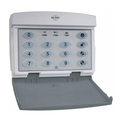
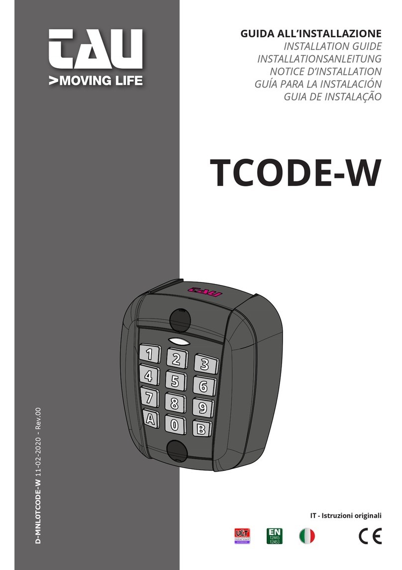
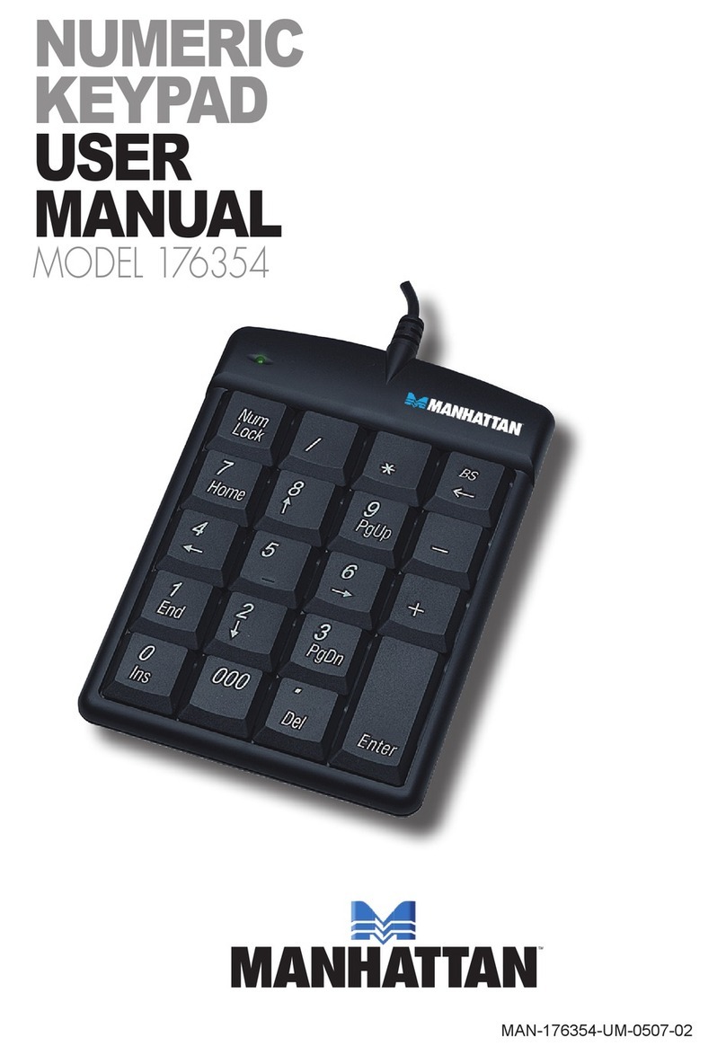
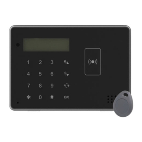
Hiland K5000 User manual

A6 version
Wireless keypad K50XX User Manual
I. Safety Instruction
1. It is only allowed to be installed by professional.
2. Ensure that the numerical value needed is the same as the specification before installing.
3. It is only used for automatic gate and other similar mechanical devices.
II. Product Instruction
1. It is a 2-channel Transmitter (433.92MHz) and only can be activated by pressing correct password.
2. It can be installed both inside and outside room.
3. The product can ensure the maximum safety because of the changing code for each time.
4. Working range can reach 100 meters in the open area outdoor. Indoor range is 35m.
5. Use CR2450 battery; working voltage is 3V; loading capacity is 580mAH.Weight 239g.
6. The design extends the battery life. It can work for 2 years with 10 operations per day.
7. Instruction of Led light and key button:
NO NAME MEANS
Led definitions
(from left to right)
1 A Button 1 one transmitter A
2 1 Press response
3 2 Battery voltage low, or enter your new password
again when you modify the password
4 B Button 2 on transmitter B
Key definitions 0~9 Number keys Password
A、B Letter keys A: Button 1 on transmitter A.
B: Button 2 on transmitter B.
Size:93*73*43mm
Indicator Light: “A, 1, 2, B”
www.stedaparts.nl

A6 version
III. Operation Instruction
Keypad needs a password, for example,
Enter 0~9 in any combination of numbers on the keypad, press confirm button, press button A or button B
according to the actual situation. Press button A to select receiver channel 1, press the button B
to select receiver channel 2.
It is only sending out signal when you press the correct password, if you enter the incorrect password then no
response. It is only recorded the last entered 6 bit password, for example, if the correct password is "123456",
then "*123456" is the right password ( ‘’ *’’ representative any number); but "123456#" is wrong password.
If press wrong password, there is no response for either button A or button B, you should to press the correct
password again.
It should be less than 4 seconds when pressing each password number, otherwise you need to press again.
Factory set up password for channel 1 and 2 are 000000
IV. Password Modification
Channel 1 password modification: Keep press button A. Eg:
Step Press button LED
1、Keep pressing button A longer than 2 seconds
Button A(keep pressing)“A”light up
2、Write the old password and press button A
000000 button A “A+1” light up
3、Write the new password and press button A
654321 button A “A+1+2” light up
4、
Write the new password again and press button A
654321 button A “A+1+2”Flash together twice and then off
Channel 2 password modification: Keep press button B. Eg:
Step Press button LED
1、
Keep pressing button B longer than 2 seconds
Button B(keep pressing)
“B”light up
2、
Write the old password and press button B
000000 button B “B+1” light up
3、
Write the new password and press button B
123456 button B “B+1+2” light up
4、
Write the new password again and press button B
123456 button B “B+1+2”Flash together twice and then off
Attention 1:If the two passwords are same, you can press button A or button B after pressing the password.
Attention 2:It is not valid if you don’t enter the number when set up the password.
Attention 3:It is not valid if you press two different passwords when set up new passwords or the wrong old
password.
V. Regular Operation
Channel 1---regular operation in the practical application, Eg:
Press the password of channel 1 654321
Press button A Button A
Less than 4s, then re-press button A Can transmit signal
More than 4s, then re-press button A Can’t transmit signal
www.stedaparts.nl

A6 version
Channel 2---regular operation in the practical application, Eg:
Press the password of channel 2 123456
Press button B Button B
Less than 4s, then re-press button B Can transmit signal
More than 4s, then re-press button B Can’t transmit signal
VI. Reset Password
If password is lost, then need to open the lock with the key, take apart the battery. Keep pressing any button for 2s,
meanwhile, remount the battery then release button. Led “B, 2, 1, A” light on at the same time and goes off one by one,
then password will back to the initial setup as “000000”. Initial password can be changed into others according to the
above operation (ATTN: Keypad and receiver or controller need to rematch again after reset the password).
VII. Low Voltage Alarm
If the battery voltage is lower than 2.4V, the indicator light “1,2” will turn on together when pressing
number”0-9” (Remind user to replace with new battery).
VIII. Model list
Model Frequency Color After button A and B learning into multichannel
K5000 433.92MHz White A controls multichannel 1, B controls multichannel 2
K5010 318 MHz White A controls multichannel 1, B controls multichannel 2
K5001 433.92MHz Black A controls multichannel 1, B controls multichannel 2
K5011 318 MHz Black A controls multichannel 1, B controls multichannel 2
IX. To learn a receiver
How to learn keypad channel 1 to a receiver ?
Press the learning button on receiver and the LED light turns red, and press the button A on keypad twice after
enter the password for keypad channel 1. LED light on receiver will be flashing and turns Green. Learning
process is finished.
It is the same for channel 2.
X. Installation
a. It’s better to test the functionality of product and effective working range before installation
b. The range of remote control may reduce 25%-30% if the battery is low power.
c. The product is with dust cover, keep it closed after use the keypad and open it before pressing
password to operate.
10.1 Position
Besides Keeping away from other receiver, do not install the product near nor connect metal object,
otherwise the signal will be shielded. It can be installed outside according to user’s needs because of the IP54
protection.
www.stedaparts.nl

A6 version
10.2 Installation
1. Open the package, take out
accessories, and open the lock
by turning the key clockwise.
2. Take apart it, and open the
location holes marked on the base.
3. Locate the base where needs to
install, mark the 5 opened holes in
order to fix them.
Attention: Screw NO ②,④,⑤or ①,③,④,⑤are needed only when installation.
The interpretation and ownership of this manual belong to Hiland company. Any change of the
product can be without prior notice.
4. Punch 5 holes of ø6mm in the
marked place and then install
expansion screw
5. Use self-
tapping screw TA4*30
to fix the base.
6. Install the cover and turn the key
anticlockwise, then remove the key.
www.stedaparts.nl
This manual suits for next models
3
Popular Keypad manuals by other brands
Xceltronix
Xceltronix i-touch Installation manual and user's guide
DMP Electronics
DMP Electronics Thinline 7060 quick guide
International Electronics
International Electronics 212iLM Mullion installation manual
NAPCO
NAPCO GEMINI C Series Programming instructions
SECOLink
SECOLink KM24 Short user manual
Videx
Videx 4000 Series installation instructions
