International Electronics 212iLM Mullion User manual
6051344 Rev. 1.0
Page 1of 17
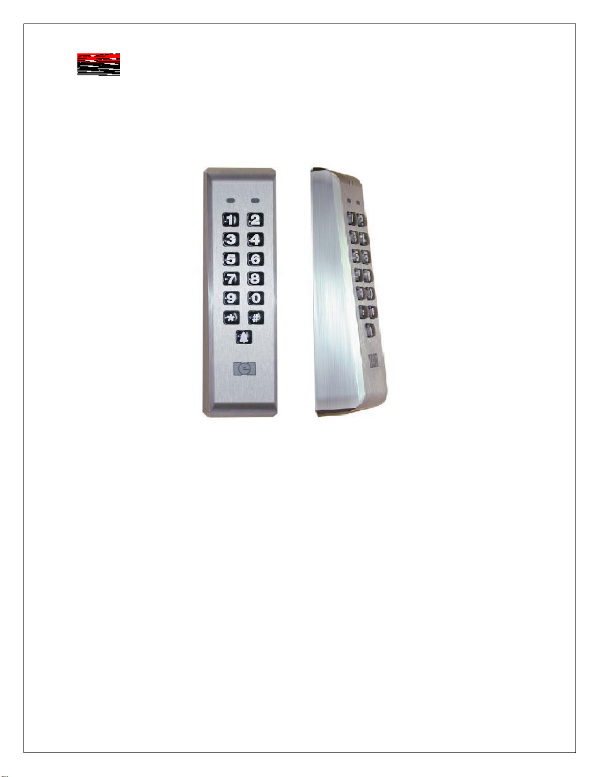
212iLM Mullion (ILLUMINATED WEATHER RESISTANT) Keypad
Stand Alone Keypad-Installation Manual
Features:
v120 User Capability
vIlluminated Hardened Keys
vProgrammable 00-99 Second Relay Activation Time
vRemote Trigger Input (REX)
vBell output (timed or continuous)
vDesigned for Heavy Traffic Application (greater than 1 million cycles)
vSurface Mount
vIndoor / outdoor Applications
vFully encapsulated
Installation:
qSection 1: Unpacking and checking the packing list
qSection 2: Mounting the 212iLM Mullion
qSection 3: Wiring the 212iLM Mullion
qSection 4: Power Up and System Defaults
qSection 5: Programming the 212iLM Mullion
qSection 6: Trouble Shooting
International Electronics, Inc.
427 Turnpike Street
Canton, Massachusetts 02021
6051344 Rev. 1.0
Page 2of 17
qSection 1: Unpacking and checking the packing list
Open the box, and inside you will find:
Keypad: (1) 212iLM Mullion keypad
Harnesses: (1) 8 Conductor wire harness
Wrenches: (1) Standard 5/64 allen wrench
Hardware: (1) Hardware Pack containing: (2) 8 x1¼” Panhead Slotted Machine Screw; (2) 8 x 1¼”
Round Head Wood Screw; (2) 6-8 x ¾” Plastic Anchor, (1) 212iLM mounting template.
Literature: (1) 212 Standalone Mullion Instruction Manual
Please check the contents of this package and verify all components in the packing list are present.
Taking this inventory will familiarize you with the components as well as ensure that you have a complete
parts list.
Tools required:
You will need a drill, drill bits1/8, 3/16 & 5/16 (for the plastic anchors), wire strippers, regular & small flat
blade screwdrivers, a marking pen or pencil, some heat shrinkable tubing (for the wire splices), a ruler or
measuring tape, silicone to seal any holes and possibly some electrical tape to hold the wires together or
the template in place.
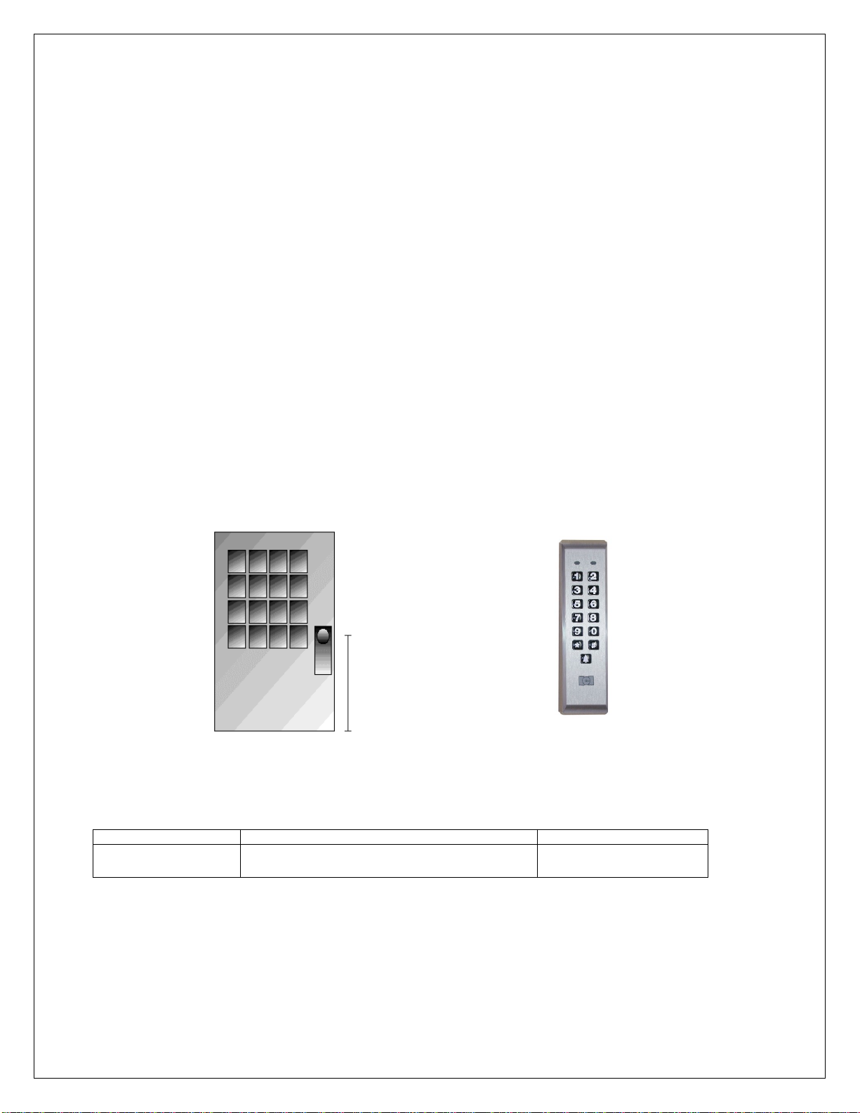
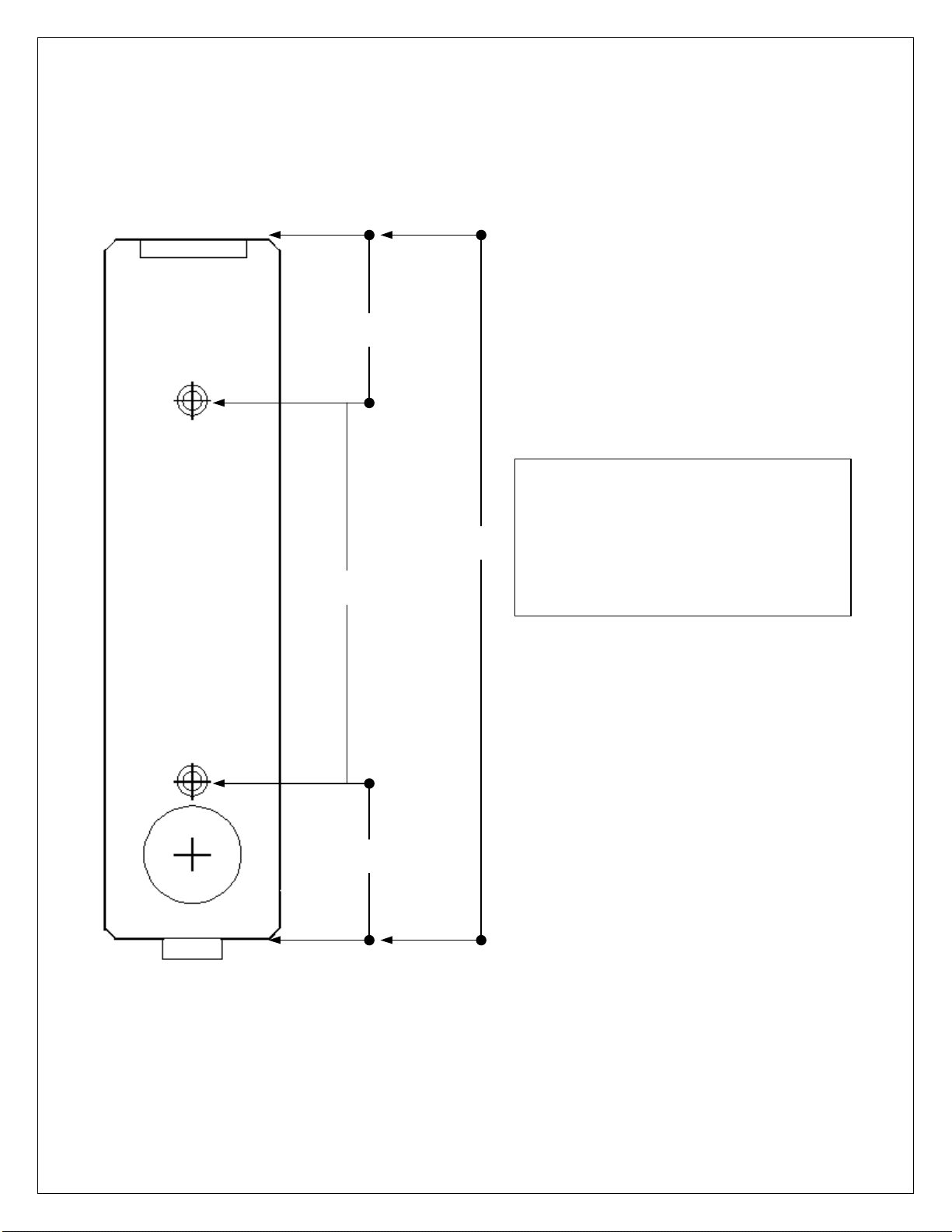
qSection 2: Mounting the 212iLM Mullion
212iLM Mullion Dimensions: 6 ½”L x 1 ¾”W x 1 1/8”D
Select the appropriate location for the 212iLM Mullion. Mounting height is the same for an electrical
switch, 48" on center. The 212iLM Mullion should be Surface Mounted with a 1/4” hole for the wires
centered approximately 5/8 of an inch underneath the center of bottom mounting hole (refer to the
included mounting template).
qSection 3: Wiring
Electrical Specifications:
Operating Voltages: Max Current Draw @ allowed voltages: Temperature Tolerance:
12-24V-AC/DC only
for input voltage. 53mA@12V, 72mA@24V; 94mA@12VAC,
103mA@16VAC, 108mA@24VAC Standard, -20° to 130°F.
*Tech note- Although the 212iLM will work with AC or DC voltage, it is recommended to use a filtered
and regulated power supply for it’s ability to maintain voltage and reduce the possibility of voltage spikes.
Suggested mounting
height is 48”

6051344 Rev. 1.0
Page 3of 17
1. Attach the 8-conductor wire harness to the plug in connector on the back of the 212iLM Mullion.
2. Next you will need to attach the relay wires (white/yellow, blue, and brown) to the wire run that is
connected to the locking device.
3. The Red and Black wires are connected to the power supply last, BEFORE the power is turned on.
Connect positive of the supply to the Red wire and negative to the Black wire.
212iLM Mullion: Wire Colors and Designations:
Pin Wire Color Signal Name Pin Wire Color Signal Name
1Red V in(+) 5Blue Main Relay Common
2Black V in(-) 6Brown Main Relay NO
3White/Black REX 7White Bell Relay Contact (A)
4White/Yellow Main Relay NC 8White Bell Relay Contact (B)
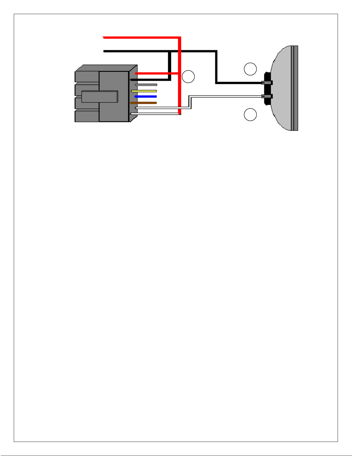
Wiring to a Magnetic Lock: (see below)
The 212iLM Mullion is equipped with a Form C, Dry contact relay. This means that there is no
voltage running through the relay (until you supply the common leg of the relay with voltage).
Situation 1:
If you are using a common power supply with the 212iLM Mullion and the Magnetic Lock, (that is to say if
you have only one power supply for both the 212iLM Mullion and the lock device), you need to run
voltage through the common (blue) wire on the 8 conductor wire harness of the 212iLM Mullion
Step 1: Splice together the Blue (common) wire from the 212iLM Mullion harness to the Red wire on the
212iLM Mullion harness and to positive voltage coming from the power supply.
Step 2: Connect the White /Yellow wire (normally closed) from the 212iLM Mullion harness to the Positive
connection on the Magnetic Lock.
Step 3: Splice together the Black wire on the 212iLM Mullion to the Negative connection on the Magnetic
Lock harness and to negative voltage coming from the power supply.
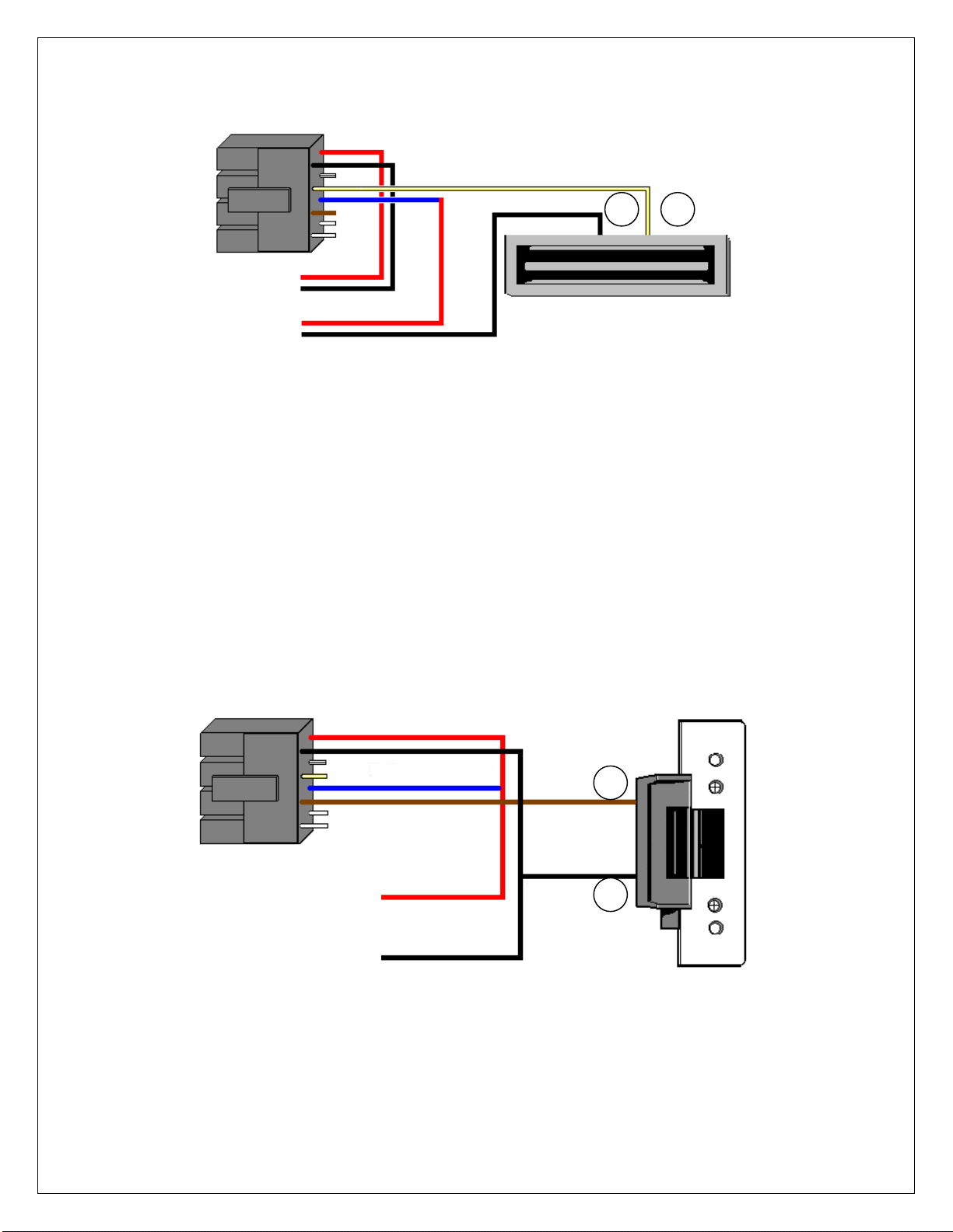
Example of Wiring to a Electro-Magnetic Lock Using a COMMON Power Supply:
Situation 2:
If you are using a separate power supply with the 212iLM Mullion and the Magnetic Lock, you need to
run voltage from the positive of the power supply to the common (blue) wire on the 8 conductor wire
harness of the 212iLM.
Step 1: Connect the Positive (red) wire on the 212iLM Mullion harness to Positive voltage coming from
the 212iLM power supply.
Step 2: Connect the Negative voltage wire on the 212iLM power supply to the Negative (black) voltage
wire on the 212iLM
Step 3: Connect the Blue (common) wire from the 212iLM harness to the Positive voltage on the lock
power supply
Step 4: Connect the Negative voltage coming from the lock power supply to the Negative connection on
the Magnetic lock.
Step 5: Connect the White/Yellow (normally closed) on the harness to the positive connection on
Magnetic Lock.
Blue =Common
To Power Supply V+
To Power Supply V-
White/Yellow = Normally Closed
Red
Black
1----
3----
5----
7----
----2
----4
----6
----8
_
+
212iLM
Wire
Harness
6051344 Rev. 1.0
Page 4of 17
Example of Wiring to a Electro-Magnetic Lock Using a SEPARATE Power Supply:
Wiring to an Electric Strike: (see below)
The 212iLM Mullion is equipped with a Form C, Dry contact relay on board. This means that there is
no voltage running through the relay (until you supply the common leg of the relay with voltage).
Situation 1:
If you are using a common power supply with the 212iLM Mullion and the Electric Strike, (that is to say if
you have only one power supply for both the 212iLM Mullion and the lock device), you need to run
voltage through the common (blue) wire on the 8 conductor wire harness of the 212iLM Mullion
Step 1: Splice together the Blue (common) Relay wire from the 212iLM Mullion harness to the Red wire
on the 212iLM Mullion harness and to positive voltage coming from the power supply.
Step 2: Connect the Brown (normally open) wire from the 212iLM Mullion harness to the Positive voltage
connection on the Electric door strike.
Step 3: Splice together the Black wire on the 212iLM Mullion to the Negative connection on the Electric
door strike harness and to negative voltage coming from the power supply.
Example of Wiring to an Electric Strike Using a COMMON Power Supply:
Blue =Common
To 212iLM V+
Power Supply V-
White/Yellow = Normally Closed
Red
Black
_
+
To Lock V+
Power Supply V-
212iLM
Wire
Harness
To Power Supply V+
To Power Supply V-
Blue = Common
Brown = Normally
open
Red
Black
_
+
212iLM
Wire
Harness

6051344 Rev. 1.0
Page 5of 17
Situation 2:
If you are using a separate power supply with the 212iLM Mullion and the Electric Strike, you need to run
voltage from the positive of the power supply to the Brown (normally open) wire on the 8 conductor wire
harness of the 212iLM.
Step 1: Connect the Positive (red) wire on the 212iLM Mullion harness to Positive voltage coming from
the 212iLM power supply.
Step 2: Connect the Negative voltage wire on the 212iLM power supply to the Negative (black) voltage
wire on the 212iLM power supply.
Step 3: Connect the Brown (normally open) on the harness to the positive connection on Electric Strike.
Step 4: Connect the Blue (common) wire from the 212iLM harness to the Positive voltage on the lock
power supply.
Step 5: Connect the Negative voltage coming from the lock power supply to the Negative connection on
the Electric Strike.
Example of Wiring to an Electric Strike Using a SEPARATE Power Supply:
Shunting a Normally Closed Zone: (see below)
Step 1: Connect the Blue (Common) Relay wire from the 212iLM Mullion harness to the Common
connection on the door position switch.
Step 2: Connect the Brown (Normally Open) Relay wire from the 212iLM Mullion harness to the Normally
closed connection on the Door position switch.
Example of Shunting a Normally Closed Zone
Red
Black
To Power Supply V-
To Power Supply V+
Blue = Common
Brown = Normally open
Red
Black
212iLM
Wire
Harness
Blue = Common
Brown = Normally
open
_
+
212iLM
Wire
Harness
To 212iLM V+
Power Supply V-
To Lock V+
Power Supply V-
6051344 Rev. 1.0
Page 6of 17
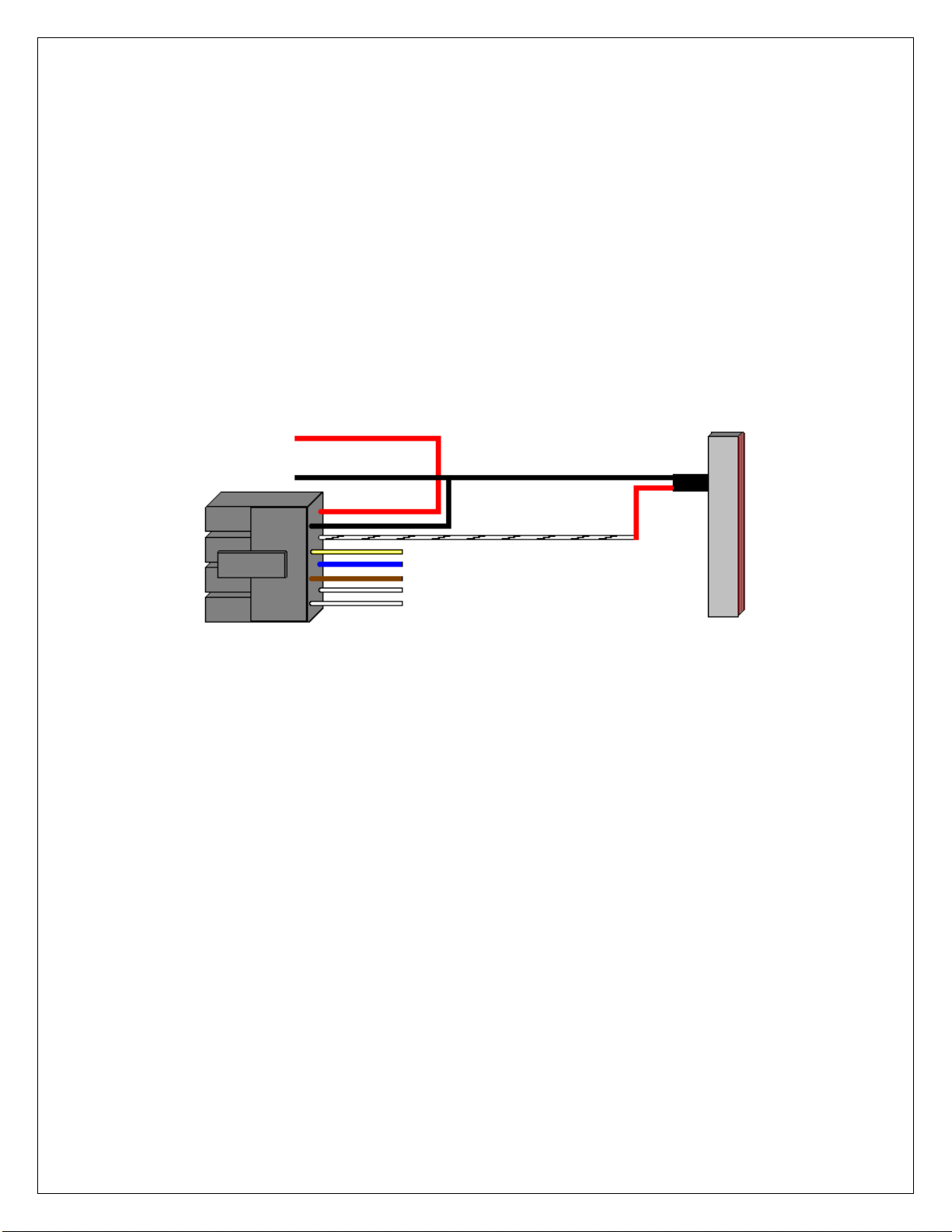
Wiring to a Request to Exit (Push to release):
The 212iLM Mullion keypad may be wired to accept an input from a remote-switching device. This is a
momentary input that will engage the main relay for the same amount of time that the master code is
programmed with. This input requires a normally open, momentary closure between the White with a
Black trace wire and the Black wire. The only time the REX won't follow the main relay time is if the
Master code has been programmed to latch the main relay. In this case, the REX will operate with the
default time of 5 seconds. You may wire in several devices parallel to release the door from different
locations but they must all be normally open devices. There is no programming required for this option.
The 212 iLM needs normally open DRY contacts to operate the relay with the REX input. If your remote exit
device sends voltage when it is pressed, you MUST connect an external relay to the wires coming from the
REX, then connect the 212iLM Mullion REX connections to the common and the normally open connections
on the external relay.
Step 1: Connect the White with Black trace wire on the 212iLM Mullion harness to the common
connection on the REX device.
Step 2: Splice a wire to the Black (negative) wire on the 212iLM Mullion harness and connect to the
Normally Open connection on the REX device.
Example of wiring to an IEI request to exit device (part #EZ-REX):
Wiring the Bell Button:
There are 2 white wires on the 8 conductor harness, an A(common) and a B(normally open) for the bell
button. This is a dry contact, normally open form A relay. Connect positive (from power) to common (A)
of the 212iLM wiring harness. Connect normally open (B) of the 212iLM harness to positive terminal of
bell or speaker. Then connect the negative of bell or speaker to the negative of the power supply.
Step 1: Connect the Black (Negative) wire from the 212iLM Mullion harness to the Negative connection
on the doorbell speaker and splice it into the negative wire from the power supply.
Step 2: Connect the White (Common-A) wire from the 212iLM Mullion harness to the Positive connection
on the doorbell speaker.
Step 3: Connect the White (Common-B) wire from the 212iLM Mullion harness to the Positive wire from
the power supply.
To Power Supply V+
To Power Supply V-
White/Black = Normally
Open REX Input
Black = Negative
Red
212iLM
Wire
Harness
6051344 Rev. 1.0
Page 7of 17
Example of wiring to a Bell or Speaker:
qSection 4: Power Up
Making the Power Connections: (The 212iLM Mullion is powered with 12-24 Volts AC or DC ONLY)
Step 1: Connect the Red (positive voltage input) wire from the 212iLM Mullion harness to the positive
voltage output connection on the power supply.
Step 2: Connect the Black (Negative voltage input) wire from the 212iLM Mullion harness to the negative
voltage output connection on the power supply.
Step 3: Plug in the power supply.
Upon power up, the 212iLM Mullion will cycle through the LED's from left to right twice to indicate proper
keypad operation. (If the LED's continue to flash, refer to the trouble shooting section of this manual on
page 14). The backlighting will now be on and will dim 15 seconds after the last keypress or 5 seconds
after the programming mode has been exited. The red LED should now be on. Perform the Self-Test by
pressing 7890#123456*. The LED’s will cycle from Green to Yellow to Red and then the sounder will
beep three times. Press 1234*and the main relay should energize for 5 seconds and the green LED
should light for the time the relay is open. After the relay closes, the green LED should turn off and the
red LED should come back on.
System Defaults:
The Door-Gard Keypad is designed for easy installation in a minimum amount of time. The following
default values have been factory programmed.
Master Code 1234
Audible Key Press Feedback On
Visual Key Press Feedback On
Keypad illumination Enabled
Keypad Dimming Enabled
Door bell select Enabled
Door bell duration Continuous
If it is necessary to change any of these defaults, please refer to the Programming Options Chart after
you have familiarized yourself with the programming section.
To Power Supply V+
To Power Supply V-
White (A) Common
Connection
White (B) Normally
Open Connection
Red
Black
_
+
+
212iLM
Wire
Harness

6051344 Rev. 1.0
Page 8of 17
qSection 5: Programming the 212iLM Mullion
The 212iLM Mullion supports 120 user codes that will energize the main relay. A user code is stored in
the memory of the 212iLM Mullion with an individual user location, and may be 1 to 6 digits in length.
Each user code has a corresponding user location. To help with the understanding of user locations,
think of them like shelves. The 212iLM Mullion has 120 shelves (user locations) in it, and each user code
gets put into its own shelf (user location). For example: the Master code (factory defaulted to 1234), is
always stored as user location 1. Every time a new user code is added, a new user location must be
used. To do any programming the 212iLM Mullion must be put into the Programming Mode. The keypad
will come out of programming after 45 seconds if no keys are pressed.
Step 1: Entering the Programming Mode.
Programming mode is accessed by entering the following command.
99 followed by the # key.
Next the current Master Code has to be entered. The default master code is 1234.
Then finish the command by pressing the *key.
Example: 99 # 1234 *(the yellow LED will flash to indicate it is in programming.)
NOTE: Entering an additional *at this time will exit programming mode.
If the programming command was done successfully, the 212iLM Mullion starts flashing the yellow
LED slowly, indicating that it is now in programming mode. If the yellow does not come on flashing,
that is an indication that the incorrect Master code was entered. (See the trouble shooting section of
this manual on page 14 if this does not happen.)
Step 2: Changing the Master Code.
The 212iLM Mullion comes with the factory programmed Master code of 1234. This may be
changed to any code that has 1 to 6 digits in length. The 212iLM Mullion also comes set from the
factory with a 5-second relay activation time that may be changed to any time from 01 to 99
seconds, or 00 to latch (toggle) the relay.
The 212iLM Mullion has to be in programming mode before you can change the Master code.
To Change the Master code:
Enter Programming Mode: 99# (Master code) *(Yellow LED flashing slowly).
Next enter user location "1" which is always the Master code’s user number followed by the # key.
Next enter in the new Master code followed by the *key (Yellow LED flashes rapidly).
Repeat the new Master code followed by the *key. (Yellow LED will flash slowly).
If the change was successful, the yellow LED will still be flashing.
Example: 1 # 4321 *4321 *
Continue programming or press the *key again to exit.
To Change the Main Relay Activation Time:
Enter Programming Mode: 99# (Master code) *(Yellow LED flashing slowly).
Next enter the relay activation time in a two digit format (01 to 99 seconds or 00 to toggle or latch the
main relay.) followed by the # key.
Next enter user location "1" which is always the Master code’s user number followed by the # key.
Next enter in the Master code followed by the *key (Yellow LED flashes rapidly).
Repeat the Master code followed by the *key. (Yellow LED Will flash slowly).
If the change was successful, the yellow LED will still be flashing.
Example: 08 # 1 # 4321 *4321 *(sets output to 8 seconds for the master code of 4321)
Example: 00 # 1 # 4321 *4321 *(sets output to toggle on, toggle off with a code of 4321.)
Continue programming or press the *key again to exit.
NOTE: All user codes will follow the main relay time that is programmed into the master code. If a toggle
code is entered as the master code, all user codes will toggle unless otherwise specified.

6051344 Rev. 1.0
Page 9of 17
Step 3: Adding or Changing User Codes.
User codes may be 1 to 6 digits in length.The 212iLM Mullion has to be in programming mode to add or
change users
Enter Programming Mode: 99#(Master code) *
Next enter the user location. (2, 3, 4, etc.) followed by the # key.
Now enter the new code followed by the *key (Yellow LED flashes rapidly).
Repeat the new code followed by the *key (Yellow LED flashes slowly).
If the change was successful, the yellow LED will still be flashing slowly. Codes entered in this fashion
hold the relay time programmed with the master code.
Examples: 2 # 6789 *6789 *
3 # 53780 *53780 *
4 # 23966 *239646 *
Continue programming or press the *key again to exit.
Step 4: Creating a User Code With a Different Time, or to Latch/Toggle the Main Relay.
The 212iLM Mullion has to be in programming mode to add or change users
A latching or toggle code is used to open the relay for an indefinite amount of time. This operates much
like a light switch. When you enter a latching user code, the Main relay will activate and stay opened until
the same code or another latching user code is entered to close the relay.
Enter Programming Mode: 99#(Master code) *
Next enter the relay time of "00" followed by the # key.
Next enter the user location. (2, 3, 4, etc.) followed by the # key.
Now enter the new code followed by the *key (Yellow LED flashes rapidly).
Repeat the new code followed by the *key (Yellow LED will flash slowly).
If the change was successful, the yellow LED will still be flashing slowly.
Examples: 00 # 12 # 7788 *7788 *
00 # 55 # 6632 *6632 *
00 # 93 # 78651 *78651 *
Continue programming or press the *key again to exit.
Adifferent output on the main relay may be desired for one or more users. For example, an individual
may require several extra seconds to open a door than everyone else. If the main relay is set for 5
seconds, that person may need 10 seconds. A different output time for individual users is programmed
this way.
Enter Programming Mode: 99#(Master code) *
Next enter the relay time of "10" followed by the # key.
Next enter the user location. (2, 3, 4, etc.) followed by the # key.
Now enter the new code followed by the *key (Yellow LED flashes rapidly).
Repeat the new code followed by the *key (Yellow LED will flash slowly).
If the change was successful, the yellow LED will still be flashing slowly.
Example: 10 # 12 # 7788 *7788 *
10 # 55 # 6632 *6632 *
20 # 93 # 78651 *78651 *
Continue programming or press the *key again to exit.

6051344 Rev. 1.0
Page 10 of 17
Step 5: Changing the 212iLM Mullion Feedback Options.
The 212iLM Mullion has two keypress feedback options that you may choose from. One is an audio feed
back. This will activate the on board sounder every time that a key is pressed. The other is a visual
feedback. This will flash the yellow LED on the front of the keypad every time that a key is pressed.
These two options are used to verify when a key has been pressed. Both of these options may be used
individually, together or not at all. They are enabled by default.
Audio Option:
Enter Programming Mode: 99# (Master code) *
Next press Command number 30 followed by the # key.
Next press "0" for the audio feedback option followed by the # key.
Next press "0" to Disable or "1" to Enable the audio option followed by the # key.
Next press the *key (Yellow LED flashes rapidly).
Next press the *key (Yellow LED will flash slowly).
Example: 30 # 0 # 0 # **(This will disable the sounder from activating every time a key is pressed).
Example: 30 # 0 # 1 # **(This will enable the sounder to activate every time a key is pressed).
Continue programming or press the *key again to exit.
Visual Option:
Enter Programming Mode: 99# (Master code) *
Next press Command number 30 followed by the # key.
Next press "1" for the visual feed back option followed by the # key.
Next press "0" to Disable or "1" to Enable the visual option followed by the # key.
Next press the *key (Yellow LED flashes rapidly).
Next press the *key (Yellow LED will flash slowly).
Example: 30 # 1 # 0 # **(This will disable the yellow led from activating every time a key is pressed).
Example: 30 # 1 # 1 # **(This will enable the yellow led to activate every time a key is pressed).
Continue programming or press the *key again to exit.
Step 6: Auto-Entry.
Auto entry is used to turn off the star *key. The user only needs to enter their code number without the
star key and the relay will activate for the programmed relay time. To use this feature, the user codes
must be the same length as the Master code. This feature is disabled by default.
Enter Programming Mode: 99# (Master code) *
Next press Command number 30 followed by the # key.
Next press "2" for the Auto-Entry option followed by the # key.
Next press "0" to Disable or "1" to Enable the Auto-Entry option followed by the # key.
Next press the *key (Yellow LED flashes rapidly).
Next press the *key (Yellow LED will flash slowly).
If the change was successful, the yellow LED will still be flashing slowly.
Example: 30 # 2 # 1 # **(This will remove the *key from the code).
Example: 30 # 2 # 0 # **(This will add the *key to the code).
Continue programming or press the *key again to exit.

6051344 Rev. 1.0
Page 11 of 17
Step 7: Doorbell Option:
When the doorbell feature is enabled there will be visual and audio keypress feedback for the bell button
but when the feature is disabled there will be no keypress feedback. This doorbell feature has two modes
of operation: timed and continuous. Timed will allow programming of the output for a specified number of
seconds with a single short press. The doorbell is set for continuous by default and output bell sounds for
as long as the button is pressed.
Enabling or disabling Doorbell Option:
Enter Programming Mode: 99# (Master code) *
Next press Command number 30 followed by the # key.
Next press "5" for the doorbell option followed by the # key.
Next press "0" to Disable or "1" to Enable the doorbell option followed by the # key.
Next press the *key (Yellow LED flashes rapidly).
Next press the *key (Yellow LED will flash slowly).
Example: 30 # 5 # 1 # **(This will enable the doorbell function).
Example: 30 # 5 # 0 # **(This will disable the doorbell function).
Continue programming or press the *key again to exit.
To set the Doorbell Option for continuous or timed operation:
Enter Programming Mode: 99# (Master code) *
Next press Command number 32 followed by the # key.
Next press "0" for the doorbell option followed by the # key.
Next press "0" for continuous (Or enter a time of 1 trough 99 for timed output.) doorbell operation,
followed by the # key.
Next press the *key (Yellow LED flashes rapidly).
Next press the *key (Yellow LED will flash slowly).
Example: 32 # 0 # 0 # **(This will enable the doorbell function for continuos output).
Example: 32 # 0 # 1 # **(This will enable the doorbell function for a 1 second output).
Example: 32 # 0 # 20 # **(This will enable the doorbell function for a 20 second output).
Continue programming or press the *key again to exit.
Step 8: Enabling or disabling keypad illumination or dimming:
The backlighting dims 15 seconds after the last keypress. It also dims 5 seconds after exiting
programming mode. This option is enabled by default.
To enable/disable keypad illumination:
Enter Programming Mode: 99# (Master code) *
Next press Command number 30 followed by the # key.
Next press "3" for the backlighting option followed by the # key.
Next press "0" to Disable or "1" to Enable the keypad illumination option followed by the # key.
Next press the *key (Yellow LED flashes rapidly).
Next press the *key (Yellow LED will flash slowly).
Example: 30 # 3 # 1 # **(This will enable keypad illumination).
Example: 30 # 3 # 0 # **(This will disable keypad illumination).

6051344 Rev. 1.0
Page 12 of 17
To enable/disable keypad dimming:
If keypad dimming option is set to zero, then the keypad will maintain full illumination at all times. This
option is enabled by default.
Enter Programming Mode: 99# (Master code) *
Next press Command number 30 followed by the # key.
Next press "4" for the dimming option followed by the # key.
Next press "0" to Disable or "1" to Enable the keypad dimming option followed by the # key.
Next press the *key (Yellow LED flashes rapidly).
Next press the *key (Yellow LED will flash slowly).
Example: 30 # 4 # 1 # **(This will enable keypad dimming).
Example: 30 # 4 # 0 # **(This will disable keypad dimming).
Continue programming or press the *key again to exit.
Step 9: Reset to Factory Default.
This command is used to erase the entire keypad memory, any programming done prior to this
step will be permanently erased including user codes, and it will reset the factory defaults.
When this command has been done successfully, the 212iLM Master code will return to the default of
1234 and the main relay will activate for 05 seconds.
The 212iLM Mullion has to be in programming mode to default it.
Enter Programming Mode: 99# (Master code) *
Next press Command number 46 followed by the # key.
Next press the "0" key five times followed by the # key.
Next press the "0" key five times followed by the # key.
Next press the *key (Yellow LED flashes rapidly).
Next press the *key (Yellow LED will flash slowly).
If the change was successful, the yellow LED will still be flashing slowly.
Example: 46 # 00000 # 00000 # **
Continue programming or press the *key again to exit.
If the Master code is not working or has been forgotten:
Power down the 212iLM Mullion and connect the White with Black trace wire to the Red wire and power
up the 212iLM Mullion. This will put the 212iLM Mullion into program mode indicated by the flashing
yellow LED. Next enter 46#00000#00000# **to default the keypad. Power down to remove the
White/Black wire from the Red wire.
Step 10: To Exit programming Mode:
Press the star (*) key.

6051344 Rev. 1.0
Page 13 of 17
Programming Options Chart
If the pre-programmed default values must be changed or additional functions are desired, the following
options may be programmed.
•Enter programming mode Press: 99 #(master code)*
The master default code is 1234 and the 212iLM must be in programming to make any changes.
•Changing the master code Press: 1 # (new code)*(repeat code)*
•Change the main relay activation time: Press: (relay time) # 1 # (mastercode)*(repeat code)*
All main relay times are entered in a 2-digit format. For example: 08 for eight seconds.
Example: Master code with an 8 second relay time: Press: (08) #1 #1234 *1234 *
•Add or change user codes Press: (user location) # (new code)*(repeat code)*
Codes entered in this fashion will hold the same relay time that the master code is programmed with. If the
relay time is changed after all other programming is done, the codes will not follow the master code for time.
You will have to either change time manually or reset defaults and reprogram. User locations are explained in
Section 5.
•Add a user to latch the main relay: Press: (00) # (user location) # (new code)*(repeatcode)*
•Add a user with a different output time on the main relay: Press: (relay time) # (user location) # (new
code)*(repeat code)*
Example: User code with a 8 second relay time Press: (08) #2 #1234 *1234 *
•Turn audible keypress feedback ON Press: 30 # 0 # 1 # **
•Turn audible keypress feedback OFF Press: 30 #0#0# **
•Turn visual keypress feedback ON Press: 30 #1#1# **
•Turn visual keypress feedback OFF Press: 30 #1#0# **
•To enable keypad illumination: Press: 30 # 3 # 1 # **
•To disable keypad illumination: Press: 30 # 3 # 0 # **
•To enable keypad dimming: Press: 30 # 4 # 1 # **
•To disable keypad dimming: Press: 30 # 4 # 0 # **
•To enable the doorbell function: Press: 30 # 5 # 1 # **
•To disable the doorbell function: Press: 30 # 5 # 0 # **
•To set the length of time for the bell for continuous operation: Press: 32 # 0 #0# **
•To set the length of time for the bell for timed operation Press: 32 # 0 # (time) # **
•Turn Auto-Entry ON (eliminates using the star key after a code) Press: 30 #2#1# **
•Turn Auto-Entry OFF Press: 30 #2#0# **
•Erase entire keypad memory and reset defaults: Press: 46 #00000 #00000 # **
For a detailed explanation of each option please refer to prior pages 7-11.

6051344 Rev. 1.0
Page 14 of 17
Section 6: Trouble Shooting.
Refer to this section if the 212iLM Mullion is not responding correctly to the operation outlined in this
instruction manual. The 212iLM Mullion has been designed to operate with 12-24 Volts AC or DC.
Verify that the voltage powering this keypad is within these parameters.
Situation 1: LED's are slowly cycling from right to left and the Backlighting is off.
Reason: The 212iLM Mullion has been designed to monitor for low voltage. Once the low
voltage has been detected, the keypad shuts down some of its options like
backlighting to ensure operation of the keypad until the problem can be attended to.
Solution: Check the output voltage of the power supply with a meter to verify the output voltage
rating listed for that device. If it is below the voltage threshold of 7.5 Volts AC or 9
Volts DC, you must increase the voltage to between 12-24 Volts.
Situation 2: LED's are rapidly cycling from left to right and the keypad has lost all
operation.
Reason: The 212iLM Mullion has been designed to monitor for over voltage. This is a very
"severe" condition and therefore significantly affects the keypad’s operation. Once
the over voltage has been detected, the keypad shuts down all operation and will not
operate until the voltage irregularity has been corrected.
Solution: Check the output voltage of the power supply with a meter to verify the output voltage
rating listed for that device. If it is over the voltage threshold of 35 Volts, you must
reduce the voltage to under 29 Volts.
Situation 3: The Master code is not allowing access to the programming mode.
Reason: There are a few reasons that this situation could occur. The most common is that the
Master code was programmed incorrectly. That is to say that someone entered a
user code into user number one. The Master code is always kept in memory with
user number "1" and users are in positions “2” through “120”.
The other reason this could happen is that the code was simply forgotten.
Solution: Power down the keypad, connect the white/black wire to the Red wire on the 212iLM
Mullion wire harness and power back up. The yellow LED will be flashing indicating
that the keypad is now in programming mode. Change the Master code by press 1 #
(New Master Code) *(Repeat Master Code) **. When finished with programming,
power down the unit, separate the white/black wire from the Red wire on the 212iLM
Mullion harness and power back up. The keypad is now ready to use.
Situation 4: No LED's are lit on the keypad
Reason: Power is not reaching the keypad.
Solution: With a meter check the voltage connection at the 212iLM Mullion keypad on the Red
& Black wires. Confirm that there is actually voltage at the keypad. If there is no
voltage reading at the keypad, use the meter on the power supply to verify that
voltage is leaving the power supply. If there is no voltage coming out of the power
supply, call the manufacturer of that power supply. If there is voltage at the power
supply, but not at the keypad, use the meter to test each of the wires for a break in
the wire. You may also use a 12-Volt Battery to power the 212iLM with, in order to
verify that it is functioning.

6051344 Rev. 1.0
Page 15 of 17
International Electronics Incorporated (IEI) warrants its products to be free
from defects in material and workmanship, when they have been installed in
accordance with the manufacturer’s instructions, and have not been modified or
tampered with. IEI does not assume any responsibility for damage or injury to person or
property due to improper care, storage handling, abuse, misuse, normal wear and tear,
or an act of God.
IEI’s sole responsibility is limited to the repair (at IEI’s option) or the replacement of the
defective product or part when sent to IEI’s facility (freight and insurance charges
prepaid), after obtaining IEI’s Return Merchandise Authorization. IEI WILL not be liable
to the purchaser or any one else for incidental or consequential damages arising from
any defect in, or malfunction of, it’s products.
This warranty shall expire two years after shipping date for Door Gard Keypads. Except
as stated above, IEI makes no warranties, either expressed or implied, as to any matter
whatsoever, including, without limitation to, the condition of its products, their
merchantability, or fitness for any particular application.
INTERNATIONAL
ELECTRONICS, INC.
427 Turnpike Street
Canton, MA 02021 U.S.A.
Phone:(781) 821-5566
(800) 733-9502 Sales in MA
(800) 343-9502 Sales
FAX: (781) 821-4443
Visit our Web Site at www.ieib.com

6051344 Rev. 1.0
Page 16 of 17
NOTES: IEI suggests that you make a record of your installation for future reference.
6051344 Rev. 1.0
Page 17 of 17
1 7/16”
1 7/16”
3 3/8”
6 1/4”
Diameter of the mounting holes is: 11/64
Diameter of the wiring holes is: 7/8
This product is designed as a surface
mountable product. The access hole for the
wires is determined by the amount of wires
that will run through the mounting surface.
Table of contents
Other International Electronics Keypad manuals


Popular Keypad manuals by other brands

Elko
Elko iNels RF KEY - 40 quick start guide

Key 7
Key 7 SA850-A21 installation manual

Bandini Industrie
Bandini Industrie GiBiDi DCD 100 Instructions for installation

hager
hager 2916 installation instructions

Honeywell
Honeywell 6270 - Ademco TouchCenter Keypad quick guide

NAPCO
NAPCO GEM-RP1CAE KEYPAD manual


Bosch
Bosch D1265 owner's manual

PRAGMATIC COMMUNICATIONS SYSTEMS
PRAGMATIC COMMUNICATIONS SYSTEMS CATS-KP user manual

ANXELL
ANXELL DG-750 quick start guide

Detection Systems
Detection Systems DS7400Xi reference guide

HR Matic
HR Matic HR PAD NEW VERSION INSTRUCTION MANUAL AND WARNINGS

iPort
iPort xPRESS quick start guide