Hilberling PT-8000 User manual

HF / VHF Transceiver
PT-8000 A·B·C
Operating Manual
Version 1.0

–– This page is intentionally blank ––

i
HF / VHF Transceiver
Hilberling PT-8000
A
/
B
/
C
Operating Manual
PT-8000, HN-8000 and T9
are
developed and manufactured in the EU
by
Hilberling GmbH
Kieler Strasse 53
24768 Rendsburg
Germany
Logo and name of Hilberling GmbH are registered trademarks

ii Precautions / Content
Important
Read and save this Operating Manual carefully before attempting to operate the HF/VHF PT-8000
transceiver. This manual contains important safety and operating instructions for the transceiver.
Precautions
WARNING HIGH VOLTAGE! NEVER touch an antenna or internal antenna connector during
transmission. This may result in an electrical shock or burn of your skin.
NEVER apply AC to the DC socket (13.8V and 100V for PT-8000 B) on the transceiver rear
panel. This will ruin the transceiver and may cause fire.
NEVER allow any object touch any internal parts or connectors on the rear panel of the
transceiver. This could cause electrical shock and severe injury.
NEVER expose the PT-8000 A/B to precipitation like rain or any liquid nor operate the
transceiver in excessively dusty or very humid environment.
NEVER allow children or any unauthorized persons to operate the transceiver.
AVOID placing and using the transceiver in areas with temperatures below -15°C or above +50°C.
AVOID placing the transceiver against a wall. This may inhibit proper air circulation and could cause
overheat.
USE CARE when connecting the transceiver to a linear amplifier. Set the PT-8000 A/B RF-output level
to less than the linear amplifier’s maximum input level to prevent amplifier damage.
USE CARE when not operating the transceiver with Hilberling T-9 microphone. Others may have
different pin assignments and connecting to the transceiver may cause damage to the transceiver and
the microphone.
For U.S.A. only:
CAUTION: Changes or modifications to the PT-8000 A/B not expressively authorized by
Hilberling GmbH could void your authority to operate this transceiver under FCC regulations
For Canada only:
This class digital apparatus complies with Canadian ICES-003.
Cet appareil numériqué de la classe est conformé à la norme NMB-003 du Canada.
Copyright© 2007 by Hilberling GmbH

PT-8000
A
/
B
/
C Operating Manual iii
Table of content
Part A Introduction
1 PT-8000 Series Of Transceivers - Characteristics
1.1 Receiver (RX) .......................................................................................................................................................A–1
1.2 Transmitter (TX) ..................................................................................................................................................A–2
1.3 Power Supplies And Growth Potential ....................................................................................................................A–2
1.4 Technical Specifications ........................................................................................................................................A–3
1.5 Operating Limitations ...........................................................................................................................................A–4
Part B Installation
3 Unpacking And Installation Considerations
3.1 Unpacking ...........................................................................................................................................................B–1
3.2 About This Manual ...............................................................................................................................................B–1
3.3 Initial Installation Considerations ...........................................................................................................................B–2
3.4 Antenna Considerations ........................................................................................................................................B–2
4 Connectors
4.1 Rear Panel ...........................................................................................................................................................B–3
4.2 Connectors At Front Panel ....................................................................................................................................B–6
5 Power Supply
5.1 General ...............................................................................................................................................................B–7
5.2 Rear Panel ...........................................................................................................................................................B–8
5.3 Front Panel ..........................................................................................................................................................B–9
6 Zubehör
6.1 Microphone Hilberling T9 ....................................................................................................................................B–10
6.2 Wiring/Cables ....................................................................................................................................................B–10
6.3 Pull Out Instruction ............................................................................................................................................B–11
6.4 Operating Manual ...............................................................................................................................................B–11
6.5 Handles .............................................................................................................................................................B–11
Part C Installation And Operation
7 Installation And Connections ........................................................................................................ C–1
8 Front Panel Controls, Display And Their Function
8.1 Front Panel Controls .............................................................................................................................................C–2
8.2 Display ................................................................................................................................................................C–3
8.3 Clustered Front Panel Controls ..............................................................................................................................C–5
8.4 Controls With Integrated Push-Button Function And Controls For Adjustments .........................................................C–6
8.5 Side Panel Controls ..............................................................................................................................................C–7
8.6 Keys With LED and LEDs ......................................................................................................................................C–8
9 MAIN- And SUB-RX Operations ..................................................................................................... C–9
10Modes Of Operation (MODE) ....................................................................................................... C–11
10.1 SSB / CW (Single Side Band / Continuous Wave) ................................................................................................C–11
10.1.1 SSB Single Side Band .....................................................................................................................................C–11
10.1.2 CW Continuous Wave ....................................................................................................................................C–12
10.2 ISB (Independent Side Band) ............................................................................................................................C–13
10.3 AM / FM (Amplitude Modulation / Frequency Modulation) ...................................................................................C–14
10.4 DATA Transmission ...........................................................................................................................................C–16
11Selecting Frequencies ................................................................................................................. C–17
11.1 BAND Select .....................................................................................................................................................C–17
11.1.1 HF BANDS .....................................................................................................................................................C–16
11.1.2 VHF BANDS ...................................................................................................................................................C–18
11.1.3 Transverter Operation ....................................................................................................................................C–19
11.2 Numerical Frequency Input ...............................................................................................................................C–21
11.3 CHANNEL Operation ..........................................................................................................................................C–23
11.4 MAIN Tunung Knob ...........................................................................................................................................C–25
11.5 STEP-VFO Control .......................................................................................................................................C–26

iv Precautions / Content
11.6 VFO Management .............................................................................................................................................C–27
11.7 SPLIT Operation .........................................................................................................................................C–29
11.8 RIT / XIT .........................................................................................................................................................C–30
11.9 LOCK Function .................................................................................................................................................C–31
12Memory Operation (MEM) ........................................................................................................... C–32
13Filter Bandwith And Shift Function (WIDTH / Shift) .................................................................. C–34
14Notch Functions / Noise Reduction / Noise Blanker
14.1 Notch Filter Functions (IF- And DSP-Notch) ........................................................................................................C–36
14.1.1 IF-NOTCH .....................................................................................................................................................C–36
14.1.2 DSP-NOTCH ..................................................................................................................................................C–36
14.2 Noise Reduction ...............................................................................................................................................C–37
14.3 Noise Blanker ...................................................................................................................................................C–37
15Squelch Function ......................................................................................................................... C–38
16RX Gain Control (AGC / RF-GAIN) .............................................................................................. C–39
17Frequency Scanning (SCAN) ....................................................................................................... C–41
18Calibration, Voice Recorder ......................................................................................................... C–42
18.1 Calibration Menu ..............................................................................................................................................C–43
18.1.1 Reference Calibration .....................................................................................................................................C–43
18.1.2 Preselector Calibration ...................................................................................................................................C–44
18.2 Brightness Of Display (DIM)...............................................................................................................................C–46
18.3 Recording Functions (Voice Recorder).................................................................................................................C–47
19Metering Of PT-8000 (METER) .................................................................................................... C–48
20Basic Settings RX/TX .................................................................................................................. C–49
21Transmitter Controls ................................................................................................................... C–54
21.1 ZERO-BEAT ......................................................................................................................................................C–54
21.2 MIC .................................................................................................................................................................C–54
21.3 PROC ...............................................................................................................................................................C–54
21.4 TX-PWR ...........................................................................................................................................................C–55
21.5 VOX .................................................................................................................................................................C–55
21.6 ANTI-TRIP .......................................................................................................................................................C–55
21.7 DELAY (of VOX).................................................................................................................................................C–55
21.8 Monitoring Function (MONITOR) .......................................................................................................................C–55
21.9 TX-DELAY (CW) ................................................................................................................................................C–56
21.10 KEY SPEED .....................................................................................................................................................C–56
22Operating Auxiliary Equipment ................................................................................................... C–56
Part D Annex
23Software Update (TBD).................................................................................................................. D–1
24Circuit Description ......................................................................................................................... D–3
25Block Diagram .............................................................................................................................D–11
26Maintenance (TBD) ......................................................................................................................D–12
27Troubleshooting (TBD).................................................................................................................D–12
28Cross Reference (TBD).................................................................................................................D–12
29Glossar (TBD)...............................................................................................................................D–12
30List Of Pictures And Tables (TBD)................................................................................................ D–12
31List Of Menus (TBD)..................................................................................................................... D–12
32 Warranty Terms (TBD) ................................................................................................................ D–12

A–1
Part A Introduction
1 PT-8000
S
ERIES
O
F
T
RANSCEIVERS
-
C
HARACTERISTICS
Hans Hilberling, DK7LG, the founder of Hilberling GmbH and a veteran Amateur Radio operator and RF
engineer specified the design requirements of his “dream-transceiver”:
1. It must include a single high-quality transmitter with two independent receivers covering the
entire HF and VHF spectrum.
2. VHF operation must be an integral part of the design, not an afterthought. VHF performance
must match HF.
3. Its operational frequency range must be easily expandable through the use of transverters.
4. It must include independent sideband (ISB) capability.
5. The design must incorporate both analogue and digital signal processing, using the best of both
technologies.
6. It must provide high output power on HF through the use of modern, efficient HF-MOSFETs at
50 V (PT-8000A) and 100 V (PT-8000B) drain voltage .
The result is the PT-8000 series of HF/VHF-Transceivers featuring cutting-edge design!
1.1 Receiver (RX)
Each of the two identical receivers are double super-heterodyne Rx with 70.7 MHz 1st intermediate
frequency (IF) and 10.7 MHz 2nd IF. The PT-8000 incorporates high quality, state-of-the-art receiver
design, including:
1. An automatically tuned preselector which is a series tuned circuit from 1.8 to 30 MHz. The main
inductance is based on a T-200 toroid. Research has shown that the IMD characteristics
correlate with the mass of the material and the transformation ratio used. The IP3 of this
preselector is outstanding +50dBm. The series circuit is tuned through software by 5 inductor
taps (5 bit) and an 8-bit capacitor set. A noise generator is used to tune and store all settings in a
table. In order to enhance the filter characteristics the circuit is operating at approximately 3
ohms – there are down and up transformers at the input and output.
2. Precision-matched first and second mixers with third intercept points at +40 dBm. The mixers are
designed specifically for Hilberling by Synergy Microwave, a respected name in the industry.
3. Three 6-pole roofing filters at 2.7 kHz, 6 kHz and 12 kHz for outstanding inband IMD and BDR
performance.
4. Six hybrid amplifiers from LF to VHF with third intercept points at +50 dBm
5. The first local oscillator is designed with quadruple microwave VCOs which offer excellent phase
noise characteristics: -130 dBc/Hz at 10 kHz and –145 dBc/Hz at 50 kHz. The first local oscillator
design features microwave VCOs designed specifically for Hilberling. It includes a 0.05 ppm
reference oscillator with organic DDS. Phase noise suppression is enhanced by means of 300 Hz
crystal filtering.
6. The PT-8000 uses ultra-sharp 10.7 MHz IF filtering. The key to the receiver’s performance is its
seven 16-pole ladder filters working in combination with DSP filters in the 10.7 MHz second IFs
of each receiver. The filter shape factor is an excellent 1.3 at 2.4 kHz. The same high-quality
filters are used in the transmitter stages as well. 17 of these filters are used in the PT-8000.

A–2 Part A Introduction
1.2 Transmitter (TX)
The transmitter frequency scheme follows the receiver design. In addition, the transmitter is capable of
transmitting two sidebands independently (ISB-operation). For example, one can transmit an SSTV
signal on LSB and a voice (phone) comment on USB for example. The transmit power is 100 or even
600 Watts with enhanced filtering:
1. The PT-8000 transmitter stage starts with a Class-A 10 W driver amplifier operating from 1.8 to
150 MHz. IMD3 is less than –50 dB at 2.5 W.
2. The 100 W power amplifier utilizes a 50 V HF-MOSFET which is actually a “Gemini” package
hence comprising two HF-MOSFETs working push-pull (SD2932). This HF-MOSFET is capable
to dissipate 500 Watts and delivering up to 300 Watts output power. The PA of the PT-8000A is
limited to 100 Watts hence presenting a signal with outstanding IMD characteristics.
3. The 600 W final amplifier includes a pair of high-efficiency (70%) SD3933 HF-MOSFETs — a
breakthrough in transmitter design.
4. The PT-8000 assures clean output thanks to innovating filtering, including the use of additional
three 70.7 MHz roofing filters in the transmitter stages.
5. A diplexer-filter guarantees optimum performance of the finals. An automatic antenna tuner
(ATU) is an integral part of the output design. In terms of power handling capability of these
components there is no difference between the 100/600 W models.
6. For VHF operation (144 MHz to148 MHz) a 13,8 V VHF-MOSFET (RD70HVF1) is used,
designed to deliver 25 watts output.
1.3 Power Supplies And Growth Potential
The HN-8000 consists of switching power supplies with full power factor correction (PFC) as demanded
by many energy suppliers. It is capable of delivering up to 1,000 W 13.8/50 V DC-power for the PT-
8000 A. The HN-8000 designed for the PT-8000 B is capable of delivering up to 2,000 watts DC power
at 13,8/100 V supply voltage. Both power supplies are rugged in design and deliver ample power for the
PT-8000 series. The DC-input power can easily monitored with the large front panel power meter.
As your operating horizons expand and new demands occur, your PT-8000 will respond:
1. The PT-8000 is the ideal platform for exploring the world above 50 MHz. Not only does it offer
outstanding 6 and 2 meter transceiver performance, the PT-8000 is designed with UHF and
microwave transverters in mind. It offers 1 Hz frequency resolution and the ability to connect
transverters to both receivers simultaneously.
2. The PT-8000 provides output taps at the first and second IFs for analysis, monitoring and
experimentation.
3. The PT-8000 firmware is easily upgraded – as described in Part D of this manual.

PT-8000
A
·
B
·
C User Manual A–3
1.4 Technical Specifications
RX: Double Super Heterodyne 1st IF 70.7MHz and 2nd IF 10.7MHz
Range 9 kHz ... 54 MHz / 110 ... 170 MHz (MAIN / SUB)
Xtal-Filter 1st and 2nd IF (BW) 70.7 MHz (2.7 kHz / 6.0 kHz / 12.0 kHz) MAIN 10.698 / SUB 10.702 MHz (0.5 ... 6.0 kHz / 12.0 kHz)
Sensitivity @ 10 dB S+N/N AM FM SSB ISB CW
200 kHz ... 1.8 MHz 6 kHz / 2 µV 12 kHz / 0.5 µV 2.4 kHz / 1 µV 3.1 kHz / 0.5 µV 0.5 kHz / 0.5 µV
1.8 MHz … 54 MHz 6 kHz /1.2 µV 12 kHz / 0.25 µV 2.4 kHz / 0.22 µV 3.1 kHz / 0.4 µV 0.6 kHz / 0.15 µV
110 MHz ...170 MHz 6 kHz / 1.0 µV 12 kHz / 0.22 µV 2.4 kHz / 0.22 µV 3.1 kHz / 0.22 µV 0.6 kHz / 0.18 µV
IP3 @ 20 kHz 0.5 MHz ... 170 MHz +39 dBm
IMD DR3 @ Spacing @ 2 kHz 86 dB; @ 5 kHz 97 dB; @ 10 kHz 104 dB; @ 20 kHz 108 dB; @ 100 kHz 113 dB;
Image Rejection And Spurious Signal Suppression >>70 dB
Digital Signal Processing (DSP) Variable bandwidth for 2nd IF 10.7 MHz Xtal filters; multiple automatic audio notch filtering;
Almost undistorted audio when engaging automatic noise reduction through enhanced algorithms
AF-Output 4.8 Watt (2 x 2.4 Watt MAIN / SUB); additional speaker in HN-8000 and optional alternate speaker
TX: Independent Transmission Of 2 Sidebands – ISB
Range 1.8 MHz … 54 MHz; 144 MHz … 148 MHz (160, 80, 60, 40, 30, 20, 17, 15, 12, 10, 6, 2 m-Band)
Mode /Output (max.-HF; 6m) AM / AME / ISB / FM SSB/CW IMD3 (PEP) IMD3 (Class A)
PT-8000 A 100 Watt 100 Watt -40 dB 2.5 Watt / -50 dB
PT-8000 B 125 Watt 600 Watt -36 dB 2.5 Watt / -50 dB
PT-8000 C 2.5 Watt 10 Watt -36 dB 2.5 Watt / -50 dB
VHF PT-8000 A / B / C 25 Watt 25 Watt -36 dB 2.5 Watt / -50 dB
Carrier Suppression SSB / ISB – 70 dB / PEP
Opposite Sideband Suppression SSB / ISB – 70 dB / @1 kHz
FM Frequency deviation ± 3 kHz FMN; repeater operations with variable shift 0 ... 2 MHz
General
Memory Channels Organized in 3 banks @ 99 channels; automatic scanning mode
Frequency Stability 0.05 ppm from 10C° to 60 C°; Reference Clock 20 MHz adjustable in 12 mHz steps; Ext. Clock 10 MHz
Environmental Conditions Temperatures 10C° to 60C° Avoid high humidity (operating below dew point) and dusty operating
conditions
Antenna Connectors N-type 2 x HF 50 Ohm; 1 x VHF 50 Ohm
Dimensions (H x B x T) approximately 175 mm x 425 mm (543 mm including handles) x 465 mm
Weight approximately. 52 lbs
HN-8000 Switching Power Supply for PT-8000A/B/C
Mains
Power Requirement
90 … 260 VAC Power Factor Correction (PFC)
117 VAC / 13 Amp.; 240 VAC / 7 Amp.
PT-8000A DC 13.8 V / 10 Amp. , 50 V / 10 Amp.
PT-8000B DC 13.8 V / 10 Amp., 100 V / 12 Amp.
Dimensions approximately 175 mm x 225 mm x 440 mm
Weight approximately 15 lbs
Accessories
All Versions Cable set (AC, DC, Ground, Speaker)
Ham Version - Desk Microphone T9 600 Ohm @ 1kHz, dynamic, RFI-proof, kidney-shaped acoustic response
- set of plugs
Specification Professional Version
TX-range according to customers specification; extended temperature range; UL-listed and more.
For additional information and special requirements please contact Hilberling GmbH Table 1

A–4 Part A Introduction
1.5 Operating Limitations
TBD

B–1
Part B Installation
3 U
NPACKING
A
ND
I
NSTALLATION
C
ONSIDERATIONS
3.1 Unpacking
Examine your PT-8000 for signs of damage during shipping. Should any damage be apparent please
take appropriate measures (contacting your carrier). We recommend to retain all packing material – it
might be used for shipment of the radio.
Listed below are the hardware and all accessories delivered with your PT-8000. Make sure you´ve
received and unpacked everything:
Quantity Description Picture
1 Power Supply HN-8000 6
1 Microphone T9 7
1 AC Power Cord HN-8000 8
1 DC Power Cord HN-8000PT-8000 9
1 Ground Wire HN-8000PT-8000 10
1 Speaker Cabel HN-8000PT-8000 11
1 Phono Plug 6.3mm
2 Phono Plug 3.5mm
1 DB-25 Male Plug
1 DA-15 Male Plug
2 DE-9 Male Plug
1 RS232 Cabel For Software Update 12
4 Handles 15
1 Operating Manual
Table 2
3.2 About This Manual
The PT-8000 represents primarily state of the art analog RF-design. However digital signal processing
and microprocessor controlled circuits add to this transceiver in a synergistic way. Hence, features and
functions can be easily improved and/or tailored to customer needs through updating the Hilberling
GmbH firmware using the RS232 interface. Owners will be informed about firmware upgrades as they
are released – please have a look at chapter Part D.
The latest version of PT-8000 Operating Manual will be posted as a PDF-document at Hilberling GmbH
website (www.hilberling.de)
In this handbook the following signs and symbols are used:
The STOP sign indicates a warning that must be obeyed for safety reasons
This sign indicates an important explanation or a specific advice which
should be obeyed
An additional information or explanation is indicated this way

B–2 Part B Installation
3.3 Initial Installation Considerations
When selecting the place for operating the PT-8000 bear in mind the general limitation concerning
environmental conditions as outlined in the specifications and the cautions at the very beginning of this
manual.
Select a power outlet that is capable to handle the power requirements especially for the PT-8000B.
Connect your PT-8000 to a proper ground system – which is important for optimum operation of any HF
transceiver – especially when operating high power either with the PT-8000B or using an external
amplifier. In the past, a ground connection to a copper water pipe was often used for this purpose.
Recent revisions to the National Electric Code has made this practice a code violation. Bear in mind that
modern supply water installations utilize plastic pipe – which do not function grounding purposes. Never
use a gas or electric pipe since the connection could cause an explosion or electric shock.
A good grounding system not only prevents electrical shock but also helps to ensure trouble free
operation and will diminish television and broadcast interference (TVI/BCI).
For your convenience you might raise the PT8000 and the HN-8000 by unfolding and locking into
position the front stand under the cabinet as shown on the picture.
Allways handle the PT-8000 with care – consider the weight of more than 50 lbs, please!
3.4 Antenna Considerations
Standing wave ratio (SWR) may increase significantly when using an antenna outside of the specific
frequency range for which it is tuned. The final power amplifier will operate at peak performance only
when its load is resistive – i.e. the SWR is close to 1.0. Therefore the PT-8000 is equipped with an
automatic antenna tuner (ATU) which does not actually tune the antenna. The ATU instead matches the
feedline to the final amplifiers so they always “see” and SWR of 1.0. The ATU has its limits – tuning
mismatches with SWR greater than 2.0 become difficult and will exceed the capabilities of the ATU.
Using a tuned or resonant antenna with 50 Ohm impedance at the feedpoint for the specific frequencies
is highly recommended. The purpose of the ATU is to ensure that a resonant antenna can be used at the
limits of the band selected with optimum performance of both PT-8000 and antenna system. Never try to
hook up a symmetrical open feeder line (balanced, twin-lead, ladder line etc,) directly to the PT-8000.
Instead use 50 ohm coaxial feeders only. The connectors supplied on the PT8000 are all Type N.
With the ATU it is acceptable to use a broadband antenna system like a log periodic or T2FD system
which trade wide bandwidth for an SWR ranging as high as 2.0.
Picture 1
PT-8000
A
·
B
·
C User Manual C–3
4 C
ONNECTORS
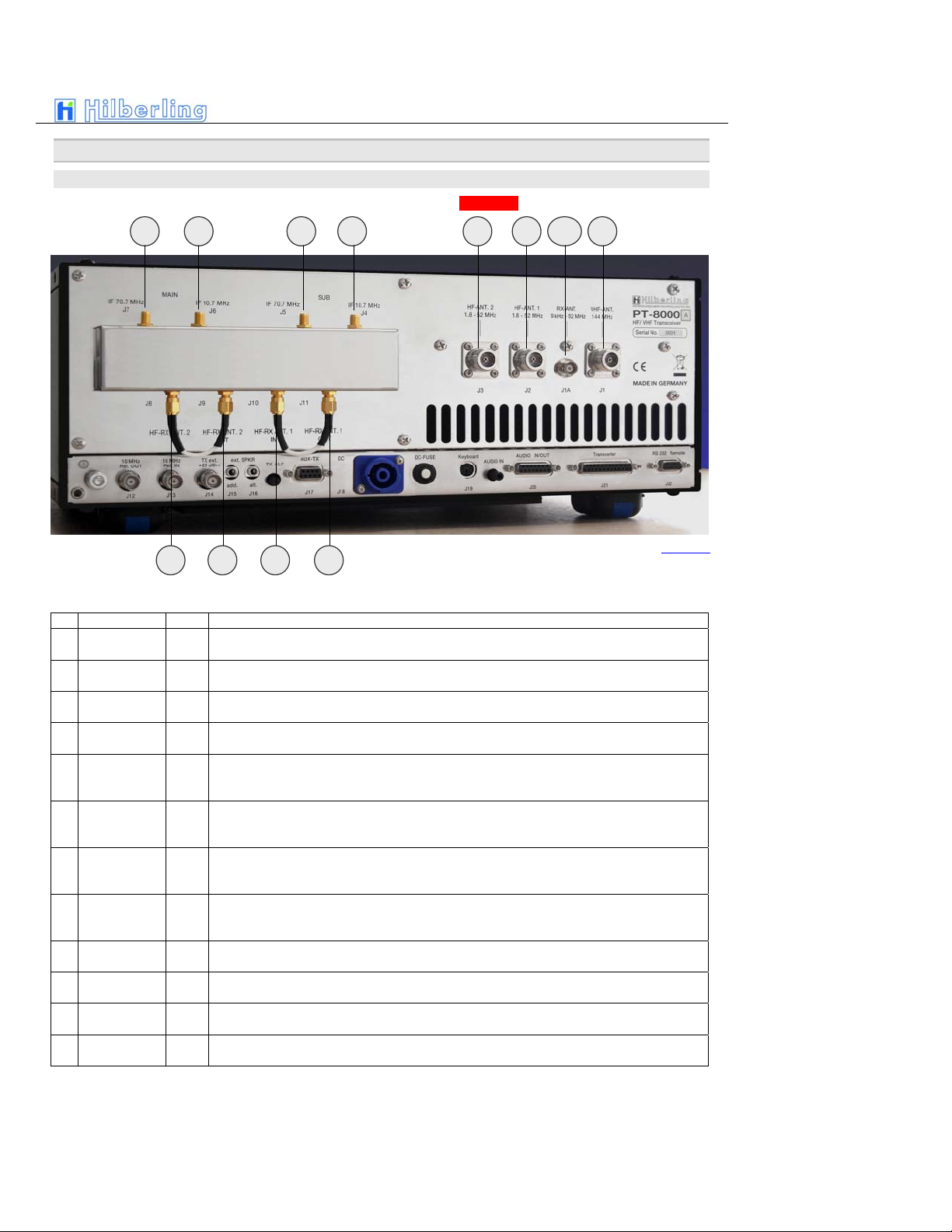
4.1 Rear Panel
A variety of jacks are accessible at the rear panel. Please unfold Picture 1 - pointing out all connections.
HF/VHF-Connection Sockets J1 ... J11
No NAME Type Description
J1 VHF-ANT
110 … 170 MHz
N-Type Connect a VHF-Antenna for 110 to 170 MHz (RX) and 144 to 148 MHz (TX)
J1A RX-ANT
9 kHz ... 54 MHz
BNC Connect a VLF/HF/VHF-antenna for receive only from 9 kHz … 52 MHz / 54 MHz (USA). For DUPLEX
mode the input may stay open during transmission.
J2 HF-ANT.1
1.8 ... 52 MHz
N-Type Connect VLF/HF/VHF-antenna #1 frequency coverage 9kHz ... 52 MHz / 54 MHz (USA)
J3 HF-ANT.2
1,8 ... 52 MHz
N-Type Connect VLF/HF/VHF-antenna #1 frequency coverage 9kHz ... 52 MHz / 54 MHz (USA)
J4
IF 10.7 MHz
SUB
SMA
Output 1st IF 70.7 MHz of SUB-RX. The output is tapped after the 1st mixer and the IF-amplifier HV20-200
– thus being broadband when preselector is disengaged
J5
IF 70.7MHz
SUB
SMA Output 2nd IF 10.7 MHz of SUB-RX. The output is tapped after the 2nd mixer and IF-notch and noise
blanker circuit. No AGC and no 10.7MHz xtal filter at that point. Thus bandwidths are determined by roofing
filter.
J6
IF 10,7 MHz
MAIN
SMA
Output 1st IF 70.7 MHz of MAIN-RX. The output is tapped after the 1st mixer and the IF-amplifier HV20-200
– thus being broadband when preselector is disengaged
J7 IF 70.7MHz
MAIN
SMA Output 2nd IF 10.7 MHz of MAIN-RX. The output is tapped after the 2nd mixer and IF-notch and noise
blanker circuit. No AGC and no 10.7MHz xtal filter at that point. Thus bandwidths are determined by roofing
filter.
J8 HF-RX ANT. 2
IN
SMA J6/J7 disconnects RX (MAIN/SUB) from HF-ANT.2 – J6 is either connected to J7 or to output of external
equipment (QRM-eliminator, ANT-switch panel etc.)
J9 HF-RX ANT. 2
OUT
SMA HF-ANT.2 (in RX-mode) either connected to J6 or to input of external equipment (QRM-eliminator, ANT-
switch panel etc.)
J10 HF-RX ANT. 1
IN
SMA J8/J9 disconnects RX (MAIN/SUB) from HF-ANT.1 – J8 is either connected to J9 or to output of external
equipment (QRM-eliminator, ANT-switch panel etc.)
J11 HF-RX ANT. 1
OUT
SMA HF-ANT.2 (in RX-mode) either connected to J8 or to input of external equipment (QRM-eliminator, ANT-
switch panel etc.)
Table 3
J1J2J3J5J6 J4J7
Picture 2
J11J10
J9J8
J1A

C–4 Part C Installation And Operation
Connection Sockets J12 … J22
No NAME Type Description
Banana Plug 4mm Grounding wire – must be connected toHN-8000 power supplyE
M6 Grounding stud – must be connected to HN-8000 power supply and to station ground
J12 10 MHz Ref.
OUT
BNC Output for an external 10 MHz reference signal (clock) for synchronization of PT-8000 to
other equipment
J13 10 MHz Ref.
IN
BNC Input of internal/external 10MHz reference clock (internal: derived from 20 MHz system
clock with 0.05 ppm) for synchronization of external equipment to PT-8000
J14 TX ext.
+20 dBm
BNC TX external output (1.8…148 MHz). Level is +20 dBm to drive transverter or external
power amplifier
J15 ext. SPKR
add.
EIA-453 / IEC 60603-11
Phone Plug / TRS 3.5mm
Additional external speaker output. Use to connect the speaker at HN-8000 in addition to
built in speaker
J16 ext. SPKR
alt.
EIA-453 / IEC 60603-11
Phone Plug / TRS 3.5mm
Alternate external speaker output. Use to connect an alternate speaker to the built in
system
J17 AUX-TX
(PTT/ALC)
DE-9
(D-Sub 9pol)
J18 DC
IN
CliffCon
4-pol
Power connector for interconnection cable to HN-8000 power supply
J19 Keyboard
mini-DIN
PS/2 Connector
To be implanted later.
J20 AUDIO
IN/OUT
DA-15
(D-Sub 15pol)
To be implanted later.
J21 Transverter
DB-25
(D-Sub 25pol)
To be implanted later.
J22 Remote
RS 232
DE-9
(D-Sub 9pol)
Interface to update firmware of PT-8000
Table 4
E
J12 J13 J14 J16 J17 J18 J19 J20 J21 J22J15
Picture 3
PT-8000
A
·
B
·
C User Manual C–5
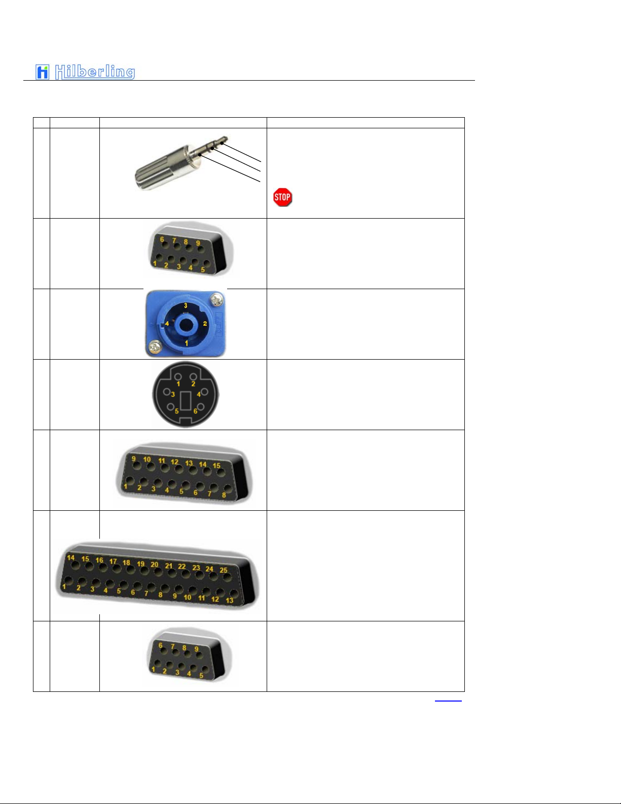
Wiring of J15 … J22
Nr. Name Typ Function And Outline
J15
J16
ext. SPKR
add.
ext. SPKR
alt.
Connect an additional (PT-8000 speaker will stay ON) or an
alternate speaker (PT-8000 speaker will be OFF)
1Tip + audio output (4,5 W max)
2Ring + audio output
3Sleeve GND
Caution: Using mono type plugs will shorten the
audio output and may damage the
transceiver
J17 AUX-TX
(PTT/ALC)
To be implanted later.
J18 DC
IN
PT-8000A PT-8000B PT-8000C
1(2-)13,8 VDC 13,8 VDC 13,8 VDC
2(1+) 50 VDC PA <Not Connected> <Not Connected>
3(1-) GND GND GND
4(2+) <Not Connected> 100 VDC PA <Not Connected>
J19 Keyboard
To be implanted later.
J20 AUDIO
IN/OUT
To be implanted later.
J21 Transverter
To be implanted later.
J22 Remote
RS 232
1<Not Connected> 6<Not Connected>
2RS232 TX 7RS232 RTS
3RS232 RX 8<Not Connected>
4RS232 DTR 9<Not Connected>
5GND
Table 5
C–6 Part C Installation And Operation
Miscellaneous
DC-Fuse 13.8 V DC circuit breaker for final PA rated 13,8 V / 25 Amp. for PT-8000C and
50 V / 15 Amp. or 100 V / 15 Amp. for PT-8000A/B
TX-ALC Sensitivity of ALC input (J17, pin 6) from external PA to reduce TX power out.
AUDIO IN Sensitivity of Audio data input (J20, pin 2) – rated 0 dBm.
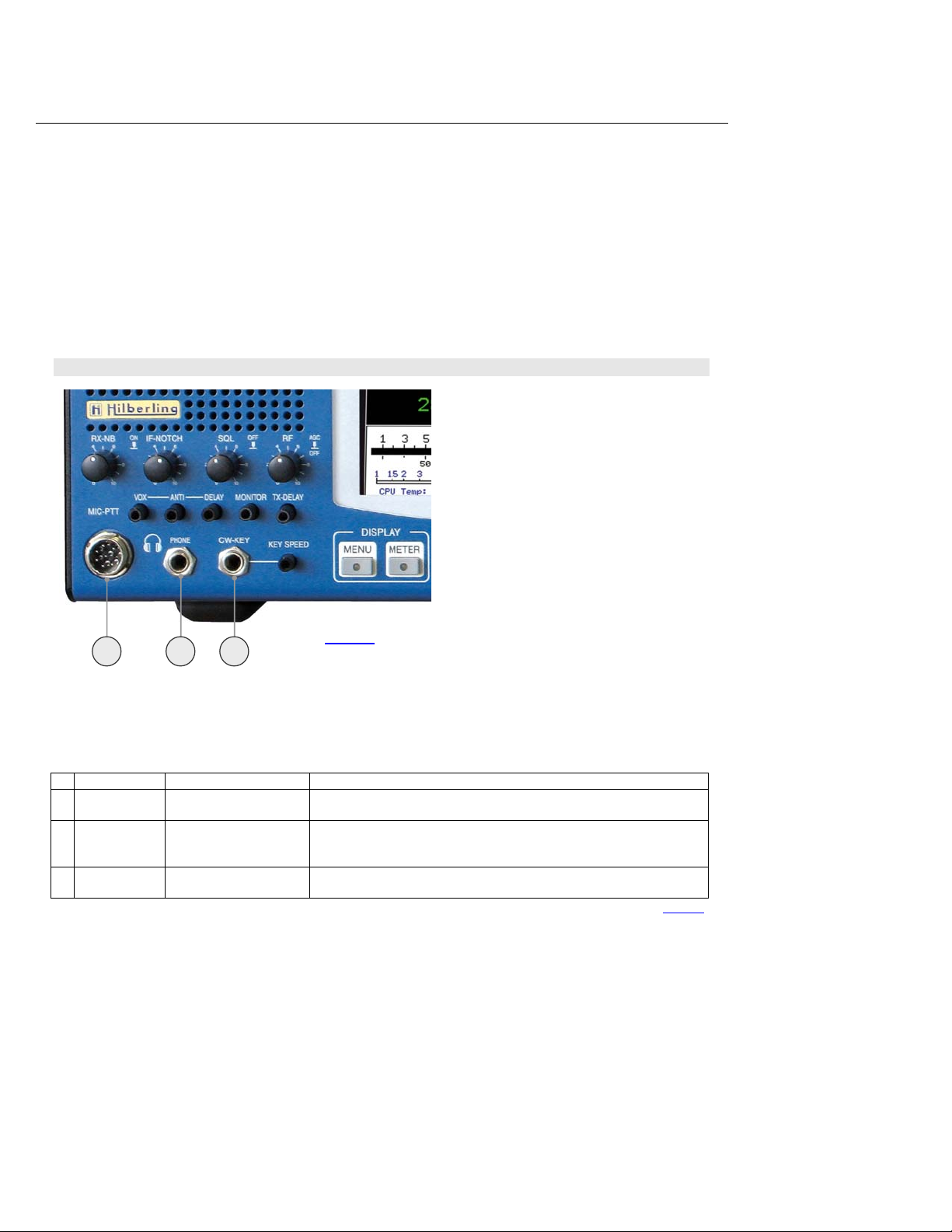
4.2 Connectors At Front Panel
Connection Sockets 1 ... 3
Nr. Name Typ Beschreibung
1 MIC-PTT
Microphone Socket
8-pol
Microphone connector for Hilberling T9 and Data input 0 dBm
2 PHONE
EIA-453 / IEC 60603-11
TRS 6.3 mm
Headphones low impedance (8 Ω). When plugged in the speaker(s) will be cut off.
NOTE: pushing the volume controls for MAIN and SUB will switch on the speaker(s)
momentarily
3 CW-KEY
EIA-453 / IEC 60603-11
TRS 6.3 mm
Keyer for CW
Table 6
1 2 3 Picture 4

PT-8000
A
·
B
·
C User Manual C–7
Wiring
Nr. Name Typ Funktion und Anschlussbelegung
1 MIC-PTT
0 dBm
1MIC-Audio
2PTT
3RX-MAIN Audio (headset)
40 dBm IN
5MIC IN +DC
6RX-SUB Audio (headset))
7MIC-GND
8PTT-GND
2 PHONE
1Tip + Audio OUT
2Ring + Audio OUT
3Sleeve GND
NOTE: Audio for PHONE is derived from audio preamplifier
especially designed for phone operations.
Caution: Using mono type plugs will shorten the
audio output and may damage the
transceiver
3 CW-KEY
1Tip DOT CW-Key
2Ring DASH <Not Connected>
3Sleeve GND GND
STATUS: Keyer ON Keyer OFF
Table 7
5 P
OWER
S
UPPLY
5.1 General
Each model PT-8000 A/B is equipped with its appropriate power supply all named HN-8000. The only
difference in appearance for the PT-8000A-model and the PT-8000B-model is the final amplifier DC
input power instrument at the front panel.
The HN-8000 is a switching power supply with industry standard. It complies with special regulations in
some countries regarding power factor compensation (PFC).
Operating voltages from the mains can be in the range of 90 VAC to 260 VAC without any degradation in
output power. Only the efficiency will vary slightly. The HN-8000 operating temperature is controlled by
up to 4 fans (PT-8000B). The HN-8000 accompanied with the PT-8000A and PT-8000B delivers 50 VDC
@ 15Amps and 100 VDC @15 A for the high power B-model.
5.2 Rear Panel
Electret Mic
Dynamic Mic

C–8 Part C Installation And Operation
Connection Sockets J1 ... J5
Miscellaneous
AC-FUSE Circuit breaker for AC mains at rear panel plug J5 rated 16 A @ 90 … 270 V AC
5.3 Front Panel
Nr. Name Type Description
J1 AC IEC-60320-C13 Input main power 90 – 270V AC
J2/3 13,8 V DC Banana Plug 4 mm + Clamp Auxiliary output 13.8V DC
Banana Plug 4 mm Grounding wire – must be connected to PT-8000 transceiver
E
M6 Grounding stud – must be connected to PT-8000 transceiver and to station ground.
J4 SPKR 8 ΩEIA-453 / IEC 60603-11
Phonostecker / TRS 3.5 mm Input for built in speaker from PT-8000 J15 or J16
J5 DC CliffCon
4-pol
Power connector for interconnection cable to PT-8000 J18.
Table 8
E J4 J5
J1
J2
J3
Circuit breaker for AC
Picture 5

PT-8000
A
·
B
·
C User Manual C–9
Miscellaneous
DC FUSE Circuit breaker for DC AUX at rear panel banana plugs J2/J3 rated 5 A @ 13.8 V DC
6 A
CCESSORIES
ON/OFF for DC Low Power
DC AUX
ON/OFF
DC Power Amplifier
DC-Fuse
AUX Power Meter
The power meter indicates
the DC input power of the
final power amplifier – hence
computation of efficiency
could be easily done by
comparing RF-power out as
indicated on PT-8000 display
and DC-input shown here.
Picture 6

C–10 Part C Installation And Operation
6.1 Microphone Hilberling T9
Best suited for all voice operations is the Hilberling T9 microphone especially
designed for the PT-8000.
Isolated from any mechanical vibrations and designed to be used from more
closer as well as from greater distance it will always guarantee high fidelity
audio and if desired an extra punch to the signal.
Impedance is 600 Ω@ 1kHz. The acoustic characteristic is kidney-shaped.
6.2 Wiring/Cables
AC-line voltage cable for HN-8000; length appr. 1,70 m
DC-cable HN-8000PT-8000; length appr. 1,10 m
Ground cable HN-8000PT-8000; length appr. 1,50 m
Speaker cable HN-8000PT-8000; length appr. 1,50 m
BILD fehlt RS232-data cable to connect a PC; length appr. 1,80 m
6.3 Pull Out Instruction
Picture 7
Picture 8
Picture 10
Picture 11
Bild 12
Picture 9
This manual suits for next models
3
Table of contents
Other Hilberling Transceiver manuals


