Hilberling PT-8000A User manual

HF / VHF Transceiver
PT-8000A
Operating Manual
Version 2.00.33

Copyright-notice to the ring binder title
All Figure rights reserved by: Bundeswehr / PIZ Marine, DGzRS and Hilberling GmbH

i
HF / VHF Transceiver
Hilberling PT-8000A
Operating Manual
PT-8000A, HN-8000 and T9
are
developed and manufactured in the EU
by
Hilberling GmbH
Kieler Strasse 53
24768 Rendsburg
Germany
Logo and name of Hilberling GmbH are registered trademarks
Distribution of the complete Document is desired
However, each partial copy or distribution is prohibited
Errors and changes excepted

ii
IMPORTANT NOTE AND PRECAUTIONS
Important
Read and save this Operating Manual carefully before attempting to operate the HF/VHF PT-8000A
transceiver. This manual contains important safety and operating instructions for the transceiver.
Precautions
WARNING HIGH VOLTAGE! NEVER touch an antenna or internal antenna connector during
transmission. This may result in an electrical shock or burn of your skin by high-frequency.
NEVER apply AC to the DC socket on the transceiver rear panel. This will ruin the transceiver and
may cause fire.
NEVER allow any object touch any internal parts or connectors on the rear panel of the
transceiver. This could cause electrical shock and severe injury.
NEVER expose the PT-8000A to precipitation like rain or any liquid nor operate the transceiver in
excessively dusty or very humid environment.
NEVER allow children or any unauthorized persons to operate the transceiver.
AVOID placing and using the transceiver in areas with temperatures below -15°C or above +50°C. If the
environment temperature drops so low that the dew point is undercut, avoid operating before the devices
are dried completely.
AVOID placing the transceiver and the power supply against a wall. This may inhibit proper air circulation
and could cause overheat. Do not cover any air inlets and outlets at top, bottom and rear panel of the
devices.
USE CARE when connecting the transceiver to a linear amplifier. Keep in mind the performance limits or
operating ranges of electrical connectors and interfaces. Set the PT-8000A RF-output level to less than the
linear amplifier’s maximum input level to prevent amplifier damage.
USE CARE when not operating the transceiver with Hilberling T9 microphone. Others may have different
pin assignments and connecting to the transceiver may cause damage to the transceiver and the
microphone.
Copyright © 2008-2013 by Hilberling GmbH

PT-8000A Operating Manual v2.00.33 iii
TABLE OF CONTENT
Important Note And Precautions ii
Table of Content iii
Federal Communications Commission (FCC) Statement vi
3 Introductory Notes
3.1 Scope Of Delivery .................................................................................................................................... 1
3.2 About This Manual .................................................................................................................................. 1
3.3 Notes On Locating ................................................................................................................................... 2
3.4 Antenna Considerations / Antenna Tuner .................................................................................................. 3
4 Connectors PT-8000A
4.1 Connectors at Rear Panel ......................................................................................................................... 4
4.1.1 HF/VHF Connectors J1 - J11 ........................................................................................................... 4
4.1.2 Connection Sockets J12 - J22 and Operating Elements ..................................................................... 5
4.1.3 Wiring of J15 - J21 ........................................................................................................................ 6
4.2 Connectors at Front Panel ........................................................................................................................ 7
4.2.1 Connection Sockets 1 - 3 ............................................................................................................... 7
4.2.2 Wiring .......................................................................................................................................... 7
5 Power Supply HN-8000
5.1 General Description ................................................................................................................................. 8
5.2 Connectors at Rear Panel / Connection Sockets J1 up to J4 ......................................................................... 8
5.3 Operating and Display Elements at Front Panel .......................................................................................... 9
6 Accessories
6.1 Microphone Hilberling T9 ......................................................................................................................... 9
6.2 Wiring / Cables ....................................................................................................................................... 9
6.3 Operating Manual and Software/Documention CD .................................................................................... 10
7 Installation / Initial Operation
7.1 Introduction ......................................................................................................................................... 11
7.2 Cable Connectors .................................................................................................................................. 11
7.3 Initial Settings ...................................................................................................................................... 11
8 Operating and Display Elements
8.1 Main Operating and Display Elements ..................................................................................................... 12
8.2 TFT-Display .......................................................................................................................................... 13
8.3 Clustered Front Panel Controls ............................................................................................................... 15
8.4 Controls with Integrated Push-Button Function and Controls for Adjustments ............................................. 16
8.5 Side Panel Controls (Level Adjustments) .................................................................................................. 17
8.5.1 Input Level –Left Hand Side ........................................................................................................ 17
8.5.2 Output Level –Right Hand Side .................................................................................................... 17
8.6 Pushbuttons With LED Status Display ...................................................................................................... 18
8.7 LED Status Display ................................................................................................................................ 19
9 MAIN- and SUB-RX Operations 20
10 Modes of Operation MODE 22
10.1 Single Side Band and Continuous Wave SSB / CW ................................................................................ 22
10.1.1 SSB Single Side Band ............................................................................................................... 22
10.1.2 CW Continuous Wave .............................................................................................................. 23
10.2 AM / FM Amplitude Modulation / Frequency Modulation ........................................................................ 24
10.2.1 Repeater Mode –How to Set the Repeater Frequency Shift ........................................................... 25
10.2.2 Repeater Mode –TX Frequency Display ....................................................................................... 25
10.3 DATA Transmission (Digital Operation Modes) ....................................................................................... 26
11 Selecting Frequencies 27
11.1 Select with BAND Keys ......................................................................................................................... 27
11.1.1 HF Amateur Radio Bands ........................................................................................................... 27
11.1.2 VHF Amateur Radio Bands ......................................................................................................... 28
11.1.3 Transverter Operation ................................................................................................................ 30
11.2 Numerical Frequency Input ENTER ..................................................................................................... 32

iv
11.3 Channel Operation
11.3.1 Recall of Stored Frequencies CHANNEL ...................................................................................... 34
11.3.2 Storage of Frequencies MEM .................................................................................................... 36
11.4 VFO Main Tuning Knob (
active
RX) and SUB VFO Tuning Knob (RX
in the Background
) .............................. 38
11.5 STEP VFO Control ................................................................................................................................ 39
11.6 VFO Mangement ................................................................................................................................. 40
11.7 SPLIT Operation .................................................................................................................................. 42
11.8 RIT / XIT Operation ............................................................................................................................. 43
11.9 Locking VFO Settings LOCK ................................................................................................................ 44
12 Filter Bandwidth and Shift Function FILTER WIDTH / SHIFT 45
12.1 Filter Bandwidth DSP Off .......................................................................................................................46
12.2 Filter Bandwidth DSP On .......................................................................................................................46
13 Notch Filter / Noise Reduction / Noise Blanker NOTCH / NR / NB
13.1 Notch Filter: IF-Notch and DSP Multi Notch .......................................................................................... 47
13.1.1 IF NOTCH Filter ......................................................................................................................... 47
13.1.2 DSP Multi NOTCH Filter („digital“ MNF) ........................................................................................ 47
13.2 DSP Noise Reduction NR .................................................................................................................... 48
13.3 Noise Blanker NB ............................................................................................................................... 48
14 Squelch SQL 49
15 RX Gain Control AGC / RF-GAIN
15.1 Automatc Gain Control AGC ................................................................................................................ 50
15.2 Manual Gain Control RF-GAIN ............................................................................................................. 51
16 Storage Frequency Scanning SCAN
temporary disabled
52
17 Speaker / Calibration / Display / Voice Recorder MENU 53
17.1 RX–Speaker Allocation Audio NORM / SPLIT ......................................................................................... 53
17.2 Calibration of Internal Reference REFERENCE CALIBRATION ................................................................. 54
17.3 Brightness of Display DIM .................................................................................................................. 55
17.4 NF Recording VOICE RECORDER ......................................................................................................... 56
18 Scale Select METER 57
19 Basic Settings RX/TX 58
19.1 RX Settings ......................................................................................................................................... 58
19.1.1 HF: Antenna Select / Preamplifier / Preselector / Attenuator / IF-2 Filters ....................................... 58
19.1.2 HF: Attenuator / IF-2 Filter Select ............................................................................................... 59
19.1.3 VHF: Preamplifier PRE AMP / DC on Antenna OUT DC AMP ........................................................ 60
19.1.4 VHF: IF-2 Filter Select ................................................................................................................ 61
19.2 TX Settings ......................................................................................................................................... 62
19.2.1 Leveler TX Audio LEV ............................................................................................................... 62
19.2.2 Equalizer Operation TX-Audio EQ .............................................................................................. 63
19.2.3 Keyer Select .............................................................................................................................. 64
19.2.4 TX Filter Select / TX Shift Select .................................................................................................. 65
19.2.5 TX Signal Settings ..................................................................................................................... 66
20 Transmitter Controls 58
20.1 Antenna Tuner .................................................................................................................................... 67
20.1.1 Activate TUNER ....................................................................................................................... 67
20.1.2 Start Re-Tuning Cycle START..................................................................................................... 67
20.1.3 Permanent Transmit Operation TX / ON .................................................................................... 67
20.2 ZERO-BEAT ......................................................................................................................................... 68
20.3 Microphone Sensitivity MIC (Gain) ....................................................................................................... 68
20.4 Compression TX Audio PROC .............................................................................................................. 68
20.5 Transmit Power Control TX-PWR ......................................................................................................... 69
20.6 VOX Operation .................................................................................................................................... 69
20.6.1 VOX Threshold .......................................................................................................................... 69
20.6.2 VOX ANTI-TRIP Activating Suppression ..................................................................................... 70
20.6.3 VOX DELAY Hold Time ............................................................................................................. 70
20.7 Monitoring TX Signal MONITOR .......................................................................................................... 70
20.8 Fall Time TX for CW TX-DELAY ........................................................................................................... 70
20.9 Keying Speed CW KEY SPEED ............................................................................................................. 70

PT-8000A Operating Manual v2.00.33 v
Appendix
A1 IF Monitor Software (Windows®Program)
A1.1 Introduction .................................................................................................................................... A1-1
A1.2 Hardware Requirements ................................................................................................................... A1- 1
A1.3 Setup Software ................................................................................................................................. A1- 1
A1.4 Installation of the IF Monitor Program ................................................................................................ A1-1
A1.5 Connect PT-8000A to PC by Audio Cable ............................................................................................ A1-2
A1.6 Start and set up the Program ............................................................................................................ A1-2
A1.6.1 Program Window ................................................................................................................... A1-3
A1.6.2 Automarker and Marker .......................................................................................................... A1- 3
A1.6.3 Peak Hold .............................................................................................................................. A1-4
A1.6.4 Sample Rate and Buffer Setup ................................................................................................. A1-4
A1.6.5 Signal Level Adjustment .......................................................................................................... A1-5
A1.6.6 Signal Level and Panorama Width Scaling ................................................................................. A1-8
A1.6.7 Waterfall Chart ...................................................................................................................... A1-9
A2 Firmware Update and Update Software (Windows®Program)
A2.1 Preliminary Note .............................................................................................................................. A2-1
A2.2 Introduction .................................................................................................................................... A2-1
A2.3 Requirements and Procedure ............................................................................................................ A2-1
A2.4 Setup Software and Firmware ........................................................................................................... A2-2
A2.5 Install Update Program on PC ........................................................................................................... A2-2
A2.6 Connect PT-8000A to PC by USB Data Cable ....................................................................................... A2-2
A2.7 Start and set up the Update Program ................................................................................................. A2-3
A2.7.1 Manual COM Port Setting ........................................................................................................ A2-3
A2.7.2 Select Firmware ..................................................................................................................... A2-4
A2.8 Get PT-8000A ready to update .......................................................................................................... A2-5
A2.9 Update of MAIN-CPU ........................................................................................................................ A2-7
A2.10 Update of RX- and ANT-Tuner-CPU ................................................................................................ A2-10
A3 Technical Documents
A3.1 Technical Data ................................................................................................................................. A3- 1
A4 Customer Information
A4.1 User Information
German only
.......................................................................................................... A4- 1
A4.2 Warranty Terms
German only
............................................................................................................ A4- 1
A4.3 Disposal Scheme
German only
........................................................................................................... A4- 2
A5 Lists
A5.1 Index .............................................................................................................................................. A5- 1
A5.2 List of Figures .................................................................................................................................. A5- 3
A5.3 List of Tables ................................................................................................................................... A5- 6
A5.4 Glossary .......................................................................................................................................... A5- 7

vi
FEDERAL COMMUNICATONS COMMISSION (FCC) STATEMENT
The Hilberling PT-8000A was tested and found to be in compliance with 47 CFR, Part 15 of the FCC
Rules, as an unintentional radiator and as a generic receiver. These limits are designed to provide
reasonable protection against harmful interference in a residential installation.
FCC ID: V84PT8000
This device complies with Part 15 of the FCC rules. Operation is subject to the following two
conditions:
(1) this device may not cause harmful interference, and
(2) this device must accept any interference received, including interference that may cause
undesired operation.
CAUTION: Changes or modifications to the PT-8000A not expressly approved by Hilberling GmbH could
void your authority to operate this transceiver under FCC regulations

PT-8000A Operating Manual v2.00.33 1
3 INTRODUCTORY NOTES
3.1 Scope Of Delivery
Examine your PT-8000A for signs of damage during shipping. Should any damage be apparent please
take appropriate measures (contacting your carrier). We recommend to retain all packing material –it
might be used for shipment of the radio.
Listed below are the hardware and all accessories delivered with your PT-8000A. Make sure you have
received and unpacked everything:
Quantity
Description
Fig.
1
Power Supply HN-8000
6
1
Microphone T9
7
1
AC Line Voltage Cable (Power Grid ⬄HN-8000)
8
1
DC Power Cable (HN-8000 ⬄PT-8000A)
9
1
Ground Cable (HN-8000 ⬄PT-8000A)
10
1
Speaker Cable (HN-8000 ⬄PT-8000A)
11
1
Data Cable (PC/Notebook ⬄PT-8000A)
12
1
Phono Plug 6,3mm
1
DB-25 Male Plug (DSUB 25-pol)
1
DA-15 Male Plug (DSUB 15-pol)
1
DE-9 Male Plug (DSUB 9-pol)
1
Operating Manual
13a
1
Software CD
• PT-8000A IF Monitor Program (Windows®)
• PT-8000A Update Program (Windows®)
• Operating Manual (PDF)
13b
Tab. 1
3.2 About This Manual
The PT-8000A represents primarily state of the art analog RF-design. However digital signal processing
and microprocessor controlled circuits add to this transceiver in a synergistic way. Hence, features and
functions can be easily improved and/or tailored to customer needs through updating the Hilberling
GmbH firmware using the USB interface (please have a look at Appendix A2).
2
In this manual the following signs and symbols are used:
The STOP sign indicates a warning that must be obeyed for safety reasons.
This sign indicates an important explanation or a specific advice which should be obeyed.
An additional information or explanation is indicated this way.
3.3 Notes On Locating
When selecting the place for operating the PT-8000A bear in mind the general limitation
concerning environmental conditions as outlined in the specifications and the cautions at
the very beginning of this manual (P. ii).
Always handle the PT-8000A with care –consider the weight of more than 50 lbs, please!
Please make sure proper air circulation. Do not cover any air inlets and outlets at top,
bottom and rear panel of the devices.
Choose the place of installation so that all connectors of the PT-8000A are reachable any
time.
Select a power outlet that is capable to handle the power requirements. Connect your PT-
8000A to a proper ground system –which is important for optimum operation of any HF
transceiver –especially when operating high power by using an external amplifier. In the
past, a ground connection to a copper water pipe was often used for this purpose. Recent
revisions to the National Electric Code has made this practice a code violation. Bear in
mind that modern supply water installations utilize plastic pipe –which do not function
grounding purposes. Never use a gas or electric pipe since the connection could cause an
explosion or electric shock. A good grounding system not only prevents electrical shock but
also helps to ensure trouble free operation and will diminish television and broadcast
interference (TVI/BCI).
For your convenience you might raise the front of PT-8000A and HN-8000 by unfolding and locking tilt
bails mounted at the front equipment feet into front position as shown on Fig. 1 (see next page).

PT-8000A Operating Manual v2.00.33 3
If a large resistance will complicate the unfolding, please spread the bail easy for hurdle the
locking nib to avoid damage of the equipment foot.
3.4 Antenna Considerations / Antenna Tuner
Standing wave ratio (SWR) may increase significantly when using an antenna outside of the specific
frequency range for which it is tuned. The final power amplifier will operate at peak performance only
when its load is resistive –i.e. the SWR is close to 1.0.
Therefore the PT-8000A is equipped with an automatic antenna tuner (ATU) which does not actually tune
the antenna. The ATU instead matches the feed line to the final amplifiers so they always “see” a SWR
close to 1.0. The ATU has its limits –tuning mismatches with SWR greater than 2.0 become difficult and
will exceed the capabilities of the ATU. Using a tuned or resonant antenna with 50 Ohm impedance at the
feed point for the specific frequencies is highly recommended. The purpose of the ATU is to ensure that a
resonant antenna can be used at the limits of the band selected with optimum performance of both PT-
8000A and antenna system.
Never try to hook up a symmetrical open feeder line (balanced, twin-lead, ladder line etc.) directly to the
PT-8000A. Instead use 50 ohm coaxial feeders only. The connectors supplied on the PT-8000A are all
Type N.
With the ATU it is acceptable to use a broadband antenna system like a log periodic or T2FD system which
trade wide bandwidth for an SWR ranging as high as 2.0.
Fig. 1
4
4 CONNECTORS PT-8000A
In this chapter the connectors at the front and rear panel of the PT-8000 are explained.
4.1 Connectors at Rear Panel
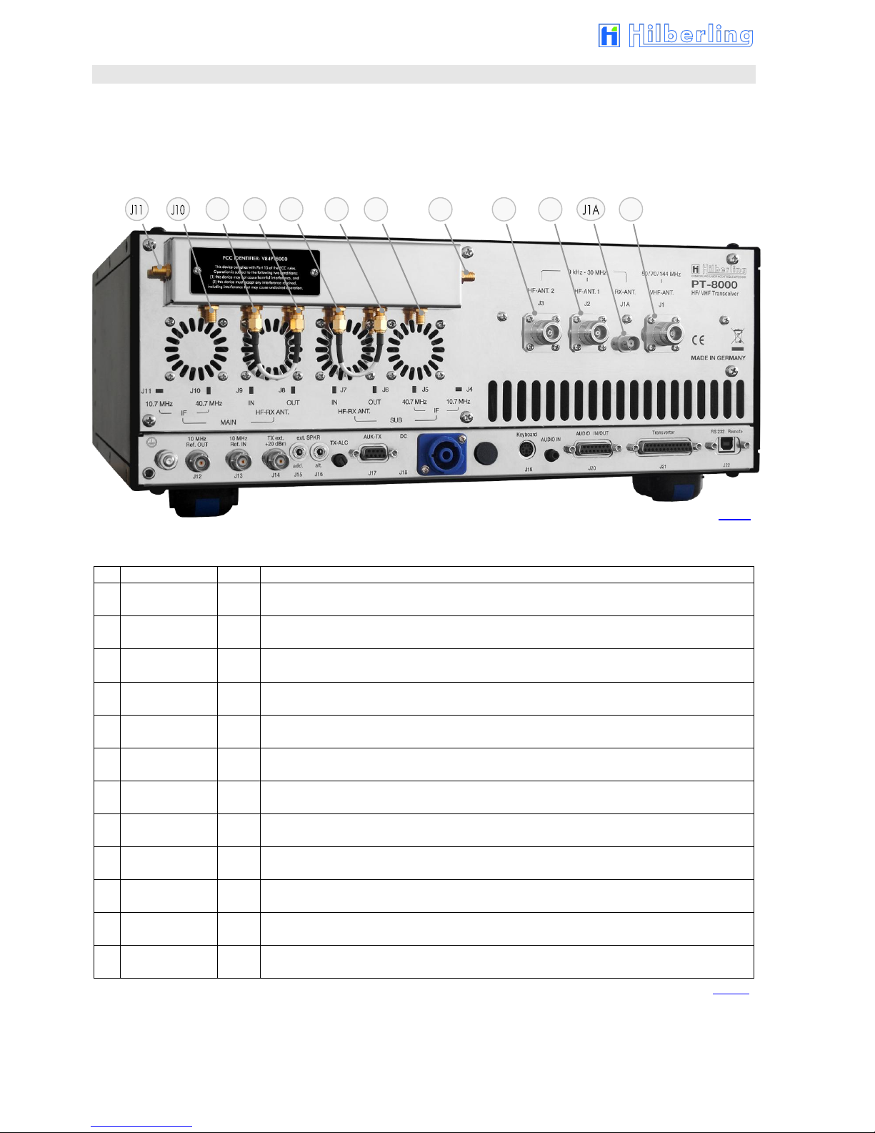
4.1.1 HF/VHF Connectors J1 - J11
No.
Name
Type
Description
J1
VHF-ANT
50/70/144 MHz
N
Input / Output VHF Antenna Range 110 ... 143,990 MHz (RX only)
50 / 70 / 144 MHz Band (RX and TX)
J1A
RX-ANT
9 kHz ... 30 MHz
BNC
Input VLF/LF/MF/HF Antenna Range 9 kHz …30 MHz (RX only)
For DUPLEX mode the input may stay open during transmission.
J2
HF-ANT 1
9 kHz ... 30 MHz
N
Input / Output VLF/LF/MF/HF Antenna Range 9 kHz ... 30 MHz (RX and TX)
J3
HF-ANT 2
9 kHz ... 30 MHz
N
Input / Output VLF/LF/MF/HF Antenna Range 9 kHz ... 30 MHz (RX and TX)
J4
IF 10,7 MHz
SUB
SMA
Output 2nd IF 10.7 MHz of SUB-RX. The output is tapped after the 2nd mixer. No AGC and no 10.7MHz
Xtal filter at that point. Thus bandwidths are determined by prefilters
J5
IF 40,7 MHz
SUB
SMA
Output 1st IF 40.7 MHz of SUB-RX. The output is tapped after the 1st mixer –thus being broadband when
preselector is disengaged
J6
HF-RX ANT SUB
OUT
SMA
HF Antenna Signal for SUB-RX after passing internal antenna switch respectively TX/RX relay. Connected to
J7 (by default) or to input of external equipment (QRM-eliminator, ANT-switch panel etc.)
J7
HF-RX ANT SUB
IN
SMA
HF signal input for SUB-RX. Connected to J6 (by default) or to output of external equipment (QRM-
eliminator, ANT-switch panel etc.)
J8
HF-RX ANT MAIN
OUT
SMA
HF Antenna Signal for MAIN-RX after passing internal antenna switch respectively TX/RX relay. Connected to
J9 (by default) or to input of external equipment (QRM-eliminator, ANT-switch panel etc.)
J9
HF-RX ANT MAIN
IN
SMA
HF signal input for MAIN-RX. Connected to J8 (by default) or to output of external equipment (QRM-
eliminator, ANT-switch panel etc.)
J10
IF 40,7 MHz
MAIN
SMA
Output 1st IF 40.7 MHz of MAIN-RX. The output is tapped after the 1st mixer –thus being broadband when
preselector is disengaged
J11
IF 10,7 MHz
MAIN
SMA
Output 2nd IF 10.7 MHz of MAIN-RX. The output is tapped after the 2nd mixer. No AGC and no 10.7MHz
Xtal filter at that point. Thus bandwidths are determined by prefilters.
Tab. 2
Fig. 2
J1
J2
J3
J5
J4
J9
J8
J6
J7
PT-8000A Operating Manual v2.00.33 5
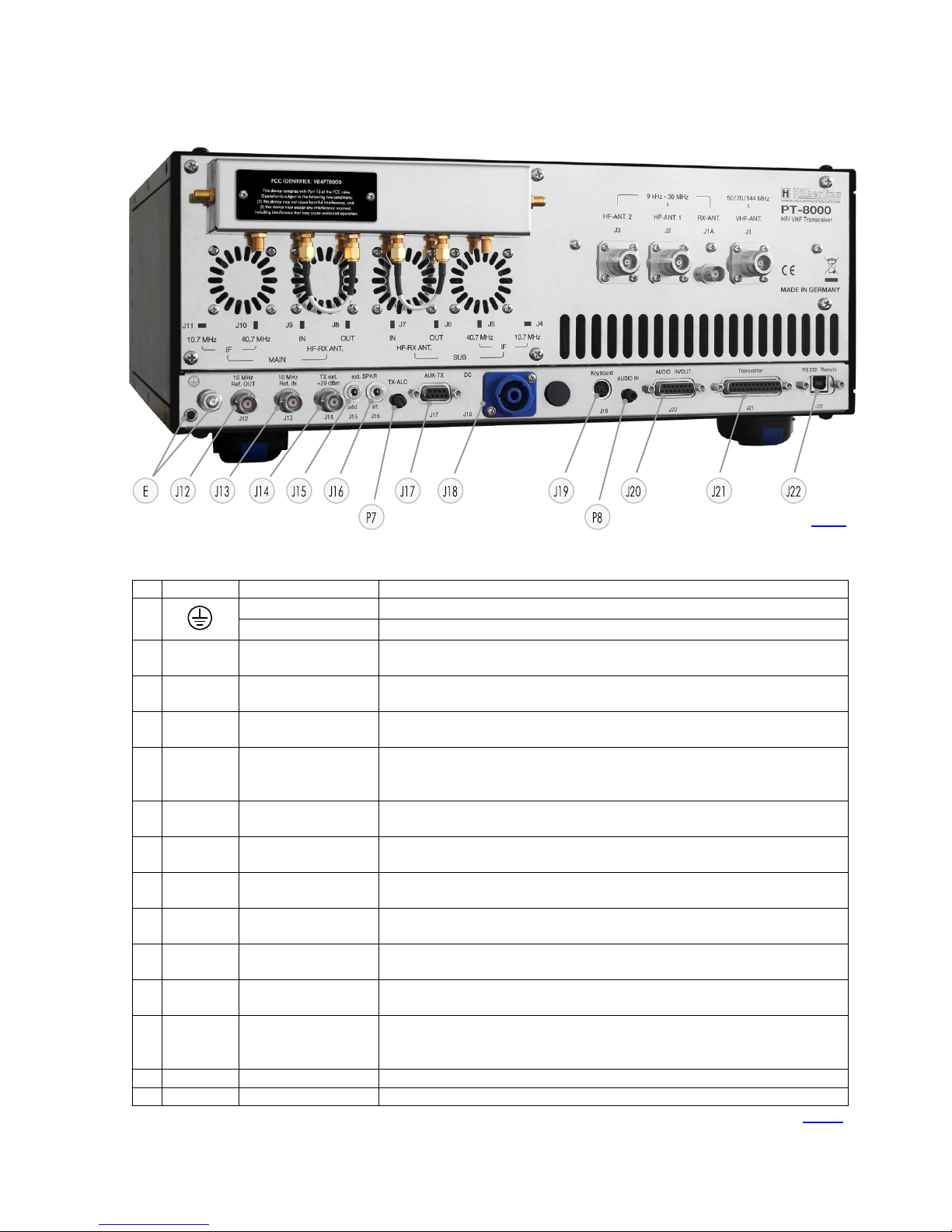
4.1.2 Connection Sockets J12 - J22 and Operating Elements
No
Name
Type
Description
E
Socket 4 mm
Grounding wire (p 10 / Fig. 10) –must be connected toHN-8000 power supply
Threaded Pin M6
Grounding stud –must be connected to station ground
J12
10 MHz Ref.
OUT
BNC
Input for an external 10 MHz reference signal (clock) for synchronization of PT-8000A to other
equipment. The signal delivers +1dBm ±3dB level
J13
10 MHz Ref.
IN
BNC
Output of an external 10 MHz reference clock for synchronization of external equipment to
PT-8000A. Input 10 MHz signal level > -10dBm.
J14
TX ext.
+20 dBm
BNC
TX external output (1.8…148 MHz). Level is +20 dBm to drive transverter or external power
amplifier
J15
ext. SPKR
add.
EIA-453 / IEC 60603-11
TRS 3.5 mm Socket
60 kHz output: Connection to sound card for panorama display/waterfall diagram.
Requirements: Soundcard with 192 kHz sample rate ; Windows®PC ; Hilberling software „PT-
8000A IF-Monitor“, connecting cable
J16
ext. SPKR
alt.
EIA-453 / IEC 60603-11
TRS 3.5 mm Socket
Output audio MAIN- and SUB-RX/ only SUB-RX (Audio Norm/Split); 4.5 W max. @ 8 Ω;
connection external speaker, by default to Power Supply HN-8000 (cable P. 10 / Fig. 11);
J17
AUX-TX
(PTT/ALC)
DE-9
(D-SUB 9-pol)
Auxiliary output/input for TX (wiring see P. 6 / Tab. 4)
J18
DC
IN
CliffCon
4-pol
Power connector for interconnection cable to HN-8000 power supply DC 13.8V / 50V (cable
P. 10 / Fig. 9)
J19
Keyboard
mini-DIN
PS/2 Socket
Access to Main-CPU; further functions TBD
J20
AUDIO
IN/OUT
DA-15
(D-SUB 15-pol)
Various audio signals MAIN/SUB in- and output (wiring see P. 6 / Tab. 4)
J21
Transverter
DB-25
(D-SUB 25-pol)
Connect control cable to transverter (wiring see P. 6 / Tab. 4)
J22
RS232
Remote
USB-B
Input/output data (cable P. 10 / Fig. 12)
1. Connect external equipment to remotely control the PT-8000A (CAT)
2. Interface to update firmware of PT-8000A
P7
TX-ALC
Sensitivity of ALC input (J17, pin 6) from external PA to reduce TX power out (0 ... −10 V)
P8
AUDIO IN
Sensitivity of Audio data input (J20, pin 2) –rated 0 dBm @ 50 Ω
Tab. 3
Fig. 3

6
4.1.3 Wiring of J15 - J21
No
Name
Type
Function And Outline
J15
ext. SPKR
add.
1Tip 60 kHz OUT MAIN RX
2Ring 60 kHz OUT SUB RX
3Sleeve GND
Caution: Using mono type plugs will shorten the
audio output and may damage the
transceiver
J16
ext. SPKR
alt.
STATUS: Audio NORM Audio SPLIT
1Tip AUDIO OUT MAIN and SUB RX SUB RX
2Ring <not connected>
3Sleeve GND GND
Caution: Using mono type plugs will shorten the
audio output and may damage the
transceiver
J17
AUX-TX
(PTT/ALC)
1PTT to HF-PA 6EXT ALC IN (0 ... −10 V **)
2PTT EXT IN 7PTT to HF-PA
3PO FORWARD DC OUT 8PO REFLECTED DC OUT
4PTT to VHF-PA *9EXT TUN/PA READY=LOW
5GND
* Circuit to ground ** adjustable by P7
J18
DC
IN
2−13.8 V DC (RX ; switched by relay)
1+ 50 V DC (PA ; switched by relay)
1−GND
2+ 13.8 V DC (Relay HN ; switched to GND by
PT8000 switch POWER
J19
Keyboard
1DATA
2<not connected>
3GND
4VCC
5CLK
6< not connected >
J20
AUDIO
IN/OUT
1PTT AUDIO A 9PTT AUDIO B
2AUDIO DATA IN 10 AUDIO DATA GND
3AUDIO DATA GND 11 AUDIO DATA OUT
4GND 12 GND
5AUDIO OUT MAIN-RX 13 GND
6GND 14 AUDIO OUT SUB-RX
7GND 15 TP1
8TP2
J21
Transverter
1GND 14 AGC VOLTAGE MAIN
2AGC VOLTAGE SUB 15 DATA EXT PA A
3DATA EXT PA B 16 DATA EXT PA C
4DATA EXT PA D 17 GND
5+12V Transverter 1 *** 18 PTT Transverter 1 A
6PTT Transverter 1 B 19 GND
7+12V Transverter 2 *** 20 PTT Transverter 2 A
8PTT Transverter 2 B 21 GND
9< not connected > 22 < not connected >
10 DC EXT PA CONTROL 23 GND
11 GND 24 Debug TX
12 Debug RX 25 GND
13 GND *** max. 1 Ampere
Tab. 4
Connector for
Panorama Display /
Waterfall Diagram

PT-8000A Operating Manual v2.00.33 7
4.2 Connectors at Front Panel
4.2.1 Connection Sockets 1 - 3
No.
Name
Type
Description
1
MIC-PTT
Microphone Threaded Socket
8-pol
Microphone connector for Hilberling T9 and Data input 0 dBm
2
PHONE
EIA-453 / IEC 60603-11
TRS 6.3 mm Socket
Headphones (impedance 8 ... 600 Ohm)
3
CW-KEY
EIA-453 / IEC 60603-11
TRS 6.3 mm Socket
Connector: –Keyer for CW (morse key/ keyer with Paddle / automatic keyer)
–Control of internal CW Keyer
Tab. 5
4.2.2 Wiring
No.
Name
Figure
Function And Outline
1
MIC-PTT
0 dBm
1MIC AUDIO IN
2PTT
3MAIN-RX AUDIO OUT (e.g. headset)
40 dBm IN
5MIC AUDIO IN / DC +10 V internal
6SUB- RX AUDIO (e.g. headset)
7MIC GND
8PTT GND
2
PHONE
1Tip + Audio OUT MAIN
2Ring + Audio OUT SUB
3Sleeve GND
NOTE: Audio for PHONE is derived from audio preamplifier
especially designed for phone operations.
Caution: Using mono type plugs will shorten the
audio output and may damage the
transceiver
3
CW-KEY
STATUS: Int. Keyer * Ext. Keyer **
1Tip DOT CW-Key
2Ring DASH <not connected>
3Sleeve GND GND
* using the internal keyer (iambic or normal) (s. P. 64)
** using an external keyer (s. P. 64)
Tab. 6
1
2
3
Fig. 4
Electret Mic
Dynamic Mic

8
5 POWER SUPPLY HN-8000
5.1 General Description
Each PT-8000A is equipped with its power supply HN-8000, which delivers 13.8 V DC @ 8 Amps internal
/ 5 Amps. external and additional 50 V DC @ 14 Amp. max., i.e. the overall performance is about 900
W.
Operating voltages from the mains can be in the range of 90 VAC to 260 VAC without any degradation in
output power. Only the efficiency will vary slightly. It complies with special regulations in some countries
regarding power factor compensation (PFC). The HN-8000 provides triple HF shielding and feedthrough
filters.
In addition the HN-8000 provides an auxiliary output 13.8 VDC @ 5 Amp at the back panel, e.g. to
deliver further shack equipment.
5.2 Connectors at Rear Panel
Connection Sockets J1 - J4
No
Name
Type
Description
J1
AC
IEC-60320-C13 male connector
Input main power 90 –260 V AC 50/60 Hz (cable P. 10 / Fig. 8);
J2
AUX
13.8 VDC
2x Socket 4 mm;
+ Clamp
Auxiliary output 13.8 V DC / 5 Amp.
E
Socket 4 mm
Grounding wire –must be connected to PT-8000A transceiver (cable P.10 / Fig. 10)
Threaded Pin M6
Grounding stud –must be connected to PT-8000A transceiver and to station ground
J3
SPKR 8 Ω
EIA-453 / IEC 60603-11
TRS 3.5 mm Socket
Input audio signal MAIN- and SUB-RX/ only SUB-RX (Audio Norm/Split) from PT-
8000A socket J16 to built-in speaker; 4.5 W max. @ 8 Ω; (cable P. 10 / Fig. 11)
J4
DC
Cliffcon Socket
4-pol
Power connector for interconnection cable to PT-8000A (cable P. 10 / Fig. 9; PT-
8000A Socket J18)
AC-FUSE
Circuit breaker for AC mains at rear panel socket J1 rated 16 Amp @ 90 –260 V AC
Tab. 7
E
J3
J4
J1
J2
Circuit breaker for AC/J1
Fig. 5

PT-8000A Operating Manual v2.00.33 9
Make sure before connecting to mains to turn OFF (press down) both
switches (LINE and PA).
5.3 Operating and Display Elements at Front Panel
6 ACCESSORIES
6.1 Base Station Microphone Dynamic T9
Best suited for all voice operations is the Hilberling Dynamic T9 especially
designed for the PT-8000A.
Isolated from any mechanical vibrations and designed to be used from more
closer as well as from greater distance it will always guarantee high fidelity
audio and if desired an extra punch to the signal.
It is equipped with a microphone preamp.
Impedance is 600 Ω@ 1 kHz. The acoustic characteristic is kidney-shaped.
Finish: Black anodized
6.2 Wiring / Cables
AC line voltage cable (power grid ⬄HN-8000) length approx. 1.7 m
ON/OFF for DC Low Power
13.8 V (J4) PT-8000A RX and
DC AUX 13.8 V (J2) rear panel
ON/Off for DC Output
50 V (J4) PT-8000A
TX-Power Amplifier
Automatic Fuse for DC-
Output 13.8 V / 5 A (J2)
AUX rear panel
Power Meter
PA DC-Input
Fig. 6
Fig. 7
Fig. 8
The power meter indicates the
DC input power of the final
power amplifier –hence
computation of efficiency could
be easily done by comparing
RF-power out as indicated on
PT-8000 display and DC-input
shown here.

10
DC power cable (HN-8000 ⬄PT-8000A) length approx. 1.2 m
Ground cable (HN-8000 ⬄PT-8000A) length approx. 1.0 m
Speaker cable (HN-8000 ⬄PT-8000A) length approx. 0.9 m
Data cable (PT-8000A / USB-B ⬄PC / USB-A) length approx. 1.8 m
6.3 Operating Manual and Software/Documention CD
This manual version 2.00.xx
CD
Fig. 9
Fig. 10
Fig. 11
Fig. 12
Fig. 13a
Fig. 13b

PT-8000A Operating Manual v2.00.33 11
7 INSTALLATION /INITIAL OPERATION
7.1 Introduction
Prior to any operation of the PT-8000A read this Operation Manual carefully
notably before activating the transmitter.
The PT-8000A will be delivered with the following presettings:
The preselectors of both RX are aligned and all data are stored in RX-
CPU memory which is buffered through a NiCd battery.
The transmitter is unlocked according to the band plans of that IARU
region (see Page 36) the PT-8000A is delivered.
The IARU region can be changed by software update.
Prior applying main power to the power supply HN-8000 please verify the
following points (7.2).
7.2 Cable Connectors
Please check at the rear panel of PT-8000A and HN-8000:
Antenna(s) is/are connected properly
Grounding stud is connected to station ground
Grounding wire is connected to both PT-8000A and HN-8000
DC cable is connected to both PT-8000A and HN-8000
For initial operation we recommend not to connect external amplifier,
transverter or devices for remote operation.
7.3 Initial Settings
Please check at the front panel of HN-8000 (see Page 9):
Both switches (LINE und PA) are pushed down (off)
Please check at the front panel of PT-8000A (see Page 12):
Main switch (POWER) is pushed down (off)
Volume controls MAIN and SUB are set fully counter clockwise
TX-PWR knob is set fully counter clockwise
MIC-GAIN knob is set fully counter clockwise
PROC knob is set fully counter clockwise
Microphone T9 is connected
Connect power supply HN-8000 to main power
Turn on both LINE and PA on HN-8000
Turn on POWER at PT-8000A
It is up to the operator to switch PA off (switch PA at the HN-8000) during
reception only.
Power On

12
8 OPERATING AND DISPLAY ELEMENTS
In this chapter the operating and display elements will be introduced.
8.1 Main Operating and Display Elements
Function
Name
Description
Power ONOFF
POWER
All supply voltages from power supply HN-8000 are disconnected by this switch
Before turning ON verify settings for MIC-GAIN, PROC, TX-PWR and audio
volume settings for MAIN and SUB-RX are turned fully counter-clockwise.
After switching ON:
LED MAIN-RX will illuminate
LEDs of all pushbuttons will illuminate for 1 second (functional check)
Volume MAIN-RX
(PT + HN / PT only)
ONOFF Speaker
(PT only)
MAIN
Volume for audio MAIN-Receiver.
The RX is always turned on –audio is always present regardless of RX-status (active or in the
background –see below).
Pushing toggles the speaker of PT-8000A ON and OFF (s. P. 53).
Volume SUB-RX
(PT + HN / HN only)
ONOFF Speaker
(HN only)
SUB
Volume for audio SUB-Receiver.
The RX is always turned on –audio is always present regardless of RX-status (active or in the
background –see below).
Pushing toggles the speaker of HN-8000 ON and OFF (s. P. 53).
TFT-Display
÷
The display represents the primary means to control through soft switches (“Softkeys”) and to show
all relevant data for RX and TX operations.
Primary VFO Tuning Knob
active RX
÷
Tuning of VFO A/B of active RX. MAIN- and SUB-RX are always receiving. The term active is used in
the following context: Active means which RX (MAIN or SUB) is controlled by the main Display
(through soft switches) and which RX-Data is completely shown in the display.
Default setting: MAIN RX is the active RX.
Secondary VFO Tuning
Knob background RX
SUB VFO
Tuning of VFO A/B of RX, which is not the active one i.e. working in the Background (see above).
Default setting: SUB-RX is in the background
Set internal Reference
REF-SET
When operating the PT-8000A with its internal reference (10MHz-VCXO) this control will allow
calibration the VCXO. Tuning range ± 1 ppm (s. P. 54). The LED EXT-REF will illuminate if an
external reference signal is detected
Tab. 8
POWER
ONOFF
TFT Display
(s. P. 13)
Volume MAIN- and SUB-RX
Speaker ON⬄OFF
VFO (MAIN) Tuning
„active“ RX (s. P. 38)
VFO (SUB) Tuning
RX „in the background“
MAIN-RX / TX / SUB-RX
LED for status (s. P. 19)
Softkeys
(s. P. 13)
Fig. 14
Softkey menu
(s. P. 13)
MIC-GAIN
(s. P. 68)
PROC
(s. P. 68)
TX-PWR
(s. P. 69)
Table of contents
Other Hilberling Transceiver manuals


