Foreword
- Please read this manual carefully before you use this product and retain it properly
for future reference.
Features
Brief Introduction
02
02
03
04
05
09
13
15
18
05
07
09
11
Contents
About this manual
Packing list
Brief introduction
Specification
Wireless HD Transmitter:7051
Wireless HD Receiver:3051
Wireless HD Transmitter:7051
Wireless HD Receiver:3051
Trouble shooting
Mechanical information
- CVW reserves the authority to modify the instruction manuals.
- If there is any question or difficulty about the operation of product, please feel free
to contact us or the dealer.
As the widely use of live broadcasting , many problems about wiring appear, such as
the high cost and short life time of the cable. Further, some other factors affect the
user experience of live broadcast, such as the insufficient cable protection and the
tread bycrowded people, which will lead to the poor cable transmission capability or
even to accident. PRO200 provides you more convenient and safer solution for live
broadcasting. With the advantage of long distance transmission, plug-and-play usage,
it can satisfy your various indoor and out door shooting requirements. With addition of
its free cable wiring needed,it will bring much safer and more professional experience
to you!
02
Features
The product with its transmission distance of up to 200 meters can meet the demands
of film shooting, television broadcasting, live events, large conference, etc.
The product delivers uncompressed real-time 1080P/60Hz full HD video (4:2:2, 10bit).
Support HDMI, HD-SDI, 3G-SDI.
Full hardware design, plug & play;
Support manual setting for channel switching and broadcast mode.
Support SDI time code transmission (time code format: ATC_VITC, ATC_LTC).
Support SDI camera recording trigger function (Start/Stop Flag) transmission.
Comply with EDID Structure 1.1 and support HDMI 1.3.
Support AES128/256 bit image encryption.
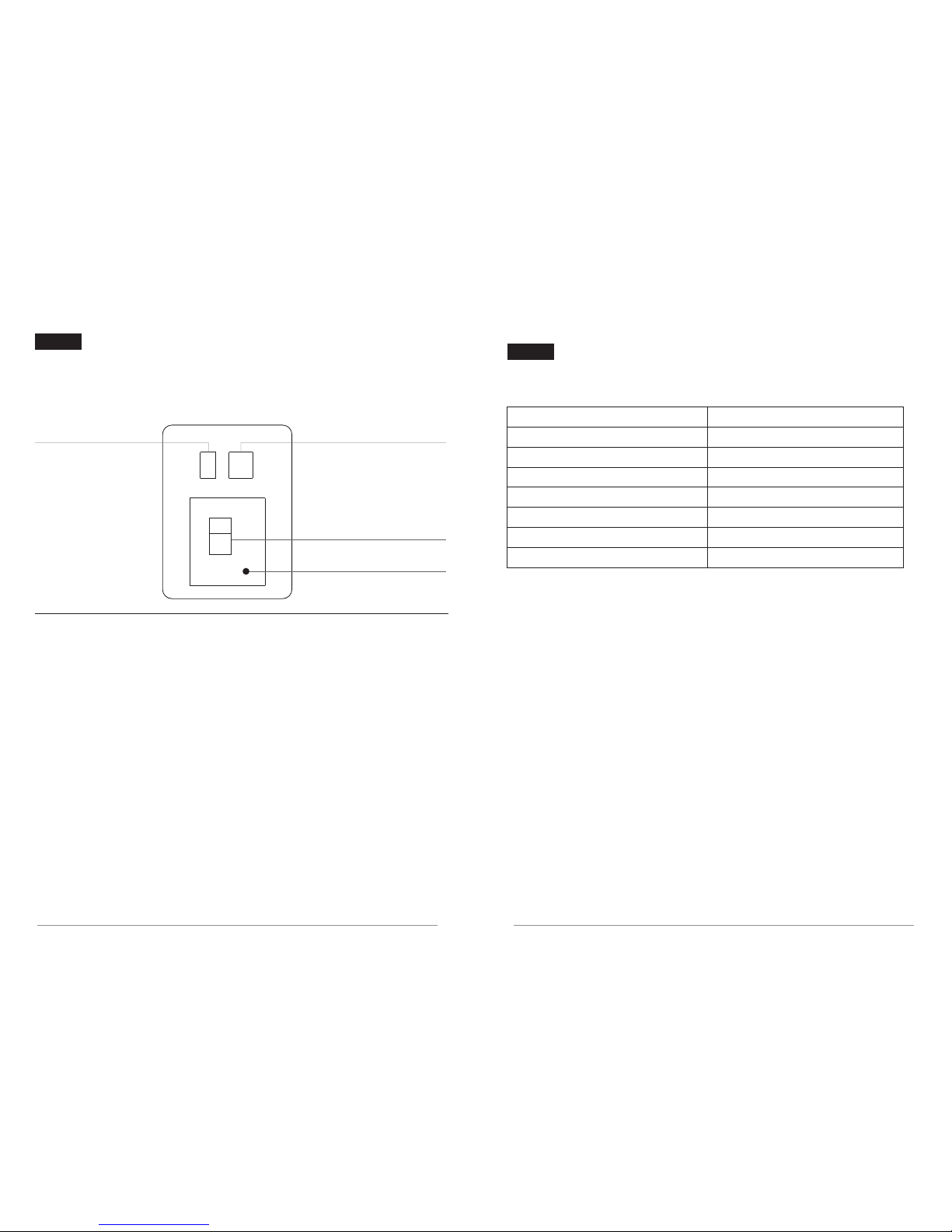
LED Digits Display description
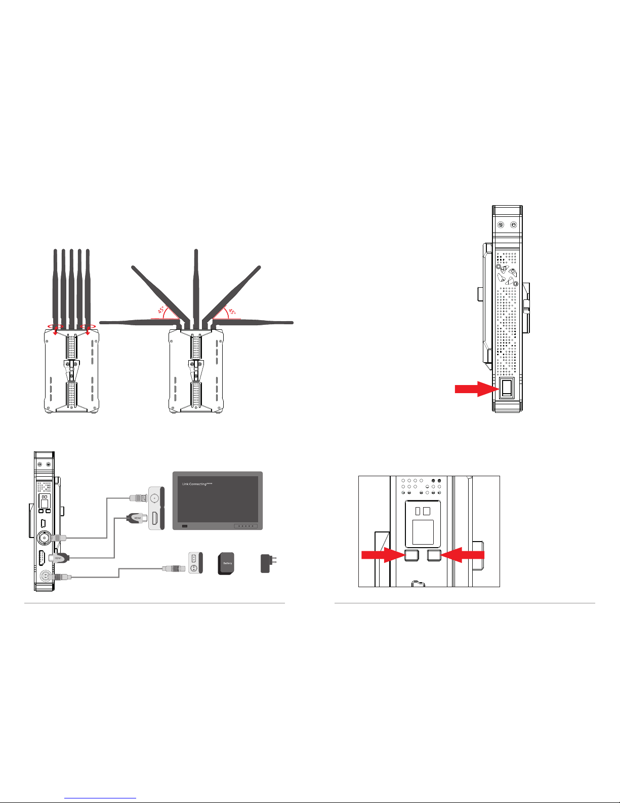
Product Installation
Transmission Distance Description